
Leaderboard


Popular Content
Showing content with the highest reputation on 14/11/20 in all areas
-
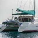
I have no interest in these except being a satsified buyer These lifejackets are around £270-£300 new, and this chappie is selling them for £40 inc 48hr delivery. Vaccum packed and unopened. I have had some from him in previous years and they are excellent lifejackets. (ordered another one from this batch) Designed for 'offshore' use for people in heavy Winter clothing they have almost twice the buoyancy of 'standard lifejackets' and exceed the MCA requirements for 'turning you face up' Have a chin support to keep your mouth out of the water (and a hood to stop waves going in your mouth or up your nose) Have crutch straps so they don't slip over your head. Twin chambers each having enough buoyancy to keep you afloat. The offshore industry 'cycles' its stock even before the expiry dates - they have 2 years left (typically 4/23) before they are due for commercial re-certification, and will last for years in leisure use. It is probably cheaper to keep them for 3 years and get some from a future batch than it is to have a lifejacket serviced. Ideal for wearing when 'Winter locking' on icy surfaces. I'd recommend them even for 'muddy ditch' usage. https://www.findafishingboat.com/lifejackets-crewsaver-275n-twin-chamber-new-unused/ad-114225 https://www.crew-safe.co.uk/acatalog/Crewsaver-Seacrewsader-SOLAS-275N-Twin-Chamber-Lifejacket.html The Seacrewsader 275N Twin is designed to SOLAS 2010 regulations, and outperforms the new requirements to provide increased performance in the most demanding environments. Improved body angle, mouth freeboard and face plane angles make the Seacrewsader even safer at sea. Together with the improved rotating times each chamber is fitted with two 60 g CO2 cylinders, activated by UML MK5i standard automatic inflation mechanisms* - and a 3.5 psi relief valve to ensure full buoyancy during single or double chamber inflation. The Seacrewsader 275N Twin is designed for extreme working environments and is also suitable for abandonment purposes. The high buoyancy level provides added protection when heavy work gear and clothing is worn. The new, more compact cover is a robust fabric to withstand the most arduous conditions without damage to the lifejacket and internal bladders. Crotch straps come fitted as standard.4 points
-
This post cannot be displayed because it is in a forum which requires at least 10 posts to view.
-
This post cannot be displayed because it is in a forum which requires at least 10 posts to view.
-
This post cannot be displayed because it is in a forum which requires at least 10 posts to view.
-
This post cannot be displayed because it is in a forum which requires at least 10 posts to view.
-
This post cannot be displayed because it is in a forum which requires at least 10 posts to view.
-
This post cannot be displayed because it is in a forum which requires at least 10 posts to view.
-
I'd say the coal vs wood thing is a red herring. Somehow, somewhere combusted gases are escaping your stove into the cabin. If this was my stove I would stop using it IMMEDIATELY. CO is extremely dangerous and I can tell a story about a relative semi paralysed by it dragging his unconscious family outside (they fortunately survived) if that will encourage you. Once I had stopped using ANY fuel in the stove the next thing I'd do is work out where the leaks are emanating. I keep smoke bombs for this purpose (available from chandleries). Any one of the rope seals could be the issue - the fact that smoke escapes the door suggests that that's the problem - I'd have replaced these on the strength of your newspaper test! Depending on the stove there might be seals in the actual body of the stove. It is expensive but necessary to recondition your stove and replace all of these seals eventually. I personally would blank off the mushroom vent that is near the chimney. Another possibly cheap/easy fix to improve the draw and get the exhaust further from the cabin is a longer chimney. I'm not as experienced as the other posters who have replied and perhaps I'm more paranoid than they are, but I would not mess about with a stove. Test for leaks, replace all the ropes, block off any ventilation near the chimney, use a longer chimney, and yes clean the flue out regularly.3 points
-
This post cannot be displayed because it is in a forum which requires at least 10 posts to view.
-
This post cannot be displayed because it is in a forum which requires at least 10 posts to view.
-
So your few months of living on the cut makes you an expert to add to your vast list of professions? You condemn those living in a "cheapo" marina as having a "bad track record" Your attitude madam is some of the very worst kind of prejudiced and hypocritical I have ever come across!2 points
-
This post cannot be displayed because it is in a forum which requires at least 10 posts to view.
-
This post cannot be displayed because it is in a forum which requires at least 10 posts to view.
-
This post cannot be displayed because it is in a forum which requires at least 10 posts to view.
-
I dont know what the processor on my rasp pi is doing any of the time.?2 points
-
I met one of the trip boats out of Birmingham (something 4 awhile) in a tunnel with two big lights on it, as we got closer he turned them both off, I wondered where he had gone to.2 points
-
Finally got around to sitting in front of my computer and writing some code for the home made BMS which I’ve attached to the CALB cells. Well, just one set of cells ie 200Ah which is plenty for the moment. Firstly, pleased to see that the voltages of the 4 cells are within 2mV of each other as supplied from China. Secondly, wow the internal resistance is so low! Adding my power supply to charge at 5A (which ok is not much in the context of 200Ah) only increases the cell voltage by about 3mV. Amazing! I will have to be careful to ensure clean contacts etc for the interconnects, otherwise there is a good chance that the interconnect resistance will be more than the cell resistance! And also wrote the code to operate the Tyco BDS-A battery disconnect relay, which as we know needs a pulse of around 75mS to operate. It takes about 3A and having a longer pulse or worse, somehow leaving the 12v applied, will no doubt melt the coil in short order. So it’s important to have a robust pulse generator. I know that MP created some dedicated hardware for it but for me it was just 7 lines of code. And 4 of them were to turn off low and high priority interrupts (to ensure the processor wasn’t distracted doing something else) and turn them on again afterwards. Then just 3 lines of code, 1) turn on the MOSFET, 2) wait 75 mS, 3) turn off the MOSFET. Easy Peasy! Does demonstrate the advantages of using relatively low tech like a PIC or Arduino whereby being in total control of the processor, vs say a Raspberry Pi with a huge linux operating system whereby you don’t really know what the processor is doing half the time.2 points
-
This post cannot be displayed because it is in a forum which requires at least 10 posts to view.
-
This post cannot be displayed because it is in a forum which requires at least 10 posts to view.
-
Confusion with the boat's chimney?2 points
-
This post cannot be displayed because it is in a forum which requires at least 10 posts to view.
-
This post cannot be displayed because it is in a forum which requires at least 10 posts to view.
-
This post cannot be displayed because it is in a forum which requires at least 10 posts to view.
-
Just found this thread, and joined canalworld! I worked on the Soar job at its inception, and continued for most of the long hot summer. The biggest problem was the mechanical unloading... Despite having an absolutely superb 360 driver, (Alan???), the shuts were in a terrible state pretty quickly. This led to gravel getting packed solidly into the bilges, and on more than one occasion, a sharp corner puncturing the hull. A time of my life I wouldn't have missed for anything, despite the relentless work and less than ideal conditions. "Shirley" was steered by a wonderful bloke called Ralph (Mould/Moulds???), who had worked pairs for a fair proportion of his life, and who lived on a houseboat down the backwater at Thurmaston Lock. "Whitby" was steered by a hilarious character, Barry from Brum, who's humour and friendship were much appreciated. I often stop in the area if delivering nearby, and walk down Mill Lane for a reminiscing session on the lock bridge. Ive got a painting somewhere of WYE in Thurmaston lock, which John West did for me a couple of years later... I'll post it if I dig it out with the xmas deccies!2 points
-
This ^^^^ tells me that it's been neglected badly, because if the owner can't be bothered to do the blindingly obvious when they're trying to sell the thing, or maybe hasn't the knowledge or skills to do so, you can't possibly believe it's been otherwise well maintained. Find yourself a boat someone has loved and cared for.2 points
-
Thank you the crowdfunding page is heading around wrg via facebook.1 point
-
This post cannot be displayed because it is in a forum which requires at least 10 posts to view.
-
This post cannot be displayed because it is in a forum which requires at least 10 posts to view.
-
This post cannot be displayed because it is in a forum which requires at least 10 posts to view.
-
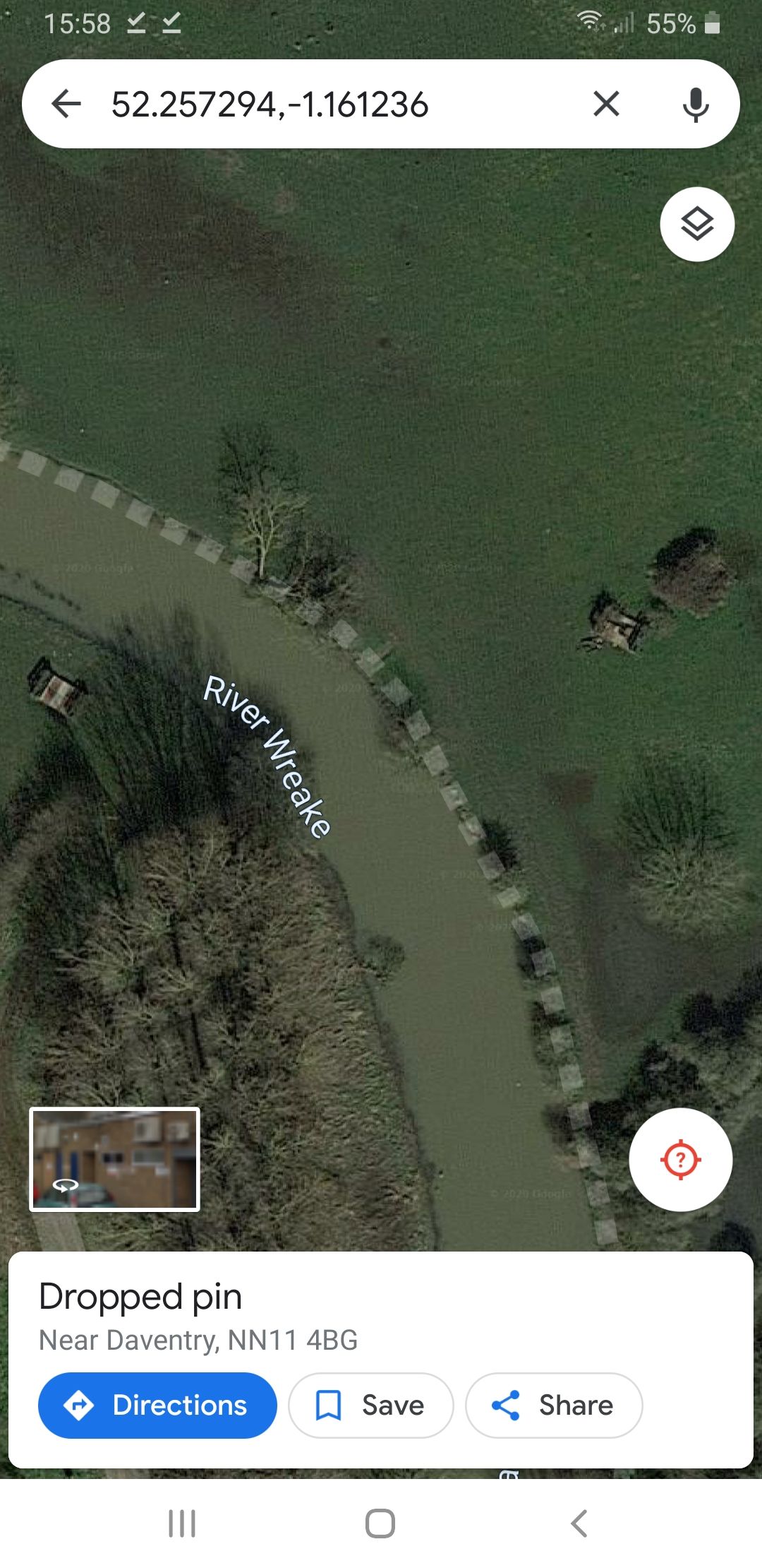
There has been a temporary steel bridge structure in fields either side of the canal for years a bit further north.....now very overgrown.
 1 point
 -
We had one on a 30 foot NB, very efficient and from memory no problems with condensation (probably due to the excessive 'ventilation' around the doors') Passed a number of BSS examinations as still compliant under 'grandfather rights'. Sold it and it went down to London (Brentford) as a Liveaboard.1 point
-
I owned an old Harborough with a couple of those fitted 25 or so years ago, they were old even then. Worked well but caused much condensationstuff.1 point
-
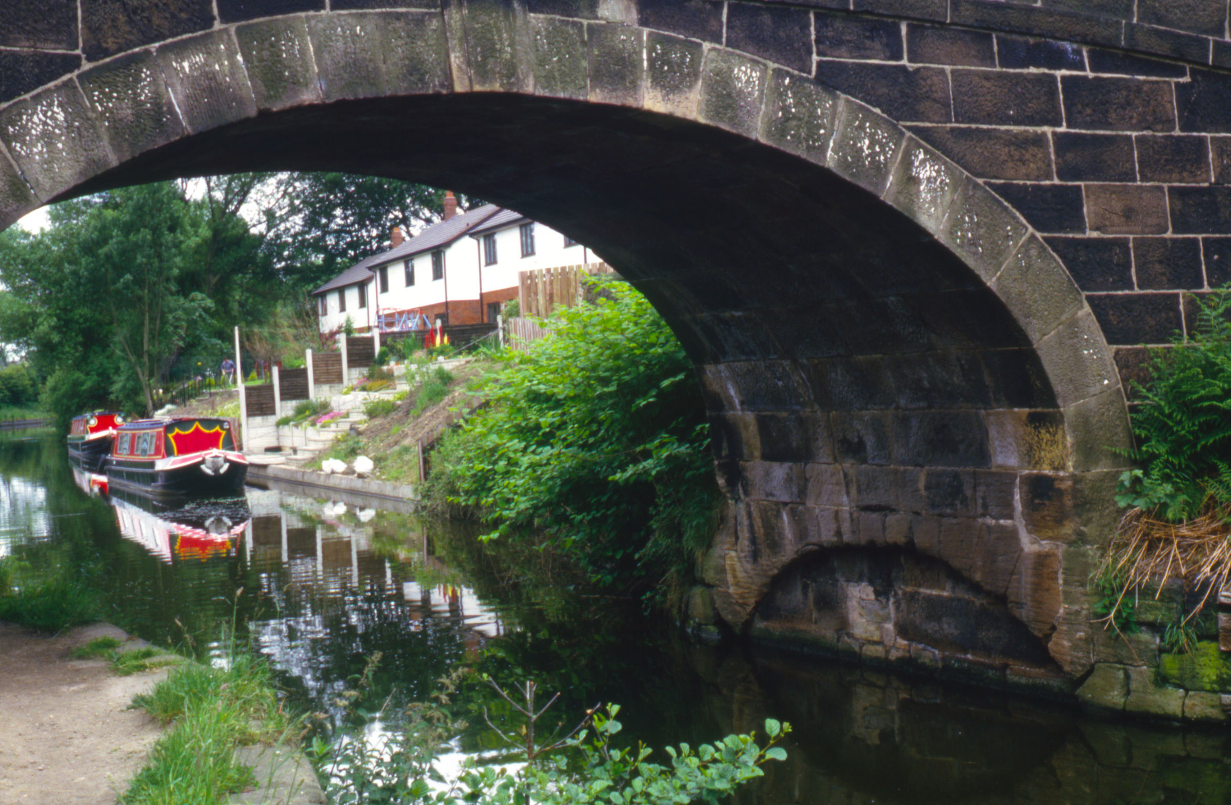
There are a range of types; Brindley and Rennie liked those which lay flat on the canal bed, though raised slightly to allow them to operate, automatically in theory, when there was a flow of water. They soon became covered in rubbish and silt. Whitworth used more conventional emergency gates on the L&LC, but without a balance beam. When there was a significant flow, they could be swiftly push out to stop further water loss. There are probably other types, The photo shows one of Rennie's design on the Lancaster at Adlington. It had two gates which folded onto the canal bed, so could operate in either direction. There was a fixed wooden vertical in the centre of the semicircular arch, and either gate would seal against it.
1 point
-
Definitely Mould. Myself and my partner at the time spent hours with him and his lovely Wife. Just sitting on the bank of the backwater and discussing literallty, life, the Universe and everything! Great times1 point
-
2 to 3 kW is the power required, depending on the hull, water depth and so on. No consumption when you are in a lock, unlike a diesel engine. Multiply that by the number of hours you cruise for the kWhrs you'll need from the battery. <pedant> Watt is a unit of power, not energy, so watts per hour isn't meaningful</pedant>1 point
-
This post cannot be displayed because it is in a forum which requires at least 10 posts to view.
-
This post cannot be displayed because it is in a forum which requires at least 10 posts to view.
-
It is not just the cruising, it is 'everything else' if you have an electric boat. It will also depend on the weather, the amount of solar you have, how far you you mean by 'cruise for a week' ( 1 hour per day, 12 hours per day, 168 hours per week) You ask an impossible question.1 point
-
Microwaves are for heating up baked beans. Once you advance your cookery skills to be able to heat them in a pan, you have no need for one in a boat - and your alternator/batteries will breath a sigh of relief!1 point
-
Are you aware of how much 'leccy a microwave uses? The 'wattage rating' of a microwave is the amount of power going into the food, not the amount it uses. A microwave will typically use 2x its rated output, so an 850w microwave would actually draw 170amps from you battery. If it takes 10 minutes to defrost and reheat you frozen 'stew' then you would (probably) need to run the engine / alternator for 25-30 minutes to replace it, Managing electricity will be the hardest thing you need to learn, and having an 'electric' boat is even more difficult.1 point
-
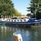
It's moored next to Magenta.1 point
-
This one justifies a visit and if it appeals, a full survey, with the potential purchaser in attendance and ready to put down the cash on the day. If the hull is sound, then get all the other liveaboard necessities sorted. To me this means: Two means of heating Plenty of solar Plenty of good batteries. One or two good invertors A boat which has good electrics A boat which has a BSC. Decent water capacity. No rust, no water ingress. Evidence of ownership Bill of Sale, plus some recent receipts, otherwise it could be stolen or be owned by someone else, or subject to a debt.1 point
-
" Being a few inches wider than than the standard narrowboat makes a noticeable difference" This in the advert for the Springer, is a worry, if the boat is over 6'11" wide there will be the possibility of problems on narrow canals. The route discribed is all wide locks, where this would not show up. All told there are difficulties with this boat. Bod1 point
-
On this day in 2005 Southern Oxford below Napton by br 1111 point
-
Thanks for this and yes what you said is pretty much what was in my mind. A route to Staines following the Colne Brook was the only feasible one that I could imagine but is quite a long way and would still involve some major engineering works. Keith1 point
-
Gordon Bennett ....... another one! "If I start my advert off with a question, then suggest my own views followed by a request for help from them. Nobody will suspect my link leads to my website where they fill out their details!!!!1 point
-
precise? not quite - that's only an approximation to thirteen significant figures. as teacher would have said : "needs to try harder". coat ..................................1 point
-
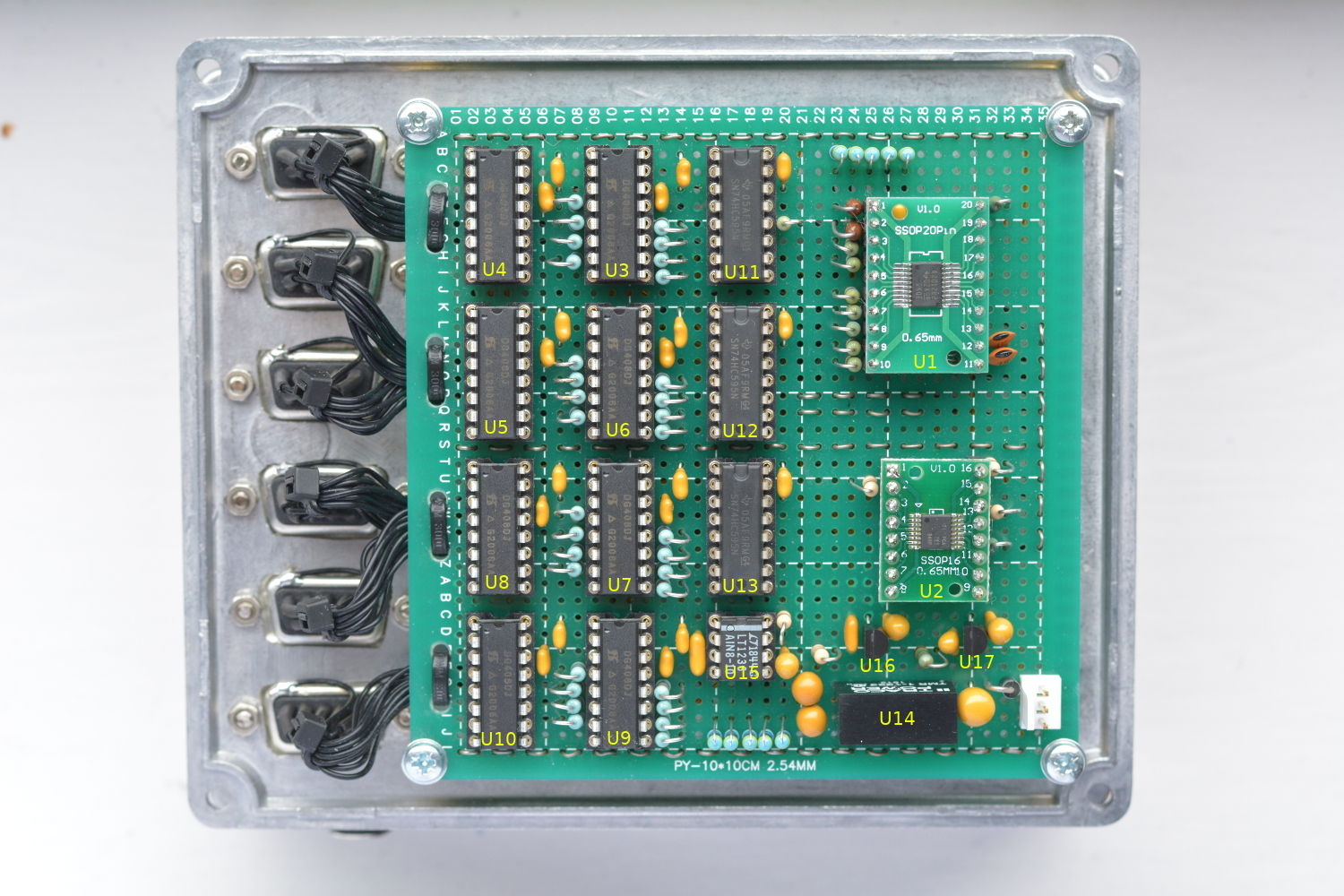
The past couple of months have been fairly heavy going with this project - a final push to get a BMS designed, built and installed. We're beginning to see light at the end of the tunnel. The MK2 prototype is now installed although more work is needed to move the current the measurement functionality across to the new system. Just a quick re-cap on this project so far: 12 CALB 210Ah batteries purchased from EV Support in 2017, and installed with no BMS. The only means of monitoring for the first year was via a 5 digit panel volt meter, and 3 ammeters. A under/over voltage cut off switch was implemented using a BlueSea Systems remote controlled switch wired to two off-the-shelf voltage switch modules. In 2018, a rudimentary means of estimating state of charge was lashed together using a raspbery pi zero and a waveshare ADS1256 module. A few op-amps in a breadboard provide some level shifting and scaling for the ADC. Two years later, this lash-up is still running in on a breadboard on the top shelf of the electrical cupboard. The means of logging data via a google sheet, and plotting using the graphing facility has proved to exceed our expectations regarding reliability and flexibility. It's extremely useful to be able to view the live graphs from anywhere using the google sheets app and it has the ability to share access with family members etc... Time eventually came to build a MK2 unit to overcome some of the limitations, and make a proper installation. Also by this point, I was beginning to get a little nervous about what might be going on with the individual cell voltages. We have only ever carried out spot checks on the cell voltages, but there's never a convenient time to do it. Looking at my spreadsheet, the last measurements were taken nearly a year ago! By this point I have a reasonable idea of what was needed, and what I wanted! I was hoping that an off-the-shelf system would be available by now, as what we're doing isn't exactly novel, and we're not alone in needing a means of precisely measuring multiple voltages. Each time i've looked, the available systems haven't satisfied our specific needs. For instance, many of the multi-cell monitoring solutions are designed for long strings of cells in series, not series-parallel combinations. Also i'm not convinced by the accuracy if the individual per-cell PCB modules as the ones i've seen just rely on the built-in reference within the microcontroller. Having become accustomed to seeing the overall pack voltage displayed with mV resolution and how useful this is whilst observing charge/discharge, I was determined to design something at least as good, but also had an accuracy to complement this resolution. i.e. able to measure the 12V pack voltage within few millivolts. Our setup adds extra complication in that we have 12 cells to monitor. Whilst we could add connecting links between the cells to reduce the number of voltages which need to be monitored, we've chosen not to add the links for the following reasons; Firstly it would be a bit awkward due to the physical layout. Second I believe it might reduce the fault resilience of the pack i.e. 1 faulty cell might then take out 2 more cells. Finally it would not be easy to measure the individual performance of the cells without breaking the links. The system I've ended up designing, for the most part follows a very traditional layout of ADC, instrumentation amplifier and multiplexer. It provides 30 measurement nodes with a somewhat unusual, but flexible multiplexing scheme. It is possible to measure differential voltages between any two nodes; therefore only 5 nodes are needed per battery pack. This scheme enables the polarity of the measurement to be taken in forward and reversed directions. By subtracting the reversed measurements it is possible to eliminate voltage offset of the signal path. A precision voltage reference IC is available via internal nodes 31 and 32 to allow the system to continually self-calibrate. The C code for the raspberry pi is now fully written, I've ended up reusing most of my old python script for uploading the data samples to google sheets. The next phase is to produce some meaningful graphs/dials on the google sheet using the data. I've ended up doing a fair bit of verification work on this prototype unit, even checked it against a reference standard. At 10V the measurement error against the standard was less than 1.5mV. This equates to an error of 0.015%, which is acceptable and well within the spec of the reference IC. It's possible to further reduce this either by using the trim facility available on the reference IC, or by software calibration. I don't think it's necessary to go that far. With the system installed on the boat, a comparison of the sum the individual cell voltages, with the measured overall voltage was found to give a discrepancy of less than 100uV on each of the packs. So after 3 years without balancing, the battery pack isn't looking too bad. We'll need to leave the monitoring system to gather more data across a range of SOC. Initial data with the cells with a light load and at about 75% SOC is showing a maximum cell to cell variation of 2.5mV. There's still a lot of work to do on this project. The next job is to retire the old lash-up system but to do that the battery current measurement signals need to be moved onto this MK2 system. I've drastically underestimated how time consuming this project would be to complete. My biggest oversight so far has been the time taken to build of the prototype unit. I wish i'd gone straight to PCB. After all i'd gone to the effort of properly drawing up the schematic. Due to the way i'd drawn the schematic, I underestimated the sheer number of interconnections needed - well that's 8 days i'm not going to get back! Making the cable assemblies also seemed to take forever. At least the end is now in sight! Photo shows prototype MK2 unit assembled onto lid of diecast enclosure.
1 point
-
Hire boats we used in the 1970's had lights with dual-filament sealed beam car headlamps mounted upside-down and switches that allowed use of either the main beam or "dipped" upwards towards the ceiling: that's progress for you. I remember an item in a canal magazine at the time enthusiastically approving the practice of upward dipping, as it eliminated dazzle by reflection from the water.1 point
-
All wrong so far. It's actually to stop numpties with wide beams escaping out of the marina when moored in stupid locations like the North Oxford etc.1 point


This leaderboard is set to London/GMT+01:00