Craig Shelley
-
Posts
60 -
Joined
-
Last visited
Craig Shelley's Achievements
")
Engager (3/12)
34
Reputation
-
Hi, I'm not sure I'd buy into the greasing of contacts on sealed flat-terminal batteries. As far as I see it, any contamination between the contact points is unwanted. On conical posts seizing can be a problem, and where there are corrosive vapours a protective barrier to the exposed metal parts is needed. As far as I'm aware, LiFePO4 shouldn't be producing vapour, and in dry conditions flat surfaces shouldn't be seizing or corroding together. I might be wrong about this, as far as i'm aware, the best dry electrical contact is achieved by maximising the metal to metal contact area. This can be achieved by polishing the two surfaces so that they are as flat as possible. By polishing I just mean working up to 800 or 1200 grit wet and dry paper with a solid block behind it to ensure flatness is obtained. As soon as the finish looks good enough i.e.major imperfections flattened out, wipe it clean to ensure no grit is left behind, and immediately bolt the two surfaces together. The exception is that if the contacts are plated with nickel and are in brand new condition, sanding can only make the surface finish worse. Nickel naturally plates to a very smooth mirror finish. The lugs on our battery pack are tin plated, which is significantly less durable. As a result, they have needed a bit of work to flatten down the contact area. On the copper terminals it's easier to see where the physical contact between the surfaces has been poor; sometimes evident by the formation of oxide in localised patches. Also where the copper and aluminium contacts, which were previously clamped together, are separated it's sometimes possible to observe an amalgam layer on one of the surfaces - I forget which one. I can fully appreciate why grease is necessary in a variety of other situations e.g. on connectors where the contacts slide together, or any connection point that is regularly connected and disconnected and/or exposed to environmental contamination/corrosion. -- Craig
-
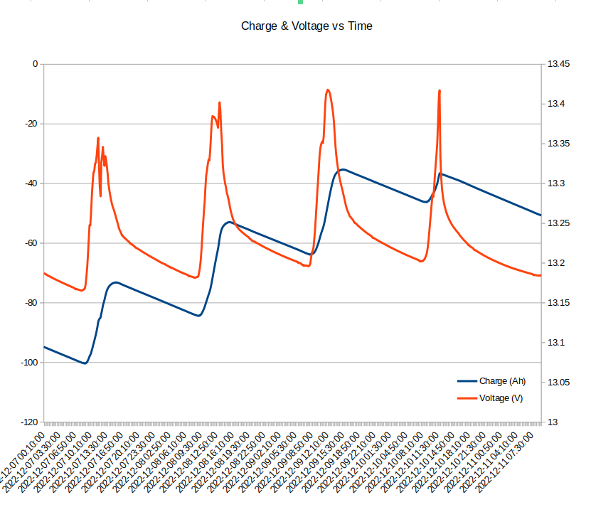
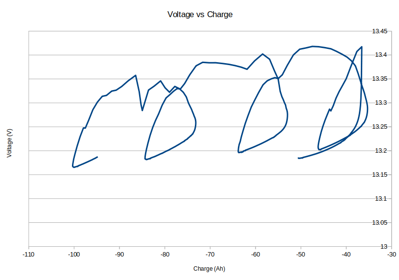
Some clean data at last. The same data is plotted on both graphs. Charging was from solar, discharge was from various fixed loads. On the fourth day, charging was stopped due to upper voltage limit being met.

-
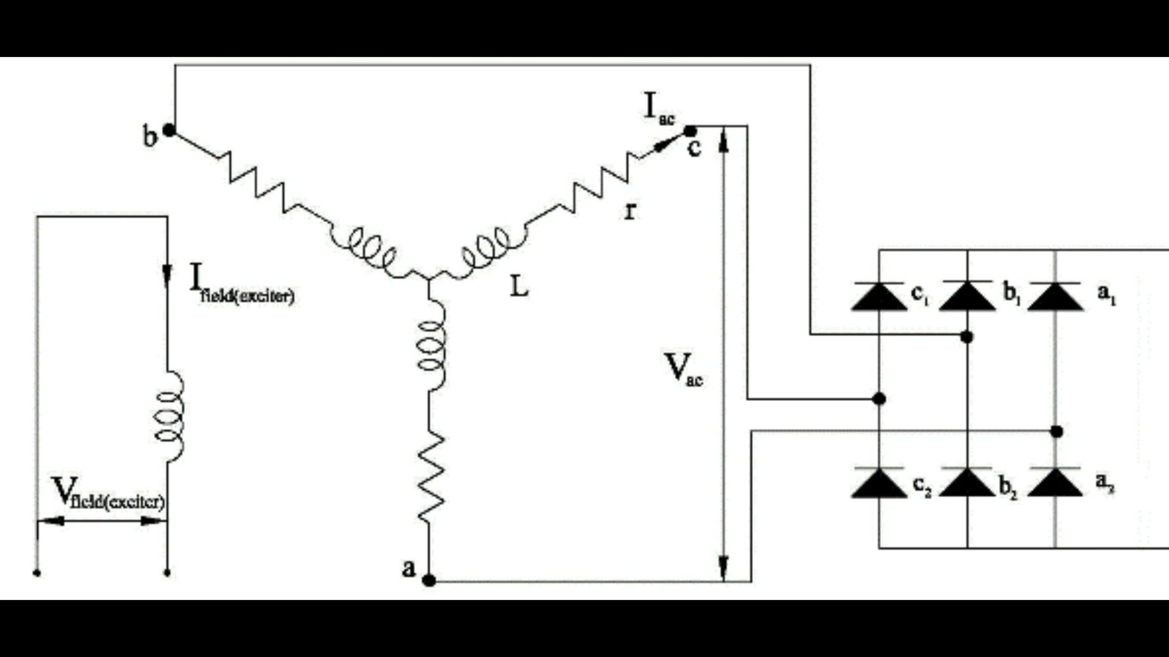
Just to add a bit of confusion to the conversation, the design of the main rectifier varies somewhat too. The traditional design for a 3 phase rectifier uses 6 diodes. However, the waveform shape at the input to the rectifier doesn't look anything like the sine waves we see in the textbooks. As a result the neutral point at the centre of the Y doesn't stay nicely centered at a mid point voltage. Instead it bounces around all over the place, and at times exceeds the supply rail voltages. So the designers capitalised on this by adding a 4th pair of diodes connected to the neutral. This small tweak can apparently recover up to an additional 10% more power. This scheme sometimes referred to as "3rd harmonic" rectification, presumably because the neutral bounces around at 3 times the fundamental frequency. Interestingly, the last time i replaced the diode pack on our alternator, was because this 4th pair of diodes had decided to phase change to the 4th state of matter. We only happened to notice the blackened remains of this diode pair when we had the alternator stripped down for an entirely unrelated reason. It had probably been like that for years. -- Craig
-
I have a vague recollection that back in the days when we used to use a handheld dmm to take cell measurements. The spreadsheet we recorded the results on would sometimes indicate an anomalous reading based on the sums of the cell voltages. I think we concluded that probing the nut gave unreliable results. It's been a while since we've had to take manual measurements and my memory is a bit hazy. Probing the terminal post propper started to cause damage to the insulating terminal covers. Then we decided enough was enough and automated the process. I suspect there might be some form of thermal junction or galvanic effect between dissimilar metals at the interface of the nut and terminal threads that causes voltage measurement error on the DMM. I did read somewhere (unable to find the link) that the nuts might have thread locking compound, but the fact that you've been able to rotate it suggests otherwise. I believe the nuts are made of zinc plated steel, and the terminal post is aluminium or copper.
-
Interesting teardown photos and description: https://liionbms.com/php/prismatic_cells.php Youtube video CALB Autopsy: Youtube video of CALB Resuscitation!
-
Yes, it doesn't seem logical, unless the terminal post is fractured within the nut. Or your DMM is acting up. Contaminated probe tips? I've read that the nuts can sometimes have thread locking compound applied, and therefore shouldn't be relied upon for an electrical connection. E.g when probing with a dmm. It would be interesting to see a cut away diagram of the inside of one of these cells. It might shed some light on the mystery. Thanks for posting... We'll bear it in mind in case anything similar happens to ours. Regards, Craig
-
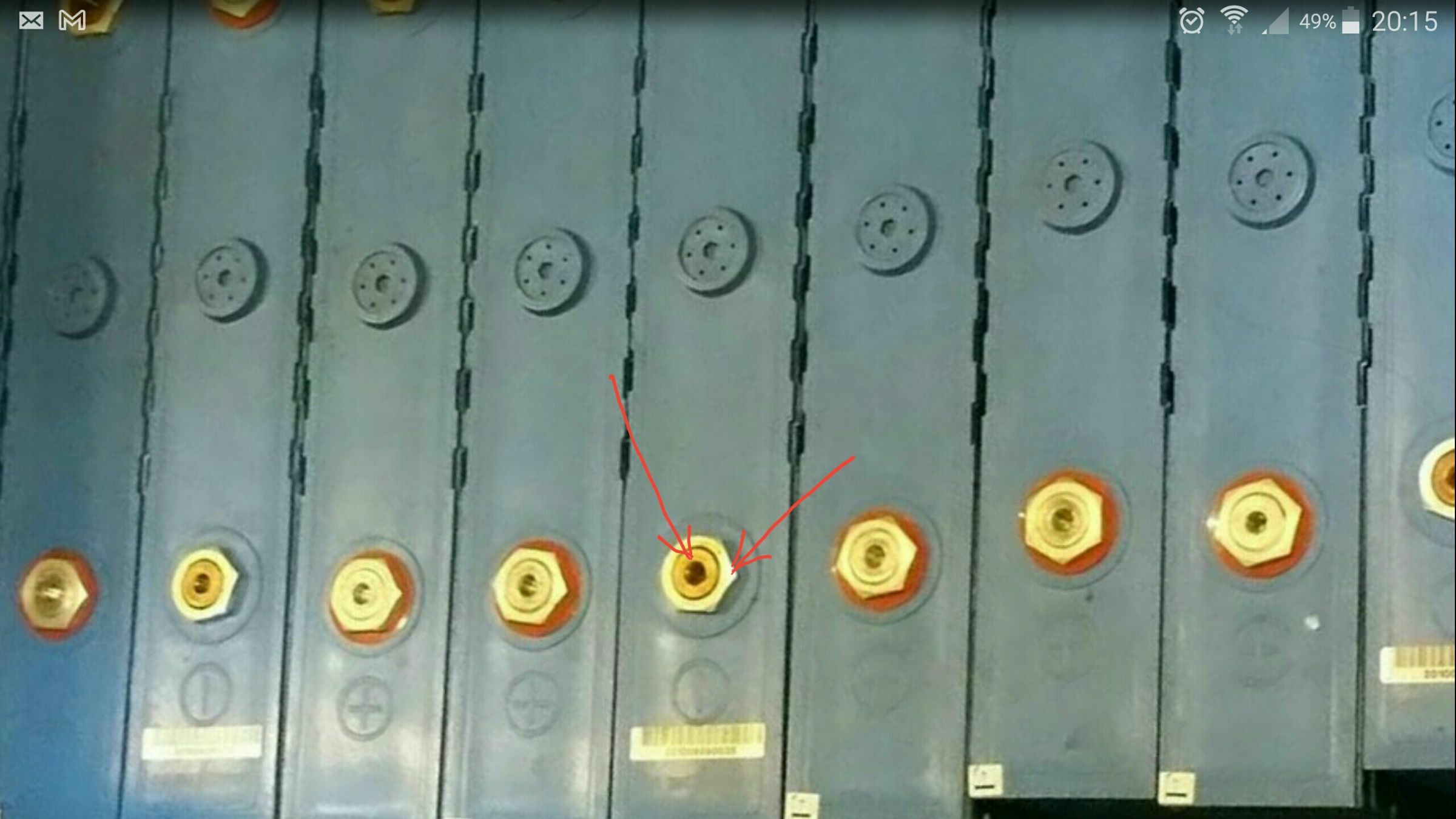
That's really strange. I always assumed the hex part was just a nut to stabilise the terminal against the case of the cell. So you saw a voltage drop between the two points arrowed below?
-
I just noticed that you have some additional lugs for your instrumentation on the 'dodgy' terminal. That's something we considered doing, but didn't like the idea of because it jacks the bolt out of the battery terminal, and causes the mechanical pressure of the bolt to be applied to a small area on the strap. In the end we ended up going for crocodile clips for the instrument wires, which certainly aren't great.
-
Get polishing! Hey, we've had a similar issue. It was especially visible on the temperature readout. From memory, the CALB manual does say that the terminals need to be polished each time the pack is reassembled. I think our issue started when we striped the pack down to relocate it. The terminals looked good enough so we just put it back together. The best method we found in the end was fine wet and dry paper backed with a block of wood to ensure the polished surface is flat. The copper at the centre of the terminals becomes a mirror finish. Same goes for the straps.
-
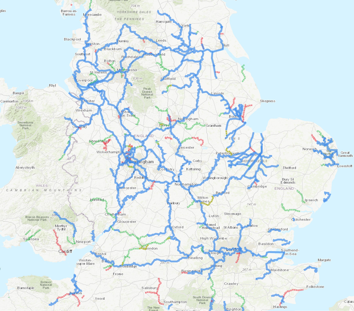
Hi, The link below is to a ZIP containing the HTML document and Javascript files. I was a little reluctant to share this via google drive as I cannot guarantee how long the link will remain live. Also I'm not too sure about the licencing terms. I'm aware that the Leaflet library is distributed under a BSD permissive licence. Since this off-line page loads its data from the feeds published by IWA, if ever those feeds change it will stop working. https://drive.google.com/file/d/1KaBVmV8ua3Le-KHoSwlUvdTBAtwso7hQ This is exactly the same map as is published on IWA, but with some personalisation of the style settings, different line colours etc. in map-v2.js I've only ever tested this on a PC using Firefox. Just make sure the files "IWA Map.html" "map-vendor.js" "map-v2.js" and "leaflet-2.css" are in the same directory on your computer, and open "IWA Map.html" in your web browser. I suppose theoretically, I could embed the CSS, and Javascript within the HTML document to possibly make it easier to use. It might work on a smartphone - I've not tested that though. Regards, Craig
-
This map is great. I've had it on my wall for several years now. We also have one on the boat, but had to cut it down to a more practical size. It's possible with a bit of snipping to get it down to A2, whilst still having the enlargement sections not obscuring anything. One thing that makes this map particularly useful is the inclusion of major roads. Also, it is possible with a bit of script modification to use the very nice map that the IWA publish via their website as a full-screen webpage with scroll-wheel zooming. Unfortunately, it is not possible to attach the .html .css and .js files here due to file-type restrictions. I've attached some screenshots, which ironically are about 10x bigger than the html/javascript. Edit: I forgot to mention that it also supports hovering over the waterways to show their name. The map display is just using a Javascript library called Leaflet.
-
Had another letter through the door today, stating that the policy expires on 4th of December 2021. Starting to get a bit confusing now.
-
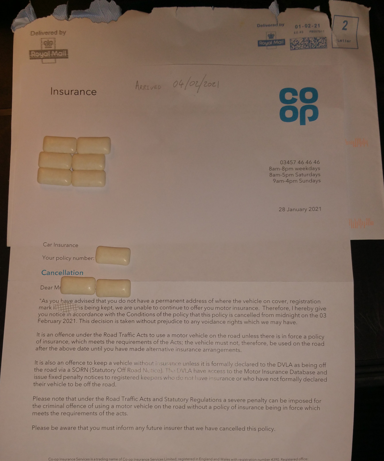
Hi, Sorry to reignite an old thread, but it looks like my dad has ended up being caught out by this trap. The letter (attached) arrived today 04/02/2021, saying that his car insurance had been cancelled yesterday 03/02/2021. With the poor weather recently, I though perhaps the letter had been delayed in the post? ... but the envelope was franked on 01/02/2021. Some weeks ago, my dad had to phone his car insurers for a completely unrelated reason but ended up mentioning that he was living on his narrowboat. He's been staying on the boat permanently recently because his girlfriend is working on the covid wards and he narrowly escaped getting infected at home during the first wave. He does have a permanent address, where he often does keep the car because the car becomes an inconvenience to him while he's cruising. During the lockdown it's been a bit different; boat movement has virtually ceased and with not wanting to use the trains and buses as much, he's preferred to keep the car close by. I guess he was telling the truth for the situation at this point in time. To be fair, he was told over the phone that his policy would be cancelled, and confirmation would be in writing. After a follow-up call to clarify his situation, they said they would forward his clarification to the underwriters. I'm guessing this letter states the underwriters final decision? As you can probably imagine this has now left him in a bit of a predicament. Any recommendations on a new insurer as we're guessing it's not going to be easy to find one now that he has had a policy cancelled? Best Regards, Craig
-
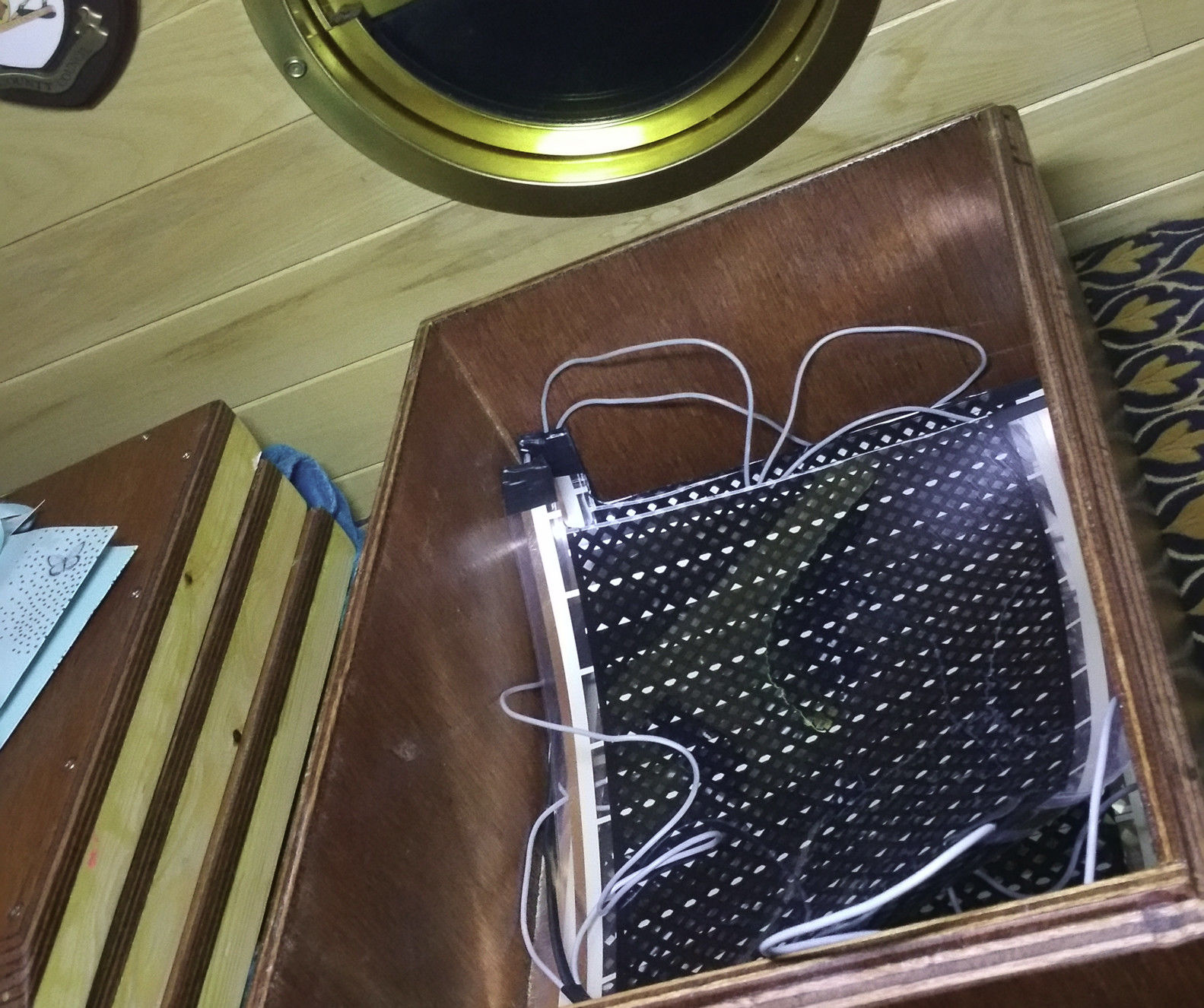
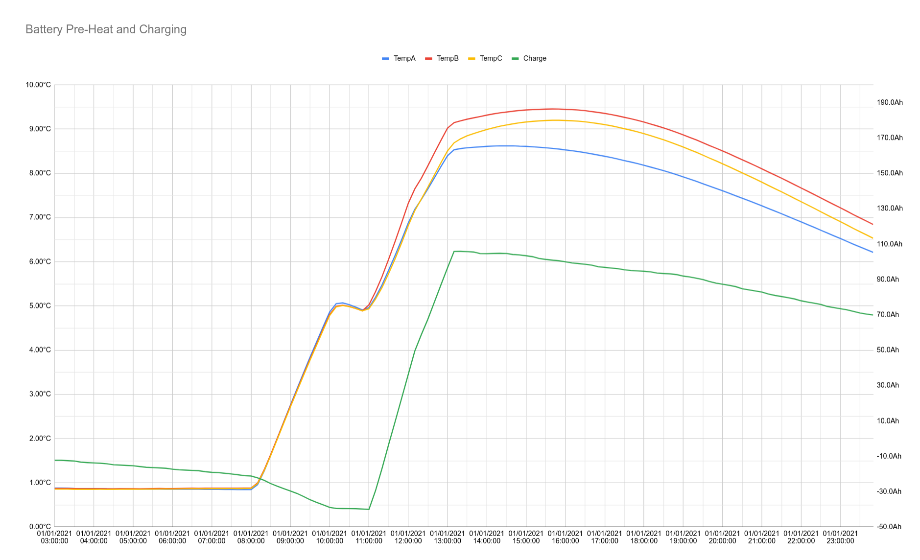
After digging back through the photos.. (memory not as good as it used to be) I can vaguely remember cutting through the transparent surface film with a scalpel. I can also remember it being possible to thread the wire in from the ends alongside the copper foil. I think the copper foil is only adhered to one side of the transparent film. I remember cutting a hole in the film part way along, to allow the wire to be soldered, either to the foil or back onto itself. You can see on the photo that I did a staggered cut of the sheet so that the connection point wasn't located directly beneath the batteries. The batteries sit directly on top of the heating film, with insulation beneath that. The sides of the batteries are also insulated, as are the lids of the enclosures. Until recently we didn't have much in the form of battery temperature monitoring, we just used to use the read-out on the solar charge controller, which had a single sensor on a long lead. In my previous post, I described the fact that we had wired all 3 heaters in series to limit the maximum power and make the system "inherently safe" I recently determined that this winter the series heater configuration would not be sufficient to heat the batteries in a sensible time period, and heating the batteries over a long period of time wasn't very efficient due thermal loss from our enclosures. We now have the heaters wired in a parallel configuration, with fuses rated at 7.5A on each of +ve and -ve as before. Each heater measures as approx 4.9 Ohms. Powering from 13V, with approx 0.4 Ohms of wiring resistance, we are able to dump about 22W of heating power into each battery. Approx 6.4A total. The attached graph shows the the temperature rise. The heaters were run for 2 hours, then turned off for 1 hour before charging the batteries using the alternator. The latter stage of charging was done at a lower engine RPM and the lower charging current this caused is evident in the graph. The graph shows the self-heating of the batteries during charging at a similar rate to what the heaters achieve. The thermal resistance per enclosure (leakage) was determined to be about 1.16 °C per W, and the heat capacity per enclosure was determined to be about 35.5kJ per °C. From these values it is possible to predict how much heating time is needed to raise the temperature by a given amount, and to determine the maximum achievable temperature etc... Depending on the design of your enclosures, wiring the heaters in parallel like this might not be inherently safe i.e. it might be possible to heat the batteries beyond their specification. I'd recommend installing an additional protection system such as thermal fuses, clockwork timer unit etc.. With our system, it is theoretically possible to heat the batteries to about 19 °C above the engine room temperature. We'll certainly be removing the fuses once the winter is behind us. -- Craig
-
I've tried to implement this, but due to various effects our long-term Ah counting has turned out to be not good enough. I'm hoping to make improvements over the next few weeks, but there's no guarantee that will overcome all of the long-term drift error which is inherent with this method. Charging to 100% periodically to reset the meter is one obvious solution, but you might not want to do that as often as is needed. The problem we found when using estimated SoC to stop the charging was that the numbers ended up looking too trustworthy and we lost our mental reference of SoC. We only realised that the SoC gauge had drifted out when the vacuum cleaner tripped the low voltage protection switch. This is despite the fact that we still had a trust-worthy volt meter. For some reason it was more satisfying to trust the Ah based SoC gauge. We then decided to charge to a known point just to see how far down they really were. The engine ended up running for over 6 hours! It was reminiscent the feeling of "suddenly realising you're lost" after figuring out that you've been misreading a map... for most of the day. In the end we opted for a simple approach of charging until a predetermined voltage, and then resetting the counter. This method is not perfect, but it is easy to live with the "known imperfection". The result is a variation in cut-off point due to temperature, charge current, and other factors but at least this is a variation on a fixed datum as opposed to something which can gradually drift with time. I was hoping to implement a SoC percentage gauge based on the battery voltage, which could then be used to null out the long-term drift in the Ah measurement. It turns out that this is non-trivial since the various factors are involved, primarily the history of charge/discharge currents. There are countless papers on this topic in the engineering/science journals. It's easy to overlook the fact that we've got by using just a simple volt meter for the first couple of years. My father used to take a glance at the meter first thing in the morning before the solar started to kick in. Using this approach he somehow got an approximate feel for the SoC. Also without realising it he also used to wait for an appropriate moment in the fridge compressor cycle. I imagine this is possibly the simplest approach to implement in software as instead of having a complex model to compensate for the effect of current, it's easier just to eliminate the effect by taking the voltage measurement at a carefully chosen moment.