
Leaderboard


Popular Content
Showing content with the highest reputation on 01/09/18 in all areas
-
It's not actually the date you last posted - it's the date you last posted something sensible! ?6 points
-
Should CRT ever get their way and remove old wider deeper boats from the system, they will then take a massive maintenance holiday from doing things like dredging and pulling out lock walls. Eventually the whole system will be <2ft deep with locks 6' 10" wide. At that point, all the pleasure boats whose owners scream blue murder if they as much as graze the bottom when coming into the side will have all the fun that ex working boat owners have had for years, but we won't be there anymore to find the rocks, shallow and tight bits and get CRT to do something about it before others have even noticed. George4 points
-
We mentioned it once, but I think we got away with it, Fawlty!2 points
-
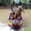
I've had solo male boater troubles, they seem to be a grumpy lot. To the extent that on the way north to Fenny Compton one told me to F off as soon as I pulled in behind him for no other reason than he wanted the mooring, big enough for 3 boats, all to himself. We cruised off for another quarter hour and found somewhere just big enough to moor. Then in the late evening I cycled back and threw bread on his roof, I bet the birds woke him up early! I'm warning all that are around that now I am old and curmudgeonly I have a zero tolerance, beware.2 points
-
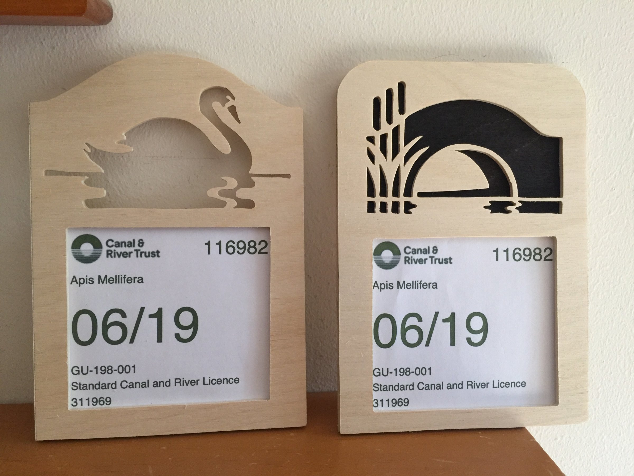
I like the old Logo of the C&RT and the British waterways, so I got on the scroll saw and cut these. Looks better than the old brittle plastic wallet that stuck on the window at the moment.
 2 points
 -
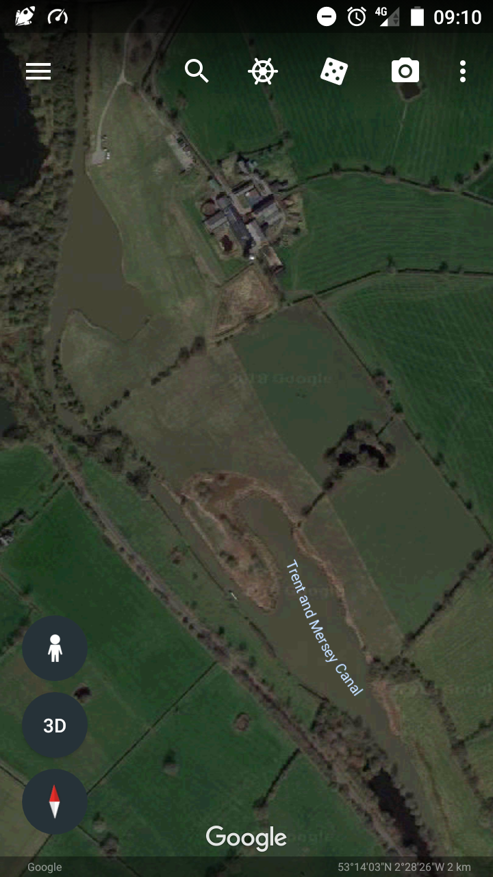
How doo all. I'm new to the forum but not to boats. I have grown up on them. And now after a savage medical discharge from the military me and my wife are living aboard. Any who, i was hoping someone could tell me about the hulks scuttled in the collapsed salt mines Middlewich way. I have always admired them and just curious if anyone has some solid gen and even pictures?
1 point
-
I bought some last year and did my water tank with it. And lived to tell the tale (so far anyway)! The very helpful and knowledgeable lady in the chandlery at Braunston bottom lock convinced me it was an issue of certification change, not formulation. I believed her, in part because she also talked me out of spending money on an unrelated item. I like it when retailers, tradesmen etc do that, it makes a refreshing change from people trying to upsell.1 point
-
Is it the same as Network Rail bridge paint? That is also grey and seems to last brilliantly.1 point
-
This post cannot be displayed because it is in a forum which requires at least 10 posts to view.
-
This post cannot be displayed because it is in a forum which requires at least 10 posts to view.
-
... round the M25 and fill it with water ...1 point
-
Hi Mike. You are right about the layers being a substrate for a quality finish. Primers provide a key to the base material, while undercoats also provide a colour base for later glosses. Many gloss colours have little covering power on their own, dark blues being particularly weak in this respect. Aware of this, one yard recently used a black undercoat before applying midnight blue gloss.. Its about building depth of paint thickness too, a good few problems with paint jobs are down to insufficient thickness of applied paint. Manufacturers often specify a minimum thickness of so many microns. I don’t have figures to hand, sorry.1 point
-
Did you complain about the vegetation? Hopefully CRT will do something if they get lots of complaints. If anyone wants to complain I've looked up the appropriate contact details so you don't have to! I complained online here: https://canalrivertrust.org.uk/contact-us/ways-to-contact-us Or you can phone on 0303 040 4040. Or use Twitter, if you are that way inclined... @CRTcontactus See below for extract from the CRT website (I believe this applies equally to bankside vegetation). I think we can all (those of us who have witnessed it) agree that what is going into the water constitutes "unreasonable amounts"! Grass cuttings in water Our contractor is instructed not to allow grass clippings to enter the water, however small amounts of clippings will inevitably enter the water. A failure to prevent unreasonable amounts of clippings entering the water is a breach of the Code of Practice as agreed by the contractor – as such they will be penalised and requested to remove the clippings. Pplease contact us online or call us on 0303 040 4040 to report any incidents.1 point
-
Anyway, 99% of folk automatically, always, as a matter of course, or subconsiousely switch both isolator switches on BEFORE starting the engine. There's always going to be a 1% of goons that forget, don't, or think they know better. I think TB's diagram is lovely, as good as the LT underground railway map any day, although mainly Central line.1 point
-
This post cannot be displayed because it is in a forum which requires at least 10 posts to view.
-
This post cannot be displayed because it is in a forum which requires at least 10 posts to view.
-
First of all the diagram is for one specific boat that probably has another positive connection to the domestic fuse box and it's bus bars. What did you not understand about the rising voltage would close the VSR & present the engine battery as the load. What do you not understand about "the danger is disconnecting a running alternator from the load, not energising one when open circuit. It takes time, maybe not much but still time for the voltage on the alternator to rise as it energises where as an open circuit is instantaneous. That time gives the regulator plenty of time to clamp the voltage thus preventing spikes. In fact that alternator may well contain a zener diode specifically to clamp any voltage spike to a safe level. I agree the generating part of the alternator is three phase but once it has passed all three sets of diodes its DC with a ripple on top with, once the regulator has started working an RSM (if you can say that bout ripply DC) of about 14 to 14.2 volts in this case. The thing that does the damage when a RUNNING alternator is open circuited is the almost immediate collapses of the stator magnetic field inducing one large voltage spike. There will not be a sudden collapse if its started open circuit. I am not willing to waste any more time of this theoretical and pointless debate. The diagram is as far as I know the best compromise for the OP.1 point
-
This post cannot be displayed because it is in a forum which requires at least 10 posts to view.
-
Photos candidate for Moored Like A Tw(i)t FB group?1 point
-
Would TI's LM2917 be of any use in this context?1 point
-
Good spot! Says they all have new glow plugs, which alone costs fifty quids.1 point
-
This post cannot be displayed because it is in a forum which requires at least 10 posts to view.
-
This post cannot be displayed because it is in a forum which requires at least 10 posts to view.
-
Most boat systems I have seen have been vented with an open header tank, so hopefully the worst you get is superheated steam and scolding water flying about the boat.. IMO Fully pumped systems without a gravity radiator are an accident waiting to happen1 point
-
Canalplan has a user contribution as well and you could ask the same questions.1 point
-
This post cannot be displayed because it is in a forum which requires at least 10 posts to view.
-
I should get a greeno for activating it don't you think? i will add Old Hill (Hawne Basin), Langley Green (Titford Pumphouse) and Tipton (BCLM) to that list next week. Plus I guess the rather more obvious Birmingham New St and Droitwich. JP1 point
-
The 'link' isn't. At least for me it's not anyway. I often use the train to get to and from canals. JP ETA - it works in my quote of your post but not in your original post!1 point
-
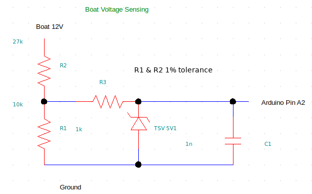
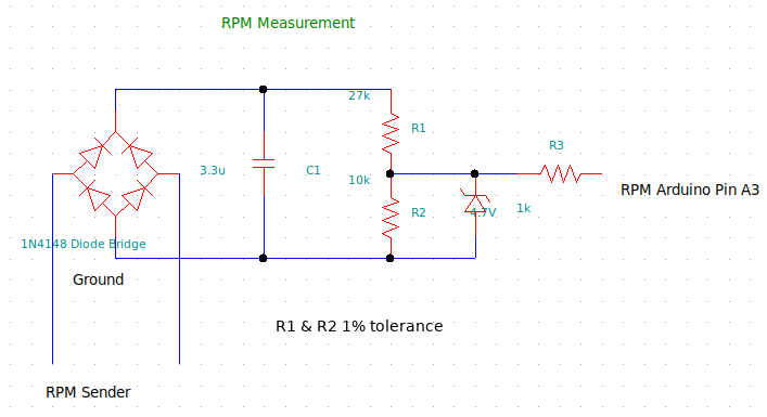
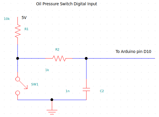
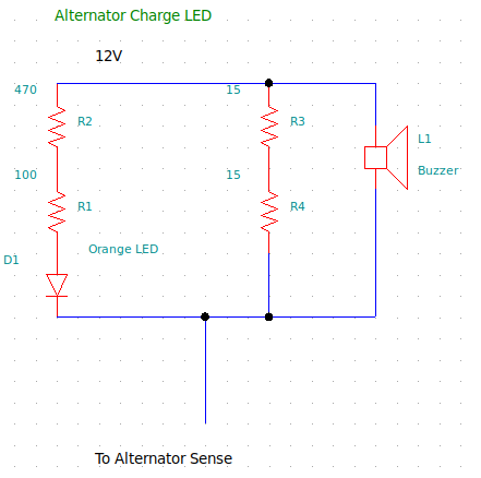
Thank you! The panel is now in and so far, working OK. Don't have a photo yet of it installed. For anyone interested in doing something similar, here are some of the design decisions and circuits used. As has been mentioned before in this thread, boats are electrically very noisy environments. Pumps, motors, relays, alternators, radios are all putting noise and voltage spikes in to the supposedly DC wiring. Delicate low voltage, low current electronics needs protecting against this if weird results, or device destruction is to be avoided. I stole some ideas from the early Bedazzled LED's I have on my boat and also from the Megasquirt project, which is an open source vehicle engine management system. These products have been designed for boat and the similar automotive environment. There is a 22V metal oxide varistor on the 12V input into the 12V to 5V DC-DC convertor. This safely dumps any high voltage spikes, either negative or positive to earth. Protecting the 5V Arduino there is a 5V transient voltage suppressor on the output from the DC-DC convertor. There is another on the resistor voltage divider in to one of the analogue inputs used to measure boat voltage. There are capacitors on the digital and analogue input lines to filter out any high frequency signals induced in to the lines. Most resistors are standard 5% tolerance carbon film. The ones used for voltage divider resistor networks are 1% tolerance metal film type. I've attached pictures of various input circuits below. Also below is the sketch for the Arduino Leonardo for anyone who is interested. Feel free to copy and modify to suit. All this stuff will almost certainly need altering to suit the senders on your boats engine. Jen /*A digital instrument set for boat Delta Lady. Written by Jen-in-Wellies, June-July 2018. Displays on a 20x4 character LCD using an I2C interface adaptor. Uses an Arduino Leonardo PLC as this doesn't use analog-in pins for the IC2 interface, like the Uno and gives six available for analogue inputs, instead of four. Displays RPM, water temperature, oil pressure, voltage and fuel level. Displays warnings when oil pressure is too low or high, water temp is too high, voltage is too low or high and fuel level is too low. Lights LED's and sounds buzzer for these warnings as appropriate. Automagic day/night LCD backlight illumination using Light Dependent Resistor (LDR). */ #include <LiquidCrystal_I2C.h> //Library for liquid crystal displays driven by I2C two wire bus #include <Wire.h> //Library for I2C 2 wire bus to drive the liquid crystal display. #include <EEPROM.h> //Library so EEPROM can be used to store engine hours. /* SDA to the I2C adaptor goes to SDA pin on the Leonardo and SCL to SCL pin These are also on pins D2 and D3, so don't use these for anything else. Similarly, pins D0 and D1 can't be used as they are also for serial data when debugging.*/ LiquidCrystal_I2C lcd(0x27, 20, 4); //Address 0x27, 20 characters by 4 rows. //Define variables for analog inputs. int tempIn = 0; //Temperature input from analog in. 0 to 1024. int oilIn = 0; //Oil pressure input from analog in. 0 to 1024. int voltIn = 0; //Voltage input from analog in. 0 to 1024. int rpmIn = 0; //Engine rrpm input from analog in. 0 to 1024. int dieselIn = 0; //Fuel level from analog in. 0 to 1024. int ldrIn = 0; //Cabin ambient light level from analog in. 0 to 1024. //Define variables for digital inputs. int oilDin = 0; //Oil pressure switch input. /*Calculated values to go to LCD. Floating point for required precision for calculation and display Except LDR, where it isn't important. */ float tempOut = 0; //Calculated water temperature. float oilOut = 0; //Calculated oil pressure. float voltOut = 0; //Calculated engine voltage. float rpmOut = 0; //Calculated engine RPM. float dieselOut = 0; //Calculated fuel level. //int ldrOut = 0; //Output to LCD backlight. byte hoursAddress = 0; //EEPROM address to store engine hours. float engineHours; //engine hours stored in EEPROM hoursAddress //Define time measurement variables for updating engine hours. uint32_t ts1 = 0; uint32_t ts2 = 0; //Define analog input pins int tempPin = A0; //input from coolant temperature sender. int oilPin = A1; //input from oil pressure sender. int voltPin = A2; //input from 12V system voltage divider. int rpmPin = A3; //input from AC rpm sender bridge rectifer. int dieselPin = A4; //input from fuel tank sender. int ldrPin = A5; //input from light dependent resistor. Ambient light. //Defining output digital pins. int oilWarn = 4; //Oil pressure warning LED pin. int tempWarn = 5; //Water temperature warning LED pin. int voltWarn = 6; //voltage warning LED pin. int dieselWarn = 7; //Low fuel warning LED pin. int buzzwarnA = 8; //Warning buzzer output pin A. int buzzwarnB = 9; //Warning buzzer outpin pin B. //Define input digital pins. int oilDpin = 10; //Input from oil pressure switch. //Characters to display floating points to the required precision on the LCD char engineHoursdisplay[15]; char rpmOutdisplay[15]; char tempOutdisplay[15]; char oilOutdisplay[15]; char voltOutdisplay[15]; char dieselOutdisplay[15]; //various constants const int oilMin = 15; //Minimum oil pressure warning value PSI. const int oilMax = 85; //Maximum oil pressure warning value PSI. const int tempMax = 105; //Maximum coolant temperature warning value C. const int voltMin = 12; //Minimum voltage warning value. const int voltMax = 15.5; //Maximum voltage warning value. const int dieselMin = 10; //Minimum fuel tank warning level value. const int ldrThreshold = 400; //ldrIn value to switch backlight on/off. Higher is darker. int buzzWarn = 0; //Sound buzzer when set to >0 (1). //Equation values. const float rpmM = 4.554; //m part of the y=mx+c linear equation for converting Analogue in to rpm displayed. const float rpmC = 215.706; //c part of the y=mx+c linear equation for rpm. //Voltage divider resistors units are 10^3ohms to minimise interger values and overflow risk. //Dimensionless as divider ratio is (voltR1+voltR2)/voltR2. //const int rpmR1 = 27; //kohms //Rpm voltage divider resistors. //const int rpmR2 = 10; //kohms const int voltR1 = 27; //kohms //Voltage sensing divider resistors. const int voltR2 = 10; //kohms const float tempB = 0.000786; //B multiplier parameter for temperature resistance curve. const float tempR = 0.000942; //r offset parameter for temperature resistance curve. float tempR2 = 0.0; //calculated resistance of temperature sender. const float tempR1 = 220.0; //voltage divider resistor for temp sender. const float oilM = -0.243; //M multiplier for oil pressure linear equation const float oilC = 178.543; //C offset for oil pressure linear equation float oilR2 = 0.0; //Calculated resistance of oil sender. const float oilR1 = 100.0; //voltage divider resistor for oil sender. const float dieselM = 1; //M multiplier for diesel level linear equation. const float dieselC = 0; //C offset for diesel level linear equation. float dieselR2 = 0.0; //Calculated resistance of diesel sender. const float dieselR1 = 100.0; //Voltage divider resistance for diesel level oil sender. void setup() { // put your setup code here, to run once: // Define digital outputs for warning LED's and buzzer. pinMode(oilWarn, OUTPUT); pinMode(tempWarn, OUTPUT); pinMode(voltWarn, OUTPUT); pinMode(dieselWarn, OUTPUT); pinMode(buzzwarnA, OUTPUT); pinMode(buzzwarnB, OUTPUT); //Define digital input pin for pinMode(oilDpin, INPUT); //External pullup resistor used. //Initialise warning LED's and Buzzer. digitalWrite(oilWarn, LOW); //lOW turns it off. digitalWrite(tempWarn, LOW); digitalWrite(voltWarn, LOW); digitalWrite(dieselWarn, LOW); digitalWrite(buzzwarnA, LOW); digitalWrite(buzzwarnB, LOW); // initialise the lcd lcd.init(); //3 blinks of LCD backlight and LED's, except alternator warning which is 12V and seperate. for (int i = 0; i < 3; i++) { lcd.backlight(); digitalWrite(oilWarn, HIGH); digitalWrite(tempWarn, HIGH); digitalWrite(voltWarn, HIGH); digitalWrite(dieselWarn, HIGH); delay(250); lcd.noBacklight(); digitalWrite(oilWarn, LOW); digitalWrite(tempWarn, LOW); digitalWrite(voltWarn, LOW); digitalWrite(dieselWarn, LOW); delay(250); } //Get current engine hours. EEPROM.get(hoursAddress, engineHours); //Initialise time counter for engine hour updating. uint32_t ts1 = millis(); /*//Debug serial port monitoring. Comment out for production. //Must have laptop connected and serial monitor running if uncommented, //or the Arduino hangs at this point waiting for the serial port to connect. Serial.begin (115200); // Leonardo: wait for serial port to connect while (!Serial) { }*/ } void loop() { // put your main code here, to run repeatedly: //Read analog sensors. tempIn = analogRead(tempPin); oilIn = analogRead(oilPin); voltIn = analogRead(voltPin); dieselIn = analogRead(dieselPin); rpmIn = analogRead(rpmPin); ldrIn = analogRead(ldrPin); //Read digital sensors oilDin = digitalRead(oilDpin); //Check engine hours count and update every 0.1 hour. uint32_t ts2 = millis(); if (ts2 - ts1 >= 360000) { ts1 = ts2; EEPROM.put(hoursAddress, engineHours + 0.1); engineHours = engineHours + 0.1; } //Calculations for engine voltage, oil pressure, water temperature, LDR and RPM. //Use *.0 for constants to force calculation in to floating point mode, except LDR where it doesn't matter. voltOut = voltIn * 5.0 * (voltR1 + voltR2) / (voltR2 * 1023.0); //Engine voltage calculation. Resistor based voltage divider. //Calculate oil sender resistance. //oilR2 = oilR1 * 1023 / (1023 - oilIn); oilOut = oilM * oilIn + oilC; //Oil pressure calculation. //Calculate temp sender resistance. tempR2 = tempR1 * 1023 / (1023 - tempIn); tempOut = (1 / ((tempB * log10(tempR2)) + tempR)) - 273.0; //Temperature calculation. //Calculate fuel sender resistance. dieselR2 = dieselR1 * 1023 / (1023 - dieselIn); dieselOut = dieselIn * dieselM + dieselC; //Fuel level calculation. Awaiting calibration data. //RPM calculation. Linear equation. rpmOut = rpmM * rpmIn + rpmC; //Set LCD backlight according to the ambient light level detected by the LDR. if (ldrIn <= ldrThreshold) { lcd.backlight(); } else { lcd.noBacklight(); } //Convert floating point values to the required precision and put them in to strings to display on the LCD. dtostrf(engineHours, 5, 1, engineHoursdisplay); dtostrf(rpmOut, 4, 0, rpmOutdisplay); dtostrf(tempOut, 3, 0, tempOutdisplay); dtostrf(oilOut, 3, 0, oilOutdisplay); dtostrf(voltOut, 2, 1, voltOutdisplay); dtostrf(dieselOut, 3, 0, dieselOutdisplay); //Debug readout to serial monitor. /*Serial.print("oilDpin "); Serial.println(oilDpin); Serial.print("Engine Hours "); Serial.println(engineHoursdisplay); Serial.print("RPM In "); Serial.print(rpmIn); Serial.print(" Out "); Serial.print(rpmOut); Serial.print(" Display "); Serial.println(rpmOutdisplay); Serial.print("Temperature In "); Serial.print(tempIn); Serial.print(" Out "); Serial.print(tempOut); Serial.print(" Display "); Serial.println(tempOutdisplay); Serial.print("Oil Press In "); Serial.print(oilIn); Serial.print(" Out "); Serial.print(oilOut); Serial.print(" Display "); Serial.println(oilOutdisplay); Serial.print("Voltage In"); Serial.print(voltIn); Serial.print(" Out "); Serial.print(voltOut); Serial.print(" Display "); Serial.println(voltOutdisplay); Serial.print("LDR In "); Serial.println(ldrIn); //Serial.print("OilIn "); //Serial.println(oilIn); //Serial.print("Oil R1 "); //Serial.println(oilR1); //Serial.print("Oil Sender Resistance OilR2 "); //Serial.println(oilR2); Serial.print("tempIn "); Serial.println(tempIn); Serial.print("tempR1 "); Serial.println(tempR1); Serial.print("Temp Sender Resistance tempR2 "); Serial.println(tempR2); delay(4000); //Delay so above can be read.*/ //Display results on the LCD. lcd.clear(); //Display RPM. lcd.setCursor(0, 0); lcd.print("Engine"); lcd.setCursor(7, 0); if (rpmOut < 300) { lcd.print("0"); } //Set display RPM to 0 if it is low to get round tolerance errors with a stopped engine. else { lcd.print(rpmOutdisplay); } lcd.setCursor(11, 0); lcd.print("rpm"); /*//Display fuel level. lcd.setCursor(16,0); lcd.print(dieselOutdisplay); lcd.setCursor(19,0); lcd.print("l");*/ //Display water temperature. lcd.setCursor(0, 1); lcd.print("Water"); lcd.setCursor(7, 1); lcd.print(tempOutdisplay); lcd.setCursor(11, 1); lcd.print("degC"); //Display oil pressure. lcd.setCursor(0, 2); lcd.print("Oil"); lcd.setCursor(7, 2); lcd.print(oilOutdisplay); lcd.setCursor(11, 2); lcd.print("PSI"); //Display Voltage lcd.setCursor(0, 3); lcd.print(voltOutdisplay); lcd.setCursor(4, 3); lcd.print("V"); //Display engine hours. lcd.setCursor(7, 3); lcd.print(engineHoursdisplay); lcd.setCursor(14, 3); lcd.print("Hrs"); //Warning LED's, LCD display and buzzer for engine problems with voltage, oil, water, or diesel tank. //Voltage if (voltOut > voltMax) { digitalWrite(voltWarn, HIGH); lcd.setCursor(14, 3); lcd.print("*HIGH*"); buzzWarn = 1; //sound buzzer } else { digitalWrite(voltWarn, LOW); } if (voltOut < voltMin) { digitalWrite(voltWarn, HIGH); lcd.setCursor(14, 3); lcd.print("*LOW*"); buzzWarn = 1; } else { digitalWrite(voltWarn, LOW); } //Oil Pressure if ((oilOut > oilMax) && (rpmOut < 200)) { digitalWrite(oilWarn, HIGH); lcd.setCursor(14, 2); lcd.print("*HIGH*"); } else { digitalWrite(oilWarn, LOW); } if (((oilOut < oilMin) || (oilDin = LOW)) && (rpmOut < 200)) { digitalWrite(oilWarn, HIGH); lcd.setCursor(14, 2); lcd.print("*LOW*"); } else { digitalWrite(oilWarn, LOW); } if ((oilOut > oilMax) && (rpmOut >= 200)) { digitalWrite(oilWarn, HIGH); lcd.setCursor(14, 2); lcd.print("*HIGH*"); buzzWarn = 1; } else { digitalWrite(oilWarn, LOW); } if (((oilOut < oilMin) || (oilDin = LOW)) && (rpmOut >= 200)) { digitalWrite(oilWarn, HIGH); lcd.setCursor(14, 2); lcd.print("*LOW*"); buzzWarn = 1; } else { digitalWrite(oilWarn, LOW); } //Water temperature. if (tempOut > tempMax) { digitalWrite(tempWarn, HIGH); lcd.setCursor(14, 1); lcd.print("*HIGH*"); buzzWarn = 1; } else { digitalWrite(tempWarn, LOW); } /*//Diesel fuel low level in the tank. if(dieselOut < dieselMin){ digitalWrite(dieselWarn, LOW); }*/ //Either sound warning buzzer delay 1sec. if (buzzWarn > 0) { buzz(); } else { delay(1000); // update each second } buzzWarn = 0; } //Warning Buzzer. Set up buzz function with 4kHz frequency for half sec, delay half sec. void buzz() { long elapsed_time = 0; while (elapsed_time < 500000) { digitalWrite(buzzwarnA, HIGH); digitalWrite(buzzwarnB, LOW); delayMicroseconds(125); digitalWrite(buzzwarnA, LOW); digitalWrite(buzzwarnB, HIGH); delayMicroseconds(125); elapsed_time += 250; } delay(500); }
1 point
-
The aluminium control panel arrived today. Made from our CAD file by a local company that specialise in instrument panels. Engraved legends, coloured a nice blue. Very reasonably priced considering the work involved. I've assembled the various components on the back and everything fits! A nervous moment as we had one go to get this right... Jen The key switch and horn button are still on the old panel. The photo of the front is out of focus and the lens on my phone is reflected in the lexan "glass" over the display.
1 point
-
There are 2 parts of the south Oxford that are canalised rivers. We always have the anchor ready for those sections. They can also ne useful when moored in a town - drop it down the off side so if the helpful locals untie you you won't go too far.1 point


This leaderboard is set to London/GMT+01:00