


nicknorman
Patron-
Posts
22,144 -
Joined
-
Last visited
-
Days Won
119

nicknorman's Achievements
")
-
At my caravan I have a single 100w panel. I used to have a PWM controller, recently I got a Victron MPPT and the output is much better. The panel voltage seems to settle at around 18v, open circuit is around 20v. So a single panel isn’t necessarily “12v”.
-
This post cannot be displayed because it is in a forum which requires at least 10 posts to view.
-
This post cannot be displayed because it is in a forum which requires at least 10 posts to view.
-
The load output is a bit of an odd thing, it is designed to operate eg a light that comes on at night. So it is less about “excess power” and more about using power for something that is dependant on having enough power available. In the context of a narrowboat it is best ignored.
-
This surely is the crux of my point. There are 2 choices, one being to tie your boat up sloppily and expect everyone else to compensate for that by passing at a crawl. The other is to spend an extra 2 minutes tying your boat up properly and then not expect everyone else to pass at a crawl. Personally I think that following a strategy which doesn’t place a burden on other people is the better one, but other opinions are available!
-
General rule is you should be able to twist the belt through 90degrees mid-span with moderate force. The belt will always squeal under heavy load at low rpm, so keep the revs up well above idle when under heavy electrical load eg washing machine heater. The lower the rpm, the more load on the belt.
-
I wouldn’t like to CC on rivers like the Ouse around York - too much flooding potential. The Selby canal has potential for mooring but whether that would satisfy the board I don’t know. Not too sure about the canalised portions of the Aire but I think winter flooding would still be a worry.
-
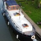
Slightly sub-optimal I would say, because the rope can circulate through the ring. Better to have effectively 2 separate ropes, one to the ring and back and one to the other ring (and back, if long enough). This is how I have done it. Front is just tied normally as it is where we normally embark/disembark and the boat is constrained for fore-aft movement by the 2 lines at the stern.

-
Moored at Westport Lake, just had a few boats going past and all set our boat bouncing and banging somewhat. Were they going too fast? Not really. The mooring ring spacing is sub-optimal. So I have just been out and added a spring at the stern, ie taken a line forward to the next ring, and tightened the ropes properly so the boat can’t move fore/aft. Took about 2 minutes. Now another boat has just come past, fairly fast. Our boat didn’t move at all. How often do you see boats moored with a spring? Hardly ever. So I say that every person who shouts “SLOW DOWN” or even thinks of doing so, or likes to whinge about boats passing too fast on here, only does so because they don’t know how to tie their boat up properly. (With possible dispensation for being moored on pins).
-
Sometimes you can have too much choice!
-
We are awaiting a visit from Jeff’s parents, then heading up the Caldon with them. Passing the H.I. and we might have to stop…
-
Westport Lake visitor moorings (Stoke on Trent) 3 boats moored this morning, one of which is ours. Having turned at Harecastle tunnel and chatted to tunnel keeper, she said 3 boats came through, all hire boats and all non-British crew. So it seems that while the Brits like to go to Benidorm for their summer hols, the Europeans like to visit Stoke on Trent. Which to be fair is quite similar to Benidorm bar the weather.
-
Well in that particular case, we had already drained the lock and driven the boat in and opened the appropriate paddles ( bearing in mind Stenson is one of the few wide locks where you open opposite side ground paddle first). So it must have been pretty obvious. Encountered that just yesterday at Planet lock, Caldon. On arrival there was a boat in the lock coming up. He opened the top paddles and then disappeared inside as I walked up to the lock. I sat on the balance beam and then started to open it, at which point his boat started moving forwards as it was in gear. I was momentarily alarmed thinking I shouldn’t have helped open the gate, but then he appeared, lowered the offside paddle and drove out. Presumably he was sat inside waiting to see the boat start to move, then came out. Quite cool I thought, although personally I wouldn’t be inside in a lock with no-one outside whilst it was filling. Although I love a good anti-volockie rant, it also has to be said that there are some good ones. This morning we went from Westport Lake, to Harecastle tunnel entrance just to turn round and dump rubbish. A young (relatively) volunteer tunnel keeper of female disposition came over for a chat, she was very pleasant and interested and presented a good customer facing image of CRT. Makes a change from the usual taciturn grumpy grey-beardy limpy old men!
- 50 replies
-
- 2
-

-
- vlockie instructions
- operating locks
- (and 1 more)
-
Yes I know the feeling! And I think they rely on most people not wanting a scene. But the more control freak volockies are tolerated, the more they feel empowered. I had that at Stenson once, went to open the top gate and the micromanaging volockie said “No, it isn’t ready until the water level (inside the lock) reaches this mark”. I pushed anyway and of course it opened, because it is nothing to do with the level inside the lock, only to do with the difference in levels, and the pound was slightly down. This is the sort of intelligence and competence that one has to deal with with some volockies! No idea of the big picture, everything done by numbers.
- 50 replies
-
- 3
-

-
-
- vlockie instructions
- operating locks
- (and 1 more)
-
You didn’t see the stoppage notice about the blocked canal just above Marston Doles? (just joking!)

