nicknorman
Patron-
Posts
21,880 -
Joined
-
Last visited
-
Days Won
119
Content Type
Profiles
Forums
Events
Gallery
Blogs
Store
Everything posted by nicknorman
-
We were in Tixall last week, oodles of space. In fact this was problematic because it was too difficult to decide which bit to moor at. It is so much easier when there is just 1 space!
-

Arco Zeus regulator - first impressions and a look inside
nicknorman replied to cheesegas's topic in Boat Equipment
The duty cycle limit (actually, a field current limit in my case) has some “ramping” (ie low pass filtering) applied on the way up, but not on the way down. So if the rpm goes up the field current limit will ramp up slowly, but if the rpm goes down it will rapidly reduce the field current limit, to avoid a transient high mechanical load. This seems to avoid any issue with noticeable “hunting”. And anyway there are still a lot of counts between idle (850 engine rpm) and 1300rpm - the latter being the point at which field current restriction is lifted - so even without the ramping I don’t think hunting would be noticeable. -
Arco Zeus regulator - first impressions and a look inside
nicknorman replied to cheesegas's topic in Boat Equipment
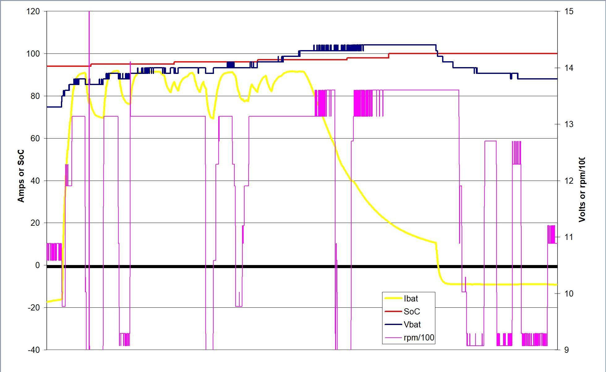
On the speed resolution thing, this is just a feature of the LIN interface standard not the internal workings of the chip. The data field is 8 bits but it is somewhat logarithmic so the alternator rpm that I am operating at is way up near the top where each bit is worth a lot of rpm. It is annoying because one can burn some programmable "OTP fuses" on the chip to specify the number of poles, which would bring the reported alternator rpm down to mid-range where the resolution is much better. But unfortunately for some reason I still dont understand, NXP don't include how you do this on the data sheet (only that you can do it, and give you the bits to change) and refused to tell me when I asked nicely. Still, it is of no real consequence as it doesn't affect the operation of the device beyond the logging data. I really only included the graph to make you jealous of the "taking full charge whilst at 98% SoC" thing that lithium batteries do!😁 -
Arco Zeus regulator - first impressions and a look inside
nicknorman replied to cheesegas's topic in Boat Equipment
Been down to the boat for a few days, thought I would generate some log data. The voltage and rpm data comes from the regulator chip - and the communication protocol does rather limit the resolution - and from the Mastershunt for the current and SoC. Graphs can be difficult to read when they have several different parameters but hopefully one gets the idea that the scale for current and SoC is on the left, and for volts and rpm on the right. I factored rpm by 100 to make it work alongside voltage. The batteries are already well charged at around 94%. At the LH side of the graph I flick the target SoC switch to 100% and it begins charging. We are cruising and rpm is up and down for moored boats etc, since the setup is on field current limit to 2A, the charge current varies quite a lot according to rpm. But note that the current remains at 75 to 95A until the SoC is 97% - the joys of Li! In fact you can see that the SoC jumps from 98% to 100% as the Mastershunt synchronises itself when the current falls to 5% capacity for a couple of minutes. So in fact, the SoC where the current starts to fall was around 98.5%! When the system detects fully charged (current below 5% for a couple of minutes) the regulated voltage changes to 13.3 which is less than battery voltage, so you can see the battery current is negative (discharging) and alternator output is zero. However the rpm readout from the chip is unaffected due to the "phase keep alive" function I mentioned previously. Whether the phase output would also be enough to operate a tacho I am not so sure. Oh and you can see there is a lot of smoothing on the current trace, this is a function of the Mastershunt. I really should use the BMV712 current which is much more instantaneous, but this “currently” only goes to the BMS, it doesn’t get passed on to the regulator. I’ll need to change the code a bit.
-
Boat Blacking Recommendations 2024
nicknorman replied to Lovemyboat's topic in Boat Building & Maintenance
Many many narrow locks, lots of BCN stuff. We like locks! The rubbing strakes get scraped of course, and they may go a bit rusty, but that is what they are for. The main thing I notice with bitumen blacked boats is the line of rust at the waterline. You don’t get that with a 2-packed boat. Even when you scrape it a bit, if the surface is properly prepared (blasted) the stuff is sort of ingrained into the surface so whilst it might look a bit scratched, it doesn’t rust much. -
Boat Blacking Recommendations 2024
nicknorman replied to Lovemyboat's topic in Boat Building & Maintenance
We had our boat blasted and 2 packed by Aqueduct marina on the Middlewich branch, just a short detour off your route. They are expensive, but they did a good job. We took the boat out 6 years later but we needn’t have bothered, other than the blacking had gone quite grey. Once cleaned up and before re-coating, you couldn’t see where the waterline was. As I think you know (but maybe others don’t) there is no point in putting 2 pack blacking on anything other than properly prepared (grit blasted) bare steel, or well-abraided previously properly applied 2-pak. -
How can you tell? His expression looks rather blank to me.
-
Inverness and Loch Ness - advice please
nicknorman replied to magpie patrick's topic in General Boating
I’ve not tried smidge, I’ll give it a go this summer. -
There will only be battery voltage on D+ when the engine is running and alternator is charging. To get the alternator to start charging you would normally have a warning light connected (other end of the warning light to battery + via the ignition switch) and then, with the ignition on but not running, you would get a volt or two on D+, rising to battery voltage after starting the engine.
-
Don’t forget that most rudders have a proportion in front of the pivot/hinge, which can catch on something whilst going ahead and ram the tiller hard over. This happened to me. Perhaps your rudder doesn’t have a bit in front of the pivot (IIRC you have a “non-standard” rudder. So I say this mostly for the benefit of others.
-
Inverness and Loch Ness - advice please
nicknorman replied to magpie patrick's topic in General Boating
If you look at the flight schedule Bristol - Inverness, although there is only 1 flight per day the flight times vary a lot according to day of the week. For example on Thursday it is 15:50 departure and you are in Inverness by 17:20. Not sure how long it would take you to get to Bristol airport, but if you can do it by air it means you don’t have to spend 3 or 4 days of your holiday driving on the M5/M6/M74/A9. Which is pretty tedious and knackering! Wednesday the following week for return trip, 16:40 departure gets in at 18:00. Or for the full 7 night Thursday return 17:55 to 19:15 -
Inverness and Loch Ness - advice please
nicknorman replied to magpie patrick's topic in General Boating
Bearing mind I live in Scotland and spend a lot of time in the Highlands I probably have a good insight into Scottish midges. People say Avon skin-so-soft works, but not for me (and it stinks). The only thing that works for me is the netting. i also lived for a year in Borneo so I have a good idea about mosquitoes and insect repellant. Anyway, if one has insect repellant and netting in one’s luggage, the effectiveness and choice can be made at the time with no obligation to use either. If one doesn’t have netting and the midges are bad, IMO this will be regretted. Rain is good, drizzle is not good! -
Inverness and Loch Ness - advice please
nicknorman replied to magpie patrick's topic in General Boating
Doesn’t work! You have no idea what west coast midges are like! They are not mosquitoes. -
Inverness and Loch Ness - advice please
nicknorman replied to magpie patrick's topic in General Boating
Obviously it depends on why you are going, but neither Inverness nor ft William have much to offer in themselves, other than as a base for exploring the countryside or the waterway. The NC500 is very popular and the top of Scotland is very nice - awesome even - so that would be my recommendation, but obviously you would need to drive up (long way) or fly/train up and hire a car or even a campervan. You can fly Bristol to Inverness direct on EasyJet for about £100 each return which IMO is a no-brainer if time is tight. Under 1.5 hrs flight time Midges tend to be worse on the west coat, but they don’t like wind. Just pray for gales and that keeps them grounded. You can get netting to put over your head, which also comes in handy if you have an urge to rob a bank. This sort of thing… https://www.amazon.co.uk/midge-hat/s?k=midge+hat but don’t have bare shoulders like the foolish lady in the pic! -
Re pulling paint off, remove the tape as soon as you dare, while the paint is still wet -ish.
-
Having the meter move a bit when you connect shore power is a good thing - shows it’s working! The deflection there does seem quite a bit, but it is a feature of your shore power earth. The GI is doing its job preventing lots of earth current flowing! The normal way of testing the thing is to use a 9v bulb in series with the battery and GI. Bulb should illuminate both ways. If you just put a battery across it, the needle may go full deflection, or close to it, regardless of whether the diodes are conducting or not.
-
Arco Zeus regulator - first impressions and a look inside
nicknorman replied to cheesegas's topic in Boat Equipment
Picking up on this and having answered my previous question about why the field current % has to be so high for the tacho to work at low rpm: I was for some reason thinking an alternator was effectively a current source. But at the heart is Faraday’s Law which describes emf being a function of magnetic field and (effectively) rpm. So the alternator is fundamentally an emf generator, not a current generator. So in order to get a decent phase signal of say 10v pk-pk one might need quite a lot of field current at low rpm. But no current flows because the diodes don’t go into conduction, until the phase voltage gets to battery voltage + diode drops. For a given low rpm, if you ramp up the field, no current flows as the emf ramps up towards (say) 14v. Then just a slight increase in field current is needed to push the voltage beyond the battery voltage + diode drops, and suddenly the alternator is outputting current. So there should be a fairly wide margin of field current at low rpm to keep a modest voltage - but a voltage below diode conduction - on the phase output. The problem arises due to the rpm term in faraday’s equation, such that a wide range of field current is needed to maintain the “phase output live but diodes not conducting”, over a wide range of rpm. -
Arco Zeus regulator - first impressions and a look inside
nicknorman replied to cheesegas's topic in Boat Equipment
It matters if you want have an alternator warning light that would eg come on when the belt snapped. If the field current can fall to zero / no phase signal when things are spinning, that is indistinguishable from a rotation stoppage. And so in order to avoid false warning when the former occurs, the system has to be designed so that neither case brings on the warning light. Again, this is not great design. As you imply, if you can only specify a max duty cycle then the actual field current will vary according to temperature. But what you want is to specify a max output, which corresponds to a max field current, not a max duty cycle. Which is why I use the max field current setting, not the max duty cycle setting (which is also available). The only thing I don’t understand is why so much field current is required to maintain a phase output. If the phase output is close to zero, the diodes don’t conduct and no current flows. In fact no current flows until the diodes start to conduct and that is with a phase voltage swing of battery + 2 diode drops, say 14v at least. Until the diodes conduct, the power output of the alternator is more or less zero. So I would have thought it would just take an extremely small % of field current to get the phase voltage up to the point of diodes almost conducting. I must be missing something if you need 20-something %. -
Arco Zeus regulator - first impressions and a look inside
nicknorman replied to cheesegas's topic in Boat Equipment
Thanks for that detailed description. It does seem very crap for something that cost £800+. You say “This overall problem is not unique to the Zeus, it's something we have to deal with in all external regulators which are capable of reducing the alternator voltage to float.” but I say that it doesn’t have to be like that. I know that you and DMR probably don’t want to hear this, but the regulator I built around an £8 chip deals with keeping the phase /tacho output “alive” with zero load on the alternator, flawlessly. From the data sheet: 15 Phase regulation This function avoids losing phase signal amplitude for proper regulation when the voltage in the board harness is higher than the set point value (case of load shedding, or set point below battery voltage). The regulator monitors the voltage levels of the phase signal and checks if the phase oscillates between VTH_L and VTH_H, ensuring phase amplitude is sufficient for regulation. Phase failure is detected if there is no PhaseOK rising edge for more than 30 ms. In this case the phase regulation is started. The phase regulation function is performed by applying 100 % duty cycle current to the rotor, so the phase amplitude can build up. This 100 % duty cycle is stopped, either when the rising edge of PhaseOK is present again, or when the maximum duration of phase regulation is reached (this timing is determined by programming the tONBOOST parameter, max on time for phase boost). If the PhaseOK signal recovers, then fails again before the end of tONBOOST timer, another tONBOOST time is initiated. If the phase is still not OK after tONBOOST, the device goes back to regulation mode and starts a 300 ms ‘failure’ timer. When this 300 ms timer has elapsed, if there is still no PhaseOK rising edge for the next 30 ms, the phase boost function is active again for a maximum duration of tONBOOST. The number of retries is not limited. In other words, it increase the field current just enough to keep the phase signal working. The actual min. field current will thus vary according to rpm. None of that is anything to do with my design, I just send the regulator the set voltage and field current limit, along with configuration data for the load ramp. The reg sends back rpm and there are a couple of failure flags for mechanical and electrical failure, which I use to operate the warning light. The reg also sends back the actual field current, duty cycle etc but these aren’t useful, just slightly interesting. It does seem odd to me that both Wakespeed and the Zeus have started with blank sheets of paper and re-invented the wheel, not particularly well. Why do that as a small low budget company, rather than using the cheap tried and extensively tested product from one of the several gigantic automotive electronic design companies with enormous budgets, experience and expertise. I just don’t get why people want to make life so difficult for themselves. Just on you point about the low initial field current, my reg does that too and I think it is a good thing. If you have a large alternator it is helpful to have it briefly disabled or at least creating only a light load whilst the engine is starting up. And as you say, why pump 4A into the field when the engine isn’t running? -
No I don’t think this is implied or likely. The inverter washing machine is probably more “electronics heavy” than a standard one and so the devil will be in the detail of what the electronics has been designed to cope with. As usual I’m afraid it will be a matter of “suck it and see”.
-
Cash for used Leisure Batteries?
nicknorman replied to Withywindle's topic in Boat Building & Maintenance
Deffo. I sold 4 T105s to the scrappy, got around £50 for them. Price was I think 48p/kilo and they weighed 112kg -
This post cannot be displayed because it is in a forum which requires at least 10 posts to view.
-
This post cannot be displayed because it is in a forum which requires at least 10 posts to view.
-
This post cannot be displayed because it is in a forum which requires at least 10 posts to view.
-
Norton Canes boatyard (Glascote basin) sells Winterblaze which is the best stuff IMO, very little ash compared to other stuff.