Eeyore
-
Posts
1,245 -
Joined
-
Last visited
Content Type
Profiles
Forums
Events
Gallery
Blogs
Store
Everything posted by Eeyore
-

Rev counter stopped working.
Eeyore replied to Slow and Steady's topic in Boat Building & Maintenance
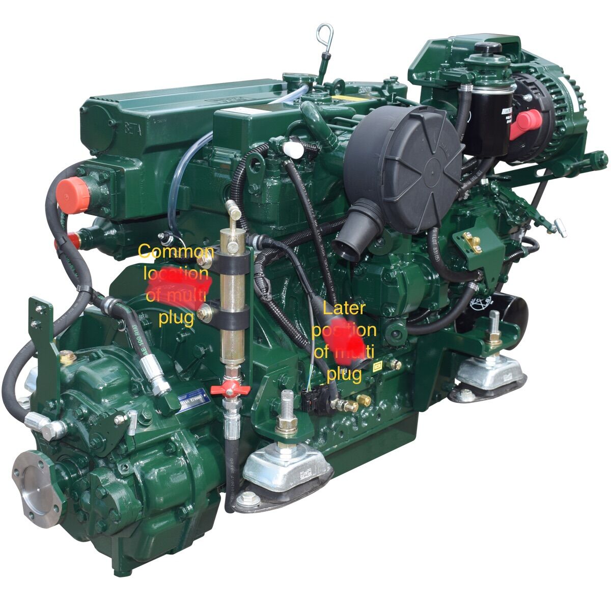
Does this help? Even the latest type can still be folded back over the bell housing to the "common" location.
-
https://www.arc-components.com/automotive-key-switches.html Fourth one down, centre column; if you need one. It has a common key, so if you want a unique key you'll have to use one of the five position ones near the bottom of the page; just ignore the extra terminals. The five position one is also used on Vetus panels where you turn the key anti clockwise to stop the engine.
-
Railway bridge repairs under way to link Gloucestershire canals
Eeyore replied to Alan de Enfield's topic in General Boating
Pity the BBC couldn't manage a picture of the existing culvert under the embankment!! -
This post cannot be displayed because it is in a forum which requires at least 10 posts to view.
-
I seem to recall that the rather complicated crankcase cover joint has some involvement in crankcase vacuum on the LPW/LPWS engines. A failed/poorly fitted gasket can raise crankcase pressure.
-
Has one of theirs on the last boat https://edwardianbedding.co.uk/narrowboat-mattresses/ Made to measure with a wide choice of internal construction.
-
A couple of weeks ago the brokerage phoned me about the survey the, then, prospective purchaser had payed for. All was as expected until they read the part about the large rust hole where the cabin side met the gunnel, estimated at £500 to repair. It was the drain from the former gas locker, now used for general storage, and still needing a drain.
-
This post cannot be displayed because it is in a forum which requires at least 10 posts to view.
-
This post cannot be displayed because it is in a forum which requires at least 10 posts to view.
-
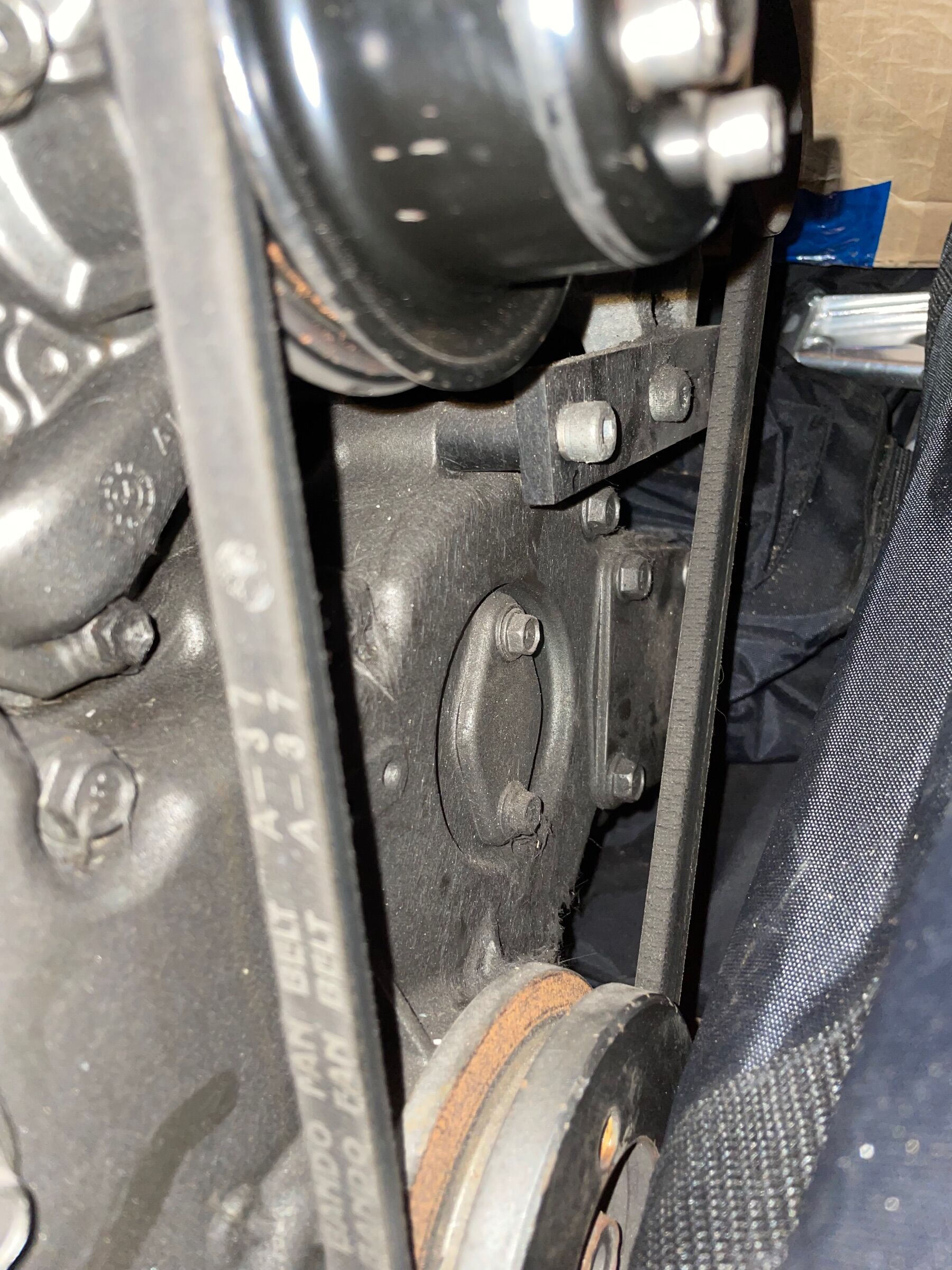
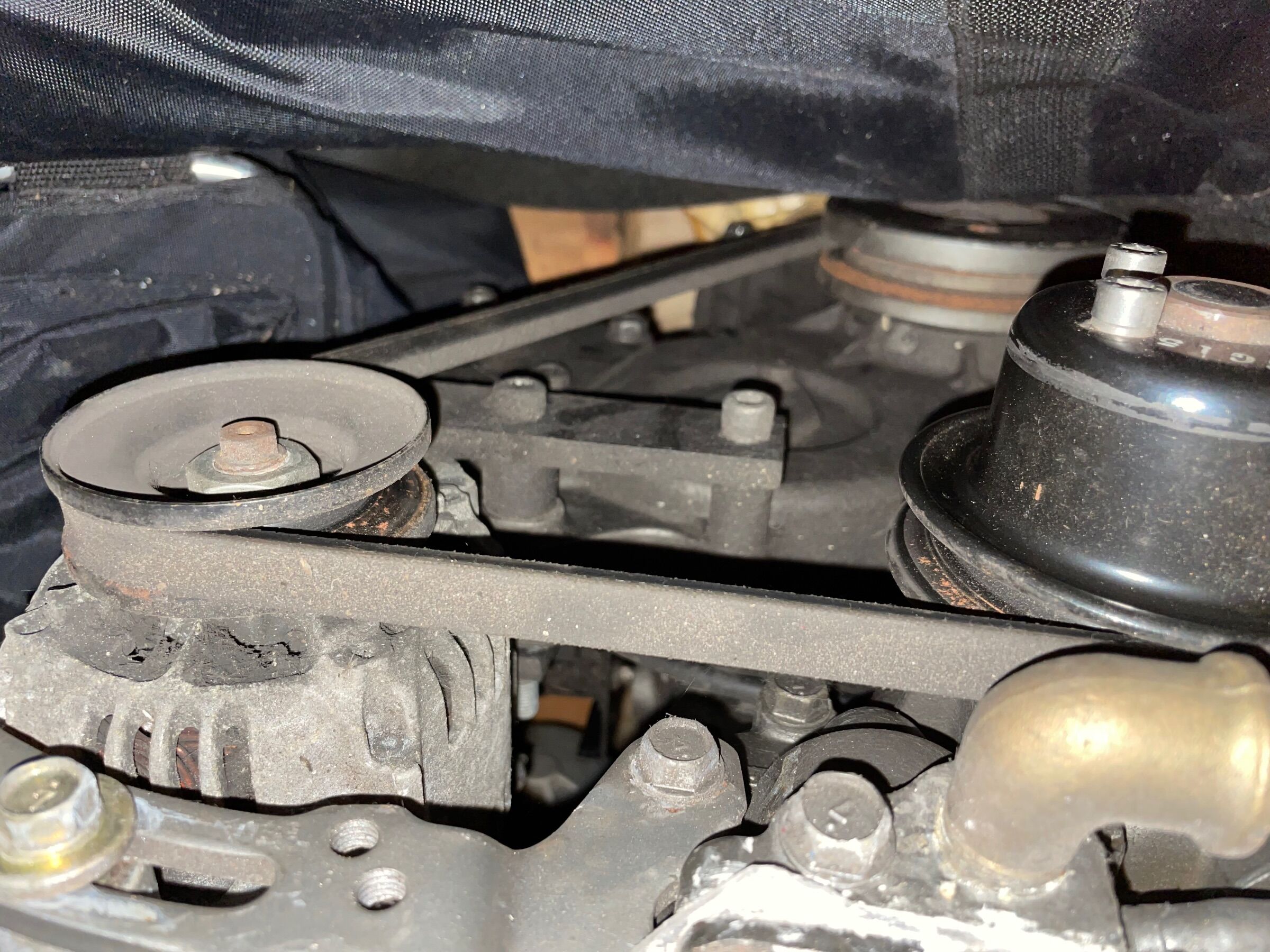
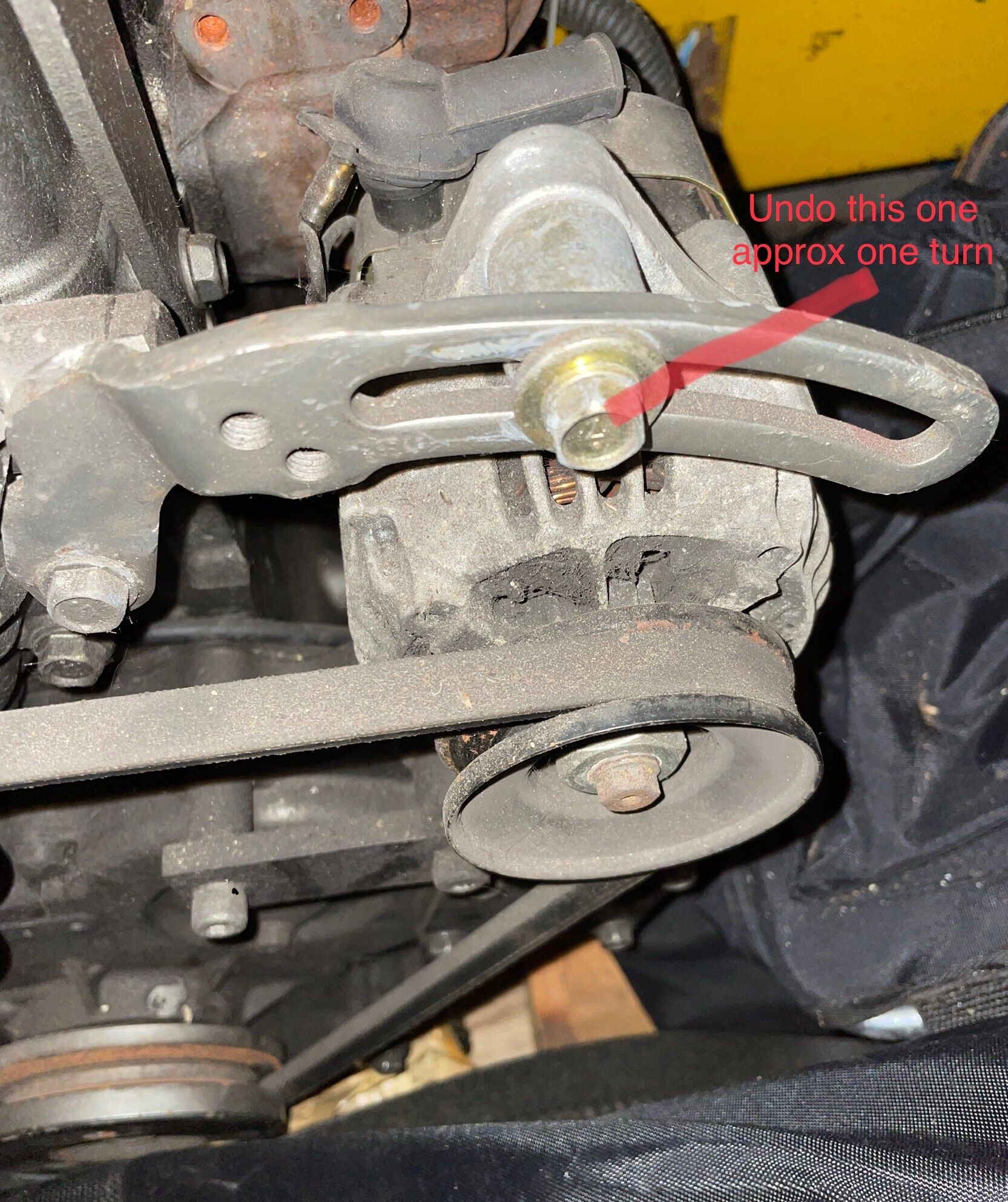
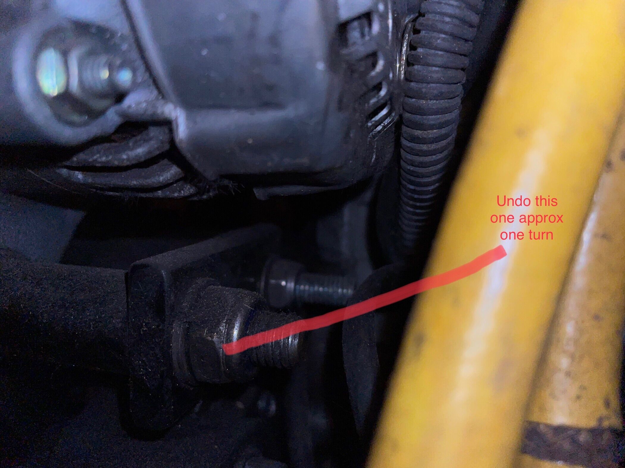
I'll have to post the photos individually. Slacken where indicated and swing the alternator towards the engine to remove the belt. You will need to remove the other belt for access; similar arrangement, except that you might need two spanner's for the pivot bolt.
-
I have a Barrus 35 in the garage. I’ll get some photos later for you. It only has what you describe as the “upper belt” which goes around 3 pulleys (crank, water pump and alternator.). You will need to remove the “lower belt” as its in the way.
-
Thanks for all your replies, some interesting technical stuff for me to absorb.
-
Ahh, the joys of leaving your boat in the care of others. I'm strangely drawn to number 3 😏
-
I have a typical Vanette oven and hob installation as the only gas appliances on my 1996 boat. The gas locker was relocated about six years ago and all new pipework and fittings installed. Tested at install and on two subsequent Boat Safety examinations. The boat was dropped off at the brokerage mooring and, for the first time since the installation, the valve on the gas bottle was turned to the off position. There was certainly no smell of gas on the boat when I lifted the cabin bilge hatch as part of the pre sale tidy up. A month latter the surveyor opened the bottle valve, performed the leakage test, and pronounced that the oven was leaking. I guess I really am a lucky B*****d, but what could have failed simply as a result of isolating and then de isolating the supply?
-
3 cyl 1100cc diesel? Just put a additional split charge relay between the generators battery charging alternator and the domestic bank and run it in parallel with the existing mains charger. That will speed up the bulk phase a bit without excessive expenditure.
-
Engine alternator issues.....any suggestions?
Eeyore replied to Wanderer Vagabond's topic in Boat Building & Maintenance
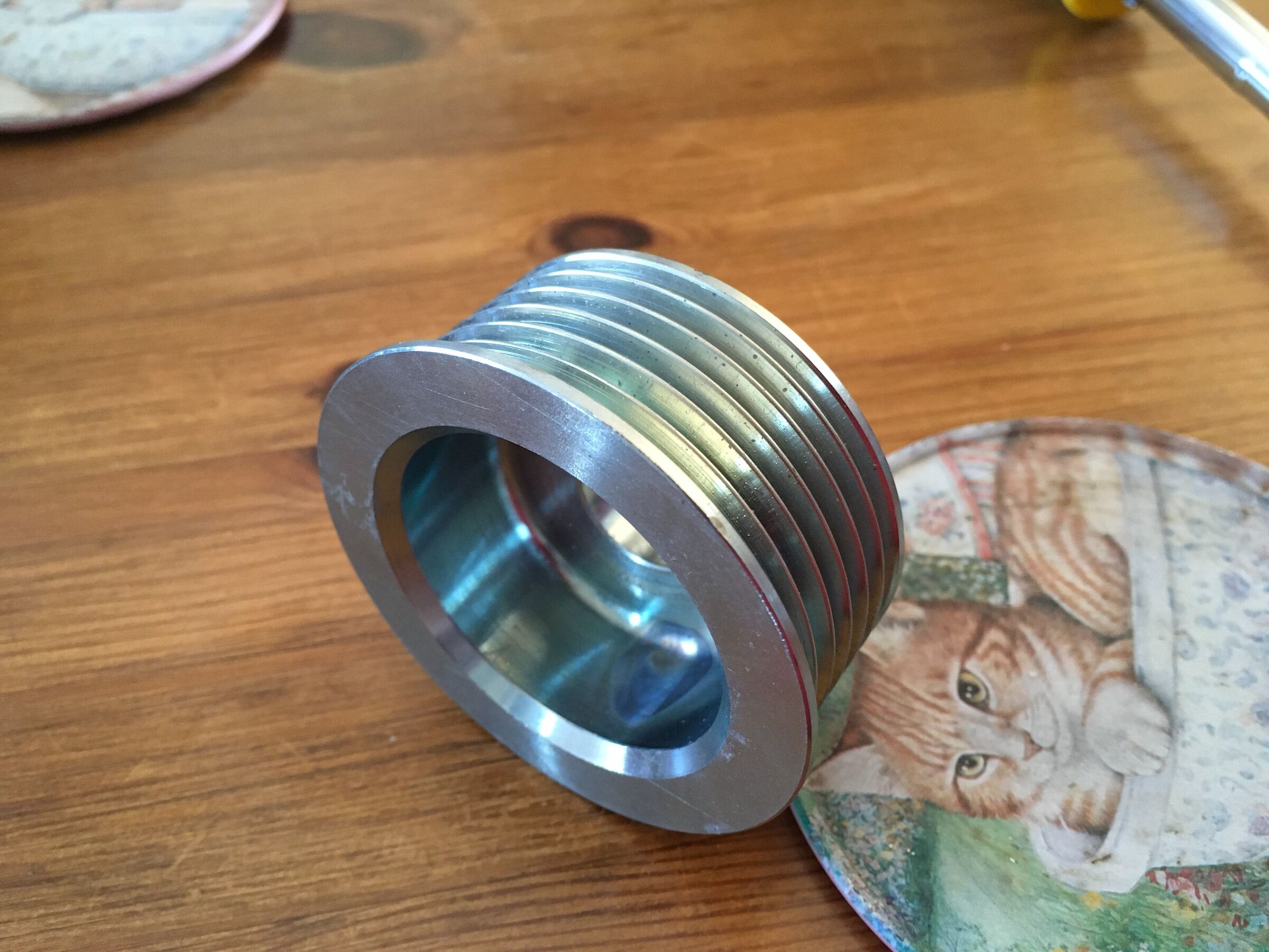
Is this one any use to you, it's 55mm dia. Located in Great Haywood.
-
Engine alternator issues.....any suggestions?
Eeyore replied to Wanderer Vagabond's topic in Boat Building & Maintenance
I think about 10mm bigger, it was a while ago. -
Engine alternator issues.....any suggestions?
Eeyore replied to Wanderer Vagabond's topic in Boat Building & Maintenance
Been there, done that. Had the same thing on an LPW3 in our previous boat. After much faffing about I concluded that the 4PK belt in combination with a small alternator pulley just didn’t play nicely together for a short while after start up due to the high demand on the alternator. The solution was to fit a slightly larger pulley to the alternator to increase the “wrap” and thereby increase the contact area between the belt and pulley. -
37 variants to choose from. https://www.prestolite-eu.com/pc/alternators/avi128/
-
And of course if it leaks you must (as most on here already know) NEVER use any metallic tool to remove the old seal; you'll damage the bore and it will leak forever. Remove the nut to remove the lever; be ready to catch the spring and ball. Hold a cloth over the hole and crank the engine over to allow the oil pressure to expel the seal.
-
Beta Marine 28 starter motor removal problems
Eeyore replied to Karen Lea Rainey's topic in Boat Building & Maintenance
Just to be optimistic, it could be a drive plate mounting bolt has come out of the flywheel. -
What have you fettled for the boat today?
Eeyore replied to Captain Fizz's topic in Boat Building & Maintenance
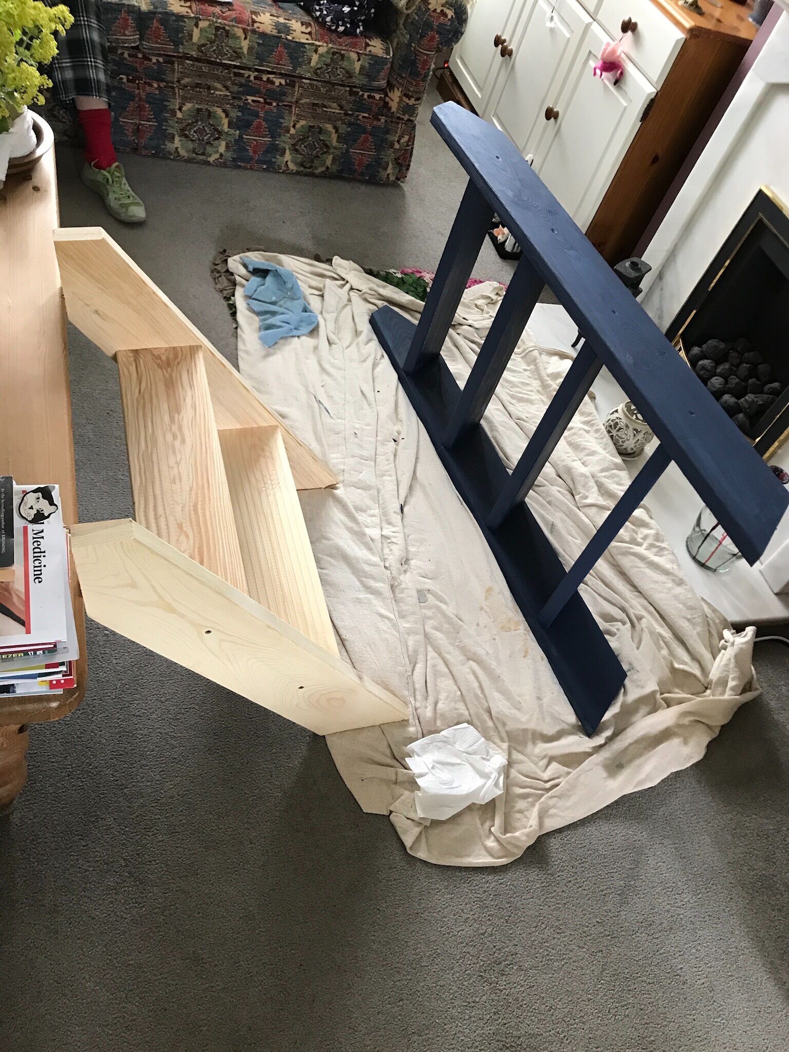
New steps for the little project boat. Being a lazy person I cut these out of a 57 degree loft stair kit 🪚
-
Bad Vibrations (from an alternator)
Eeyore replied to spicemouse's topic in Boat Building & Maintenance
I wondered why the engine itself wasn't moving about very much in your video; looks like the broken bracket is resting (wedged) on the timber bearers. There isn't a lot of space, and I wonder if the engine had been hitting the timber before the bracket broke? When repaired I would expect to see that part of the bracket going up at 45 deg to be much deeper, such that very little of the oil filter would be visible in the "after" image. -
Bad Vibrations (from an alternator)
Eeyore replied to spicemouse's topic in Boat Building & Maintenance
Here's something to read http://www.randdmarine.com/downloads/RandD_Engine.pdf The dry weight of the engine is about 180kg, so about 200kg with alternator, oil, coolant and other items added by Beta. Take the opportunity to estimate the centre of gravity of the assembly whilst you have the jack under it. The rough position for the centre of gravity of the engine alone is somewhere in the area of number three cylinder; so a lot closer to the flywheel housing with the hydraulics hanging off the back. Extending the engine mounting beam, as David Mack says, can only help; but I doubt you get sufficient length to achieve perfect balance. -
Bad Vibrations (from an alternator)
Eeyore replied to spicemouse's topic in Boat Building & Maintenance
Looks like the "best" way it could fail; loose bolts could have given a much bigger headache. There are things in your photo that say this is not the first time that it's failed; no paint on the washers and what looks like a strengthening plate ( obscured by the dipstick tube). You'll need to remove the top nuts from the new engine mounts and jack it up in order to get the engine mounting beam out. The alternator mounting beam can probably be left attached as long as you disconnect and remove the alternator. Make sure that the beam sits equally on the engine mounting points before you fit the bolts otherwise the whole thing will twist as you tighten the bolts, which is very likely to have be a contributing factor in the failure.