Rincewind
-
Posts
109 -
Joined
-
Last visited
Content Type
Profiles
Forums
Events
Gallery
Blogs
Store
Everything posted by Rincewind
-
On the other side of the canal behind where you took that photo, I used to moor my boat when it was first launched, ( there was a boatyard there below the dry dock - boatyard now long gone). My boat was broken into - through the window, and the replacement window - twice within two weeks! nough said! Do not go there!! It massively influenced my decision to move further south, never had any problem - so far - since. 🙂 We, myself and a few other boat owners, staked out out the site overnight for several nights in an attempt to catch the b*****d and we nearly did. We called the police when we saw him return at around two in the morning only for the police en-route to the scene to F**k it it up by ringing our mobile, the unexpected ring tone that alerted him that something was amiss. He legged it. Don't think the chief constable was too happy about their cockup, he also owned a narrowboat moored in Wigan that had been broken into! That is such a good question! Let us see if anyone knows! Just where is/was Wigan Pier?
-
Black, Red, Brown (or Electric Blue) paint is great but that green and yellow striped paint is the devil to apply
-
Rusty, PM'd you
-
It appears to be a double row ball race with only one spacer ring, is that correct? What is the general appearance of the ball race? Shiny / rusty / discoloured? well greased? Dirty grease? does the grease feel gritty when you rub a little of it between your fingers? Not sure what is going on there but the housing felt seals do not make contact with the shaft allowing grit, water and other debris to enter the bearing. A different type of shaft seal should have been used (they are available) but installing them now would mean removing the bearing from the shaft. If that ring came from the coupling side of the bearing then there is no scope for moving the shaft backwards while it is bolted down. The only way that I can see to disengage the coupling is to slacken the four clamping bolts on the (brass?) coupling and slide it along the shaft. That would be normal anyway if the flexible coupling were to fail in normal use.
-
Could we have a few pictures of the coupling arrangement please. When you say "metal to metal sound", where exactly is the sound coming from - the stern tube bearing area or the SKF bearing? I would not expect the shaft to move backwards as it would be held in position by the SKF bearing. These are usually Spherical roller or ball race bearings mounted on a tapered sleeve on the shaft with the outer race sandwiched between two spacer rings within the bearing housing. If this is the case then removing one of the rings (the rings have a section cut out in them to allow them to be placed over the shaft after assembly), will allow the shaft to be moved back by about 6mm (or whatever the width of the ring is). Temporary replace the coupling bolts and then remove the two long bolts holding the bearing housing cap in position and remove the bearing housing cap for inspection of the arrangement and condition. The cap may need tapping with a mallet if it is stubborn. Note that the cap casting is normally "keyed" so that it mates with the base one way only. Post a picture of what you see inside.
-
You are on the right track! SKF bearing housings usually have elongated mounting holes to allow some adjustment. Shims - It is unlikely that you will need any shims IF – (and that’s a big IF 😀) the shaft was originally aligned correctly and that the shims, if any, have not turned to rust! If the shims (if fitted) are ok and the above is true, then theoretically, the shaft cannot move in a vertical plane unless the SKF bearing has collapsed. Before you do anything else, clean the components and surrounding areas with a wire brush. (1) With a sharp scriber or nail, scribe a line around the bearing housing base onto the bearer. (2) When the shaft is cleaned use a permanent marker pen to mark a wide band around the shaft at the mouth of the stuffing box. Place a steel ruler against the face of the stuffing box and where it touches the shaft; scribe a line on and around the shaft. You now have reference points to return to should anything move unexpectedly. The line on the shaft will record the position (distance) of the propeller relative to the hull as it is now. While the boat is out of the water you could measure the distance between propeller hub and the hull and make a note of that for secondary reference as well. Prior to re-aligning the prop shaft, remove all the old packing. That, I have to say, can only be ascertained by close examination of the bearing and engine mounts. When you come to repack the gland:- Assuming that you have bought a length of packing and not "ready cut rings" wrap the packing around the shaft and with a sharp knife, cut the loose packing end at 45 degrees (looking down from above onto the shaft) and then cut a turn of packing at 45 degrees so that the ends overlap and mate with each other forming a ring with no bulge or gap. - A fair amount of precision is required here. This will ensure that no "short cut gap" will be introduced to the gland which otherwise could be the case if the ends were cut straight. (I.e. cut short at one end 😁) Install the first ring with the ends at the 12 o'clock position, the second ring with the ends at the 4 o'clock position and the third ring with the ends at the 8 o'clock position. Push each turn into the gland with the gland follower to keep them square and finally tighten the gland follower retaining nuts finger tight with an extra half turn with a spanner. Use two nuts on each stud locking them together. The final adjustment will be when the boat is in the water.
-
If you use Dynmo or other kind of print label attached to your chosen object then if it is appropriate, over lay it with transparent heatshrink tubing. It still wont stop it from being mislaid or stolen though 😁
-
Thanks for the reply. That seems to confirm that the shaft is out of line and that the bore of the gland follower is now oval due to being worn away by the shaft. Do not worry too much about the ovality of the gland follower, it is not a big deal and it can be reused again. But you do need to re-align your prop shaft etc. Where is the boat ashore at the moment? I may be able to offer some help if you wish and your not too far away.
-
And thereby lies the problem, i.e. boat builders / installers and to a lesser extent, owners using the stuffing box / gland as a convenient bearing, which it is not and was never designed to be. The stuffing box is screwed onto the stern tube to enable the two components to be concentric with one another. In the OP's case, (we are led to believe), another bearing - an SKF - has been fitted to the shaft (on a bearer we hope & presume 😁) some distance away from the gland in order to align the front of the shaft with the stern tube bearing. This arrangement is good engineering practice as, with the shaft now suspended between two bearings it leaves the stuffing box gland assembly to do what it was solely designed to do - namely - to create a Dam and a cooling jacket around the shaft. (a small amount of water will penetrate the weave of the packing creating a mini reservoir and help it remain supple). From the evidence we have it would seem (but not conclusive) that the engine/gearbox has become mis-aligned and forced the SKF bearing to one side together with the shaft thereby accounting for the discrepancy in the OP's measurements. My Capitals & BOLD! Which is why I asked the OP if the gland follower would fit into the stuffing box 180 degrees about. As we cannot examine the gland follower for ovality ourselves and should it transpire that indeed it does not fit when turned 180 degrees, it would be another indication of misalignment.
-
Thats true in most circumstances but the OP said there was another bearing, an SKF type on the shaft at some point but not shown in the pictures and the stuffing box assembly is usually screwed onto the stern tube.
-
As the packing thickness is 8mm, it follows then that there is a gap between shaft and packing on one side which is why your gland is leaking excessive water. No amount of renewing, tightening/squashing the packing will alter that fact. It may cover it up temporary, but - Ostriches and sand mentality would then apply here. Ideally, as Tracy suggests, it would be better if the shaft was aligned so that it is concentric with the internal diameter of the gland, which means decoupling the prop shaft from the drive while this is carried out. And then, and only then, align the engine/gearbox to the propeller shaft. But from what I have gleaned so far from this thread, I suspect starting this task would open a whole can of worms and the resulting total cost in monetary terms may exceed the cost of a few turns of packing. An Ideal time to sort it out though, while the boat is high and dry. For reference, the gland packing is designed to not only (A) Create a Dam to hold back the bulk of the water that migrates through the propshaft bearing but also (B) Act as a reservoir of water in order to dissipate heat created by the friction between the shaft and the surface of the packing when the shaft is rotating. It is not designed to act as a bearing, which, from this scenario, it appears it is! (And putting undue load on the packing at one side compounding the issue!) Be aware, this type of gland is designed to drip water during normal running. Not only do the drips carry away excess heat, they are a visual indication that cooling is taking place and all is well. The "Rate of Drip" is controlled by judicial adjustment of the Gland Follower - (often referred to as the "pusher") and should not be tightened excessively which will damage both packing material and shaft. Just as a check, does the gland follower enter the gland (by hand) without restriction or excessive force and then if you rotate the gland follower 180 degrees does it still enter the gland without restriction or excessive force?
-
And even more of a challenge if using round headed "Allen" screws!! 😆
-
Whichever type of bolt/setscrew you decide on, to prevent the screws coming loose when the engine is running drill a small hole through each of the heads and once they are secured, wire them together in pairs. You can use galvanized wire obtained from armoured electrical cable with a drill size slightly larger and yes, "allen" type screw heads can be easily drilled if you ensure your drill bit is sharp. The wire will not affect the balance.
-
Most companies near you that specalise in lifting equipment will be able to get some of this chain for you and may well have some offcuts if you ask them. Often used for attaching to submersible pumps so that they can be lifted out for maintenance - if you know anyone in that industry! https://www.liftinggeardirect.co.uk/lifting-equipment/lifting-slings/pump-lifting-chains/grade-316-pump-lifting-chain
-
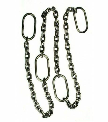
The mooring chains most frequently offered for sale in chandlers and described by the OP are, in my opinion, a pretty poor offering with the inclusion of the shackle & ring option being the result of a solution to a problem not fully thought out. A much better solution is to use a section of Stainless Steel lifting chain like in the picture below. The length of chain in the picture will make two mooring chains with the oval rings at each end able to slip through each other easily. Oval to oval is approx. 1m. I have used them for years without issue. Ditchcrawler has described the solution to prevent chains jamming between the Pilings and Waling bar but if it does jam why not use the power of the boat to release it.

-
Judging by the 'tide mark' I would say the bricks were put in there so that the previous owner could stand on them without the water overtopping his shoes!
-
If anyone has ever wondered what is inside those Poynting aerials, now you know!! Mine blew over in the wind, smashed against the roof, top cover came off and fell into the canal never to be seen again! It still works though, even in the rain !!!
-
Try looking on the outside of the boat! Assuming that it pumps water overboard there will be an discharge outlet in the hull. If you can identify where all the other outlets are connected, e.g. sink, shower etc. then the one you cannot identify may give you the approximate location of the pump. (again, assuming the discharge hose is a short one)
- 9 replies
-
- 3
-

-
- bilge
- bilge pump
- (and 3 more)
-
They already do. Sludge is incinerated at many facilities all over the country. For a short time in my working career I was employed as a Commissioning Engineer on a project in Scotland that would stop the discharge of raw sewage into the sea (an EU Directive) and divert the flow(s) into three newly built sewage treatment works along that part of the Moray coast. At Lossimouth treatment works the sludge from the three treatment plants was incinerated and the resulting ‘by-product’ (or residue) was compressed into pellets, bagged and then stored in a warehouse known as the ‘Pellet Store’. Why, you may ask? Because the pellets were then used (sold) as animal feed during the winter months! Enjoy those Scottish steaks you buy in the supermarkets everyone, they are so full of Sh.. , sorry, Scottish goodness!!
-
He often 'rambles' when he's had a drink or two
-
Hospital silencer orientation and support
Rincewind replied to TandC's topic in Boat Building & Maintenance
Same type of silencer as I have as far as inlet / outlet orientation is concerned. Looking at the illustration you have provided (end on) the "inlet" is orientated "East". It does not have to be that way inclined, (your options seem to suggest keeping the 'East or West' orientation) so consider rotating the inlet to a different "compass point" to provide more flexibility in positioning / ease of mounting of the silencer and, as Ian has pointed out regarding stiffness, it may provide more flexibility with the coupling pipe. Use of elbows or swept bends on either - or both - the engine manifold and silencer will achieve this. For what its worth, my hospital silencer is parallel to the engine alignment in order to maximise space in the engine room. Also consider where the exhaust fumes will exit the boat hull, astern is better than forward of the steerer! -
Worm drive hose clips are ok for some applications but if you require a good seal on critical joints you should consider using clamps such as these:- https://www.thehosemaster.co.uk/superclamps-stainless-steel-clamps I am not promoting this particular company to buy from, (do your own research) but with this type of clamp, all round torque and compression can be applied. They are often much wider than "Jubilee" worm drive clips and therefore just one clip of this type (referred to in the link) is often sufficient as a replacement where previously two worm drive clips have been used. They are available made from stainless steel.
-
Yes, you are most likely correct, the components they used would probably be unidentifiable after removing the resin. On my own boat I have a microprocessor that monitors the engine functions so I was just curious to see if their ideas (VDO, The Manufacturers of the unit, - a Canadian company I believe) were similar to mine! I have checked their website but can find no reference to your unit - most likely now, an obsolete product. Thanks for the photos and feedback though, much appreciated! Nice to know you are "up and running" again.
-
On the topic of informal Lido's, many years ago the St. Helens canal near the town center was such a place all year round. Pilkingtons Glass had a factory alongside the canal and they used to draw water from the canal for cooling purposes and then return it to the canal - at a much higher temperature. You could go swimming there without restriction. It was known locally as the "Hotties" and the water was, as I recall, crystal clear. (Sadly not now!) Pilkingtons raised the temperature of the canal water so much that someone put some tropical fish in that section of the canal and within a short time they had multiplied to the extent that the canal was teeming with them! They thrived for years until Pilkingtons changed their production methods and stopped using the canal water.
-
By the looks of things, from what I can see, it would seem like they have supplied you with a different (decent) ignition switch so you will most likely not need that diode on this set up. Not that it matters now, but just out of curiosity I would be interested to see the internal workings of that IR/ETR device and of the VDO alarm device and see if it matches my thoughts on how they are configured! (Don't worry about it, its just how my mind works, I am naturally curios about these things!) So don't chuck em in the bin if you decide to ditch them, let me know, as the schematic / connection diagrams you provided raises several questions. Did they supply you with a schematic / connection diagram? Good luck with your installation.