Rincewind
-
Posts
145 -
Joined
-
Last visited
Content Type
Profiles
Forums
Events
Gallery
Blogs
Store
Everything posted by Rincewind
-
Just what are you suggesting here? 🤣🤣🤣
-
Centreflex CM-160 Coupling
Rincewind replied to Unicorn Stampede's topic in Boat Building & Maintenance
Thanks for the feedback. Best of luck with the "Fix" !! -
Centreflex CM-160 Coupling
Rincewind replied to Unicorn Stampede's topic in Boat Building & Maintenance
It is not "stuck" as such!, It is locked in position on a taper! Look at the flange where you have removed the "eight bolts - or setscrews". there are two (or more) threaded holes inbetween the clearance holes. Insert two of the setscews you have removed from the flange and tighten them each little by little and the coupling will be jacked off the shaft taperlock. Once the coupling is released, if the tapered piece is still stubborn to move on the shaft, gently and carefully drive a thin wedge into the "split" in the taperlock and it will slide along the shaft. Dont overdo it with the wedge and proof mark the position of the tapered sleeve before disassembly. During reassembly the 8 setscrews should be tightened progressivly until the coupling is locked in position. -
Could have been a typo, Perhaps he meant MESS 😲
-
The obolong indents you refer to have been introduced by the manufacturer to provide rigidity to the pressed sheet steel in order to help prevent the entire mating surface from deforming whilst in use and assembly. Once you have cleaned the mating surface(s), you could check for uniform flatness by placing the sump on a flat surface (e.g. a sheet of glass) and visually check for any deformity between the two surfaces. If all is satisfactory then assembly with the gasket and a suitable sealing compound is all that is required. Tighten the screws evenly and to the recommended torque recorded in the manual.
-
(Slightly off topic so appologies to the OP.) If I recall corectly it was called Stag jointing paste (?) and was loaded with lead, hence the need to stir the tin contents before use! Often used with plumbers hemp to fill the voids in the crudely cut threads!! (Pre PTFE days) It was pretty good on steam and hot water pipes as it set like rock - and all over your fingers! Oh Happy days!!!😁 It is still available but no lead additive these days, so do not know if the revamped ingredients are as effective as the pre H&S compounds used to be!!
-
Diesel heating fuel feed from main tank
Rincewind replied to TugFan's topic in Boat Building & Maintenance
With a stepped cone cutter, enlarging the hole step by step will invariably allow swarf to pass into the tank as there is no control over swarf movement. If using a hole saw however, swarf will be discharged outside of the tank until the moment the cutter breaks through with minimal discharge into the tank. The disc of metal produced by using a hole saw also reduces the amount of swarf generated and even if the disc falls into the tank (unlikely), it will pose no problem compared to excessive amounts of swarf from the stepped cone cutter method. In order to minimise swarf from passing through the pilot hole whilst drilling, fill the hole saw with grease that will capture and retain the swarf. Fill the flutes of the pilot drill with grease also for the same reason. Clean the swarf from the pilot drill flutes once the pilot hole has been established and refill the flutes with grease. Alternatively, once the pilot hole has been cut, change the pilot drill for a solid steel rod of the same diameter. The grease may provide some lubrication to the cutter (and pilot rod if used) but the use of a proprietary cutting fluid liberally applied will aid and maintain a sharp cutting edge to the hole cutter. As to cleaning the tank, that is up for debate! ☺️ -
What drill bits to drill through steel?
Rincewind replied to Alway Swilby's topic in Boat Building & Maintenance
For machining Steel, use an oil based cutting fluid. For machining Cast Iron, machine it Dry, the high carbon content of the cast iron acts as a lubricant. For deep holes use compressed air to remove the swarf and cool the cutter. For Machining Brass, machine it Dry. (By reducing the rake angle of the drill to zero - i.e. the correct rake angle for Brass - will prevent the drill fom "snatching" as it breaks through. Most if not all drills are supplied with the rake angle set for cutting steel. For machining Aluminium, a thin oil like parrafin is recommended. -
Prop shaft wrapped in cable ties.... ?
Rincewind replied to bigoltubosteel's topic in New to Boating?
You may well think this and you are entitled to your opinion, however your opinion is precisly that - an opinion. On the other hand my explanation as well as the contribution from Tony is based on over 40 years experience in Engineering maintenance. If you still do not believe us I suggest that you log on to the manufacturers website and read how to assemble and fit this type of bearing. Please lodge your complaint with the manufacturer. -
Prop shaft wrapped in cable ties.... ?
Rincewind replied to bigoltubosteel's topic in New to Boating?
The same applies, It does not matter as there will be movement of the needle rollers in either scenario. -
Prop shaft wrapped in cable ties.... ?
Rincewind replied to bigoltubosteel's topic in New to Boating?
If the cardan shaft is indeed offset between the prop shaft and the power unit then that part of the drive shaft is correctly fitted. Cardan shafts should not be aligned perfectly straight as that would inhibit the movement of the needle rollers within the bearing joint, leading to premature failure. -
Seems a bit expensive! Look Here:- https://www.amazon.co.uk/Jabsco-31395-2512-3A-ParMax-3-Pump/dp/B08TJ2GNMT/ref=asc_df_B08TJ2GNMT/?tag=googshopuk-21&linkCode=df0&hvadid=697183278645&hvpos=&hvnetw=g&hvrand=9856487878942242126&hvpone=&hvptwo=&hvqmt=&hvdev=c&hvdvcmdl=&hvlocint=&hvlocphy=1006648&hvtargid=pla-1391444613807&psc=1&mcid=091ae9f36a3f3f5b8b860899f97e1886&gad_source=1
-
You could use a metal wedge. They can be bought from ironmongers, usually used for fixing hammer shafts.
-
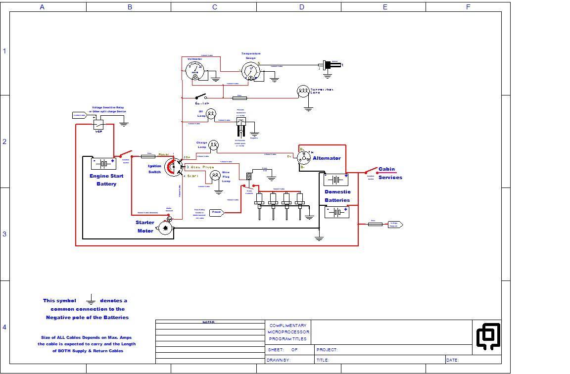
That's true, but generally speaking the convention is, (in PCB schematics) that inputs to devices or circuits are on the left of the schematic and you work from left to right with the output on the right of the circuit, although it does not always work out that way due to the complexity of the design. Incidentally, you can drag component symbols and wires around in DSPCB and they will remain attached though you may have to adjust the routing. Alternatively you can disconnect a component from the wires (nets) leaving the wires wherever you have drawn them. Input & output nodes like the ones on the "Power" to the Glow plug relay and the Bilge Pump connection help to alleviate bunching of components and the sometimes confusing crossed wires or nets.
-
Try DesignSpark PCB (DSPCB Explorer is a free version). You will need to register with RS Components in order to use the software. (free, once only registration when the software is initially launched). https://www.rs-online.com/designspark/pcb-software It is intended primary for PCB designs as the name indicates but can be used just as easily for general wiring diagrams. Designed for Windows (and Linux, via Wine I believe, although I have not tried the software on the Linux platform). You can generate / draw your own symbols within the software and save them to the inbuilt library for future use, add text on the sheet for further explanation if necessary, insert / delete / change or drag and place components at will and re-name and colour wires to make the schematic easier to follow if you so wish. Print to paper or PDF. Etc, etc. For what its worth, I prefer DSPCB for drawing general wiring schematics and DipTrace for PCB Designs. ( https://diptrace.com/ ) Thousands of free symbols to download and add to the libraries for both DSPCB and DipTrace are available online. e.g. Snap EDA, Library_Loader, SamacSys, Ultra Librarian, etc. Example below- Not Definitive, errors may be present:-

-
This post cannot be displayed because it is in a forum which requires at least 10 posts to view.
-
This post cannot be displayed because it is in a forum which requires at least 10 posts to view.
-
Dangerous towpaths, attempted assaults, have a gander..
Rincewind replied to matty40s's topic in General Boating
How did it taste? -
You need to go to Specsavers!! 😁
-
You have a choice of models, Take your pick https://www.victronenergy.com/display-and-panels See my reply to Blackrose
-
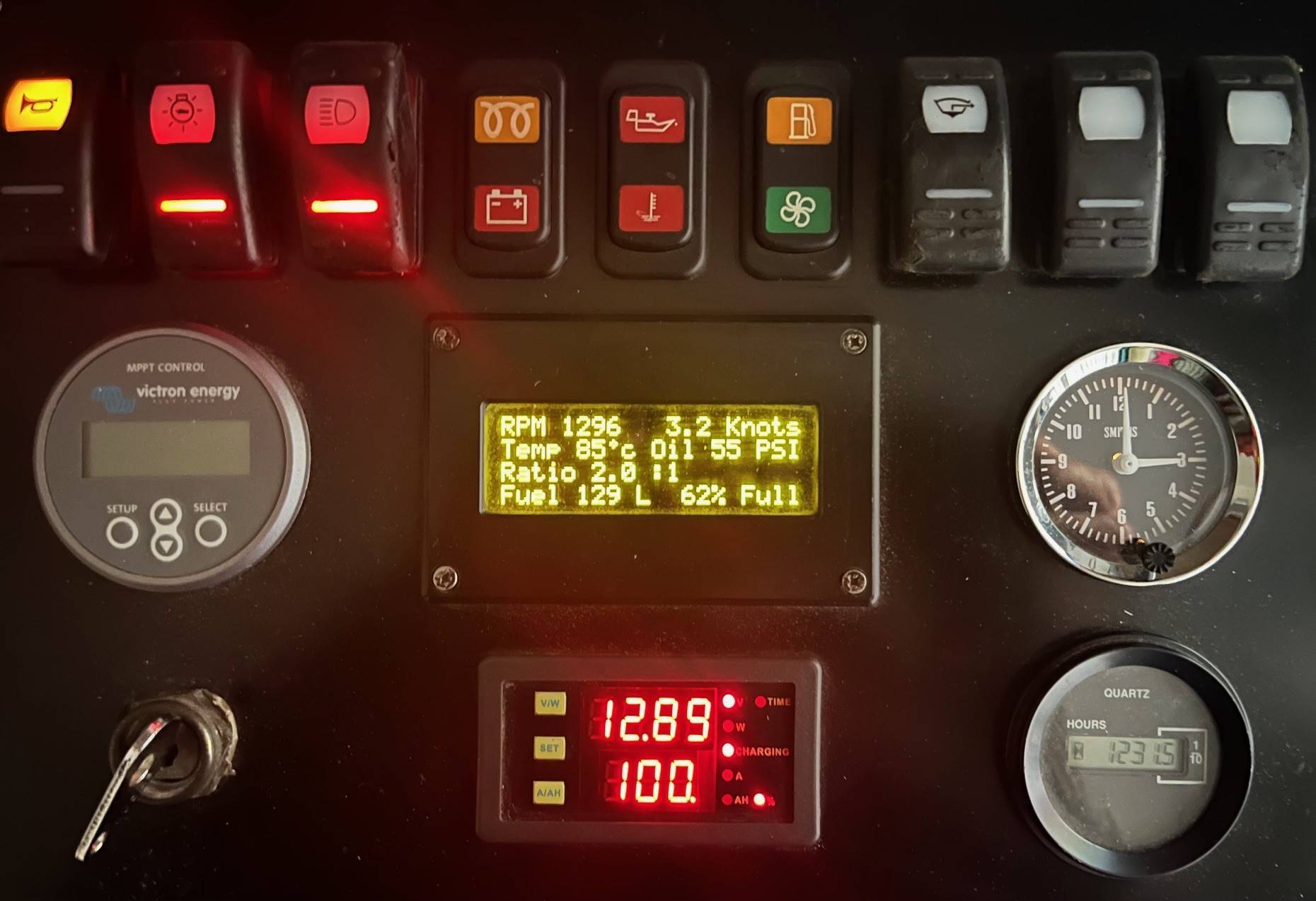
For me it was a no-brainer, like yourself, having to drag your phone out of your pocket, find the app and then retrieve the information was too much of a faff, and if the phone battery died, you were stuffed. My unit fits into a standard 50mm hole for instruments, is permantly connected and you can scroll through all the parameters with a single button (repeatable) press. The display is easy to read with a Liquid Crystal Display rather than an LCD so can be viewed in bright sunshine - when we have any! 😁 Auto off for the display and is woken up with a press of a button. Contains all the info that I need, depends on how far you want to drill down into the app or if you want to see the info from afar Mine is mounted in my control panel so that I can view it as I steer. (the panel is just inside the boat under cover so I can view it when moored up and the doors are closed)
-
That is not how it works. Rather than write a whole blog about it, you should slip the thermostat into a bowl or glass of hot water i.e. above 85 degrees C and observe what happens around the large flange. (the anvil of your vernier gauge rests upon the flange)
-
You can get arrested for that
-
It wont cure the lack of fuel delivery problem - but it would start better if you replaced the fourth glow plug!!! 😁😁😁
-
Propeller shaft flexible coupling 'broken? ?
Rincewind replied to moiuk's topic in Boat Building & Maintenance
A file 😄