pt2583
-
Posts
47 -
Joined
-
Last visited
pt2583's Achievements
")
Engager (3/12)
3
Reputation
-
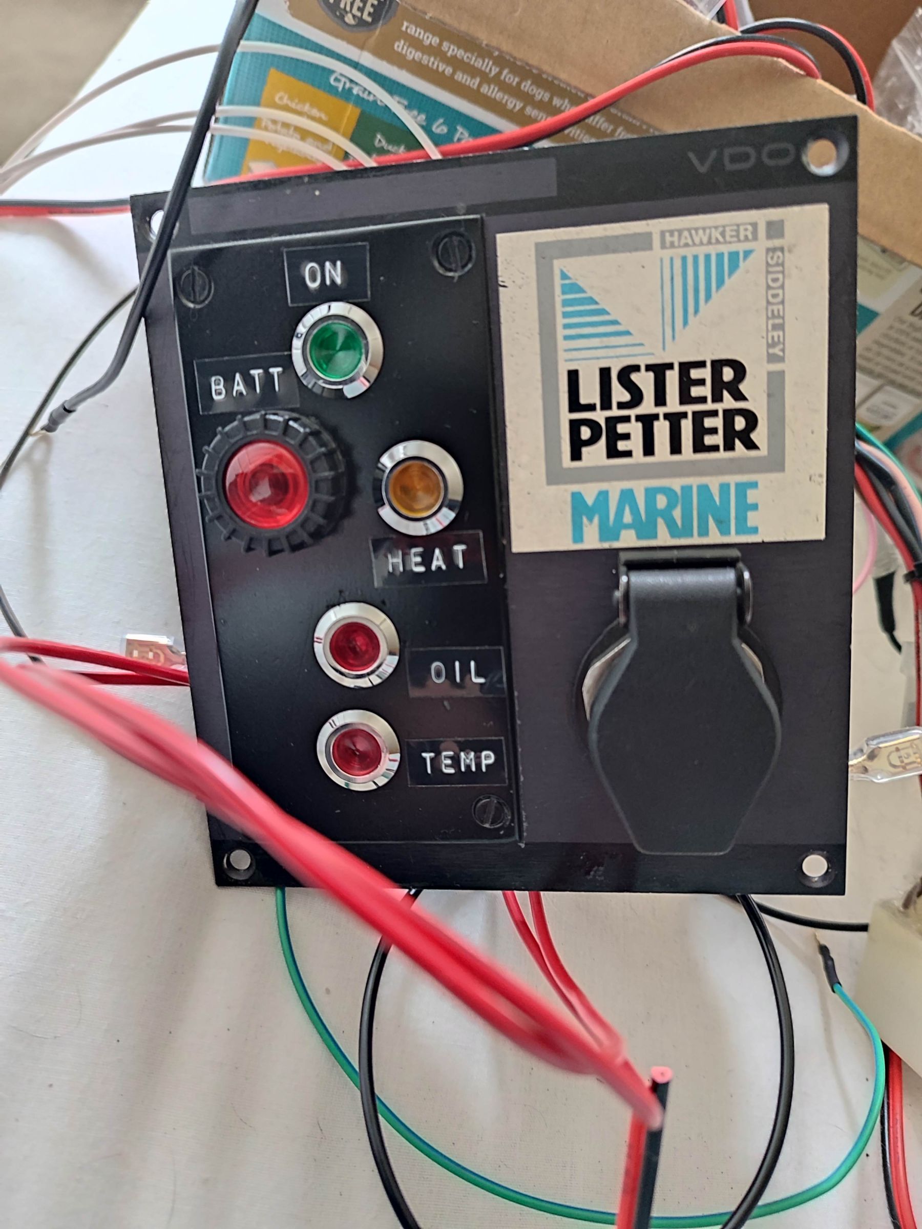
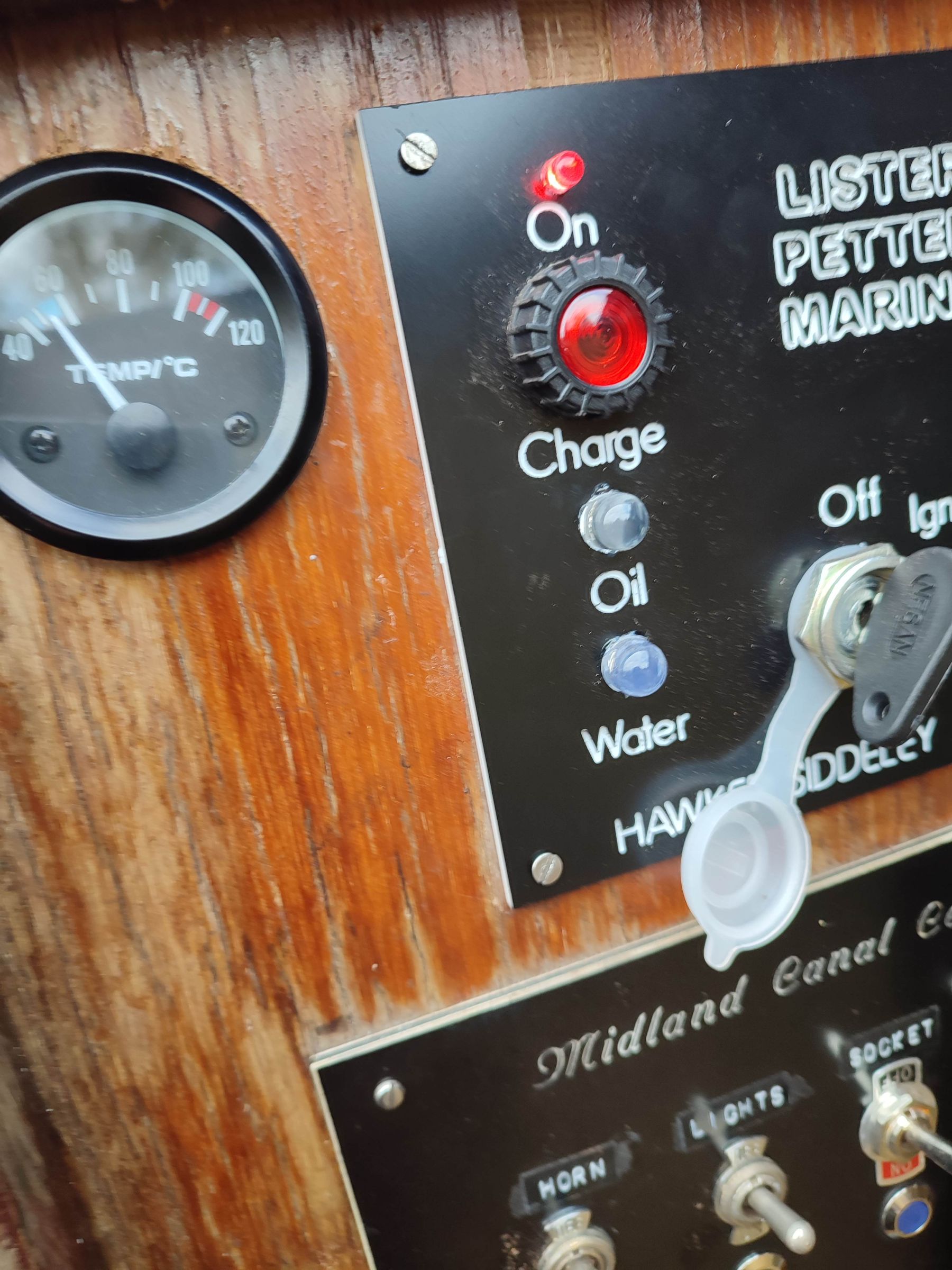
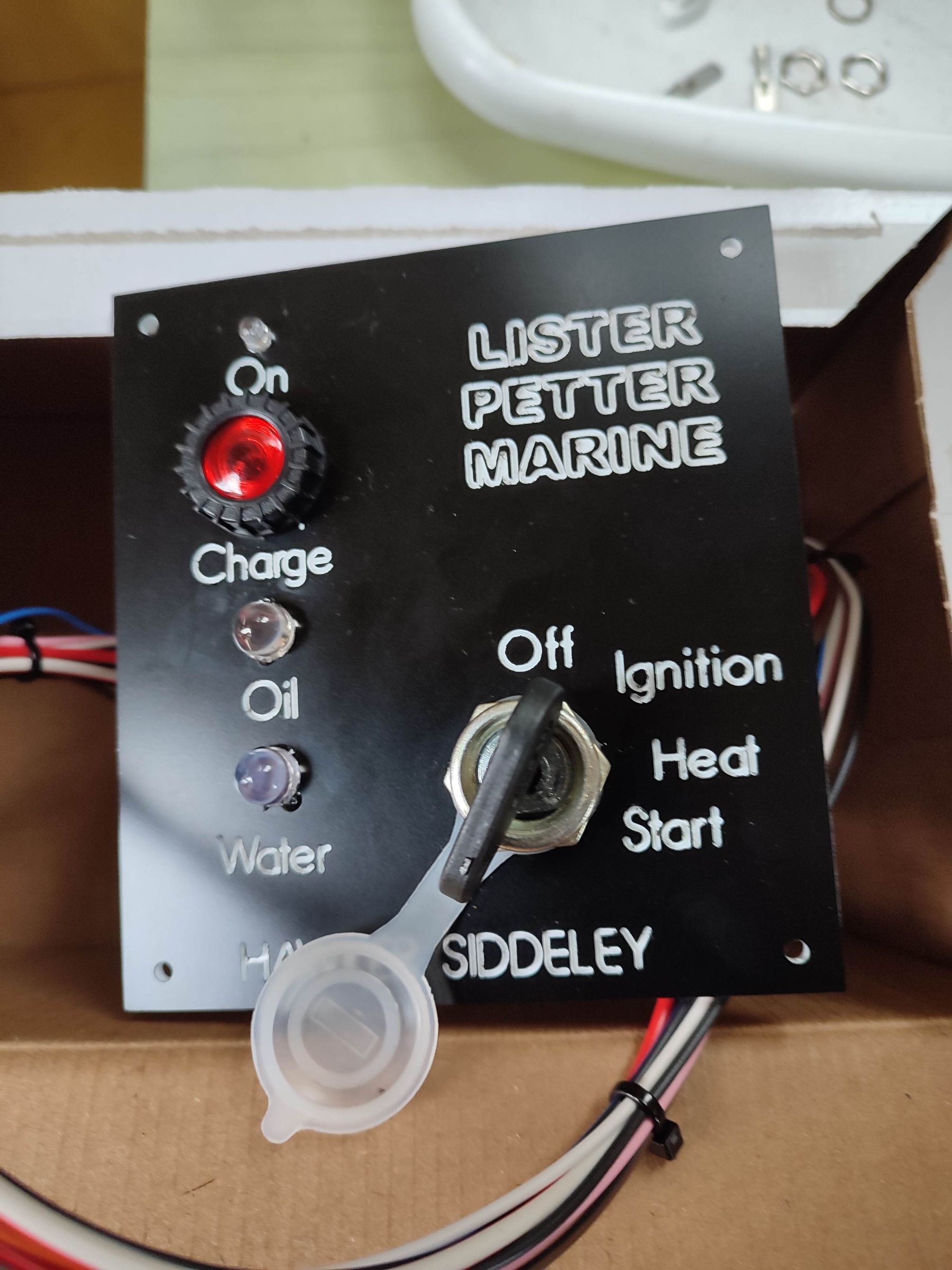
Final update. I found that upgrading the bulb in the charge/battery cct from a 2w to 3w made a significant change to the alternator excite behaviour. It now only needs a little blip of the throttle and the light goes out. So problem finally solved. I have now also finished the changes to the original instrument panel. Instead of a buzzer on the glow plug heat cct, I added an orange led light. So now have a spare instrument panel

-
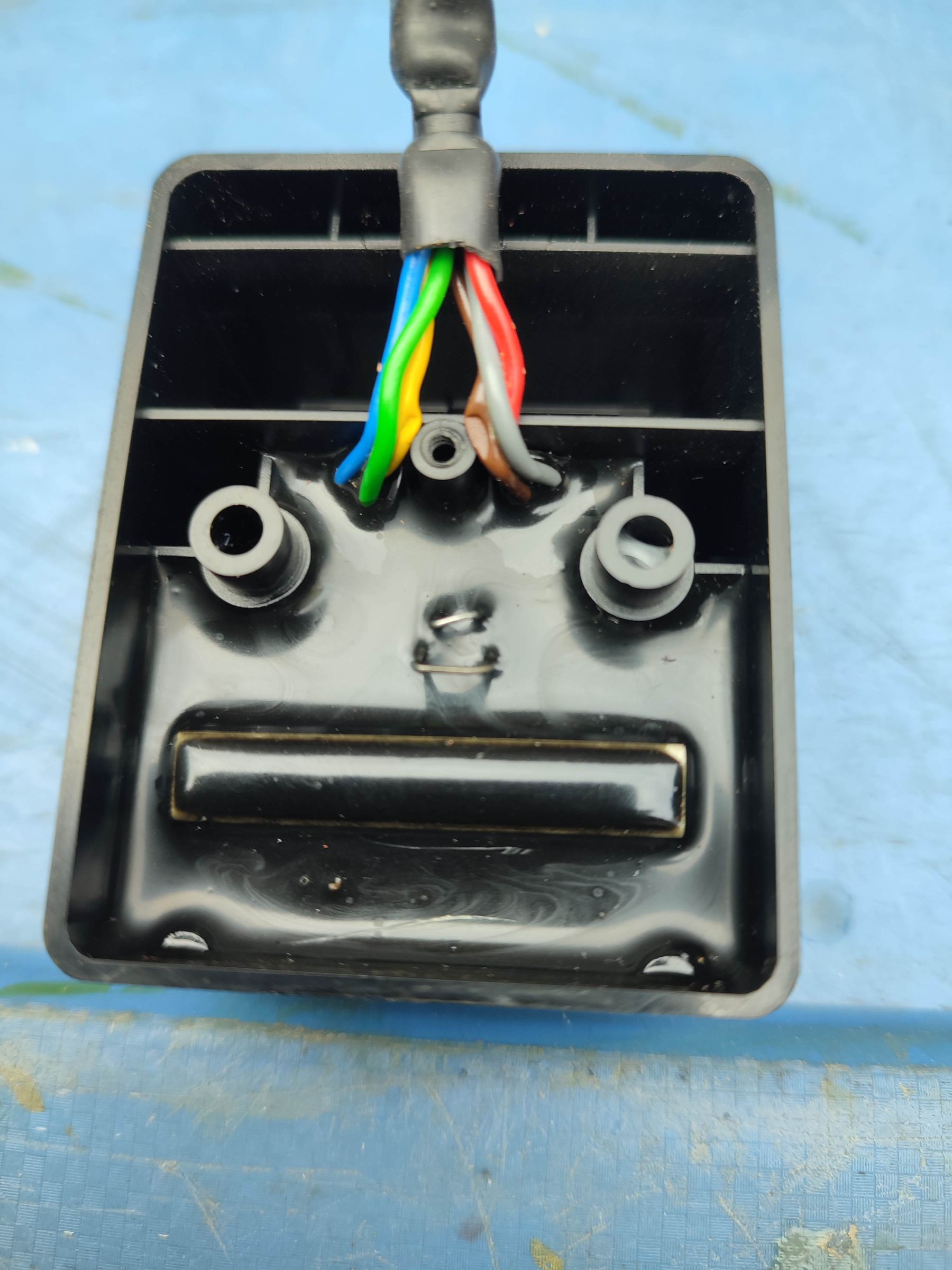
This is internal of the alarm unit. All sealed with epoxy resin. Doubt you could get it apart without destroying it That's very handy to know, been trying to figure out which one it was. They seem to be pretty cheap
-
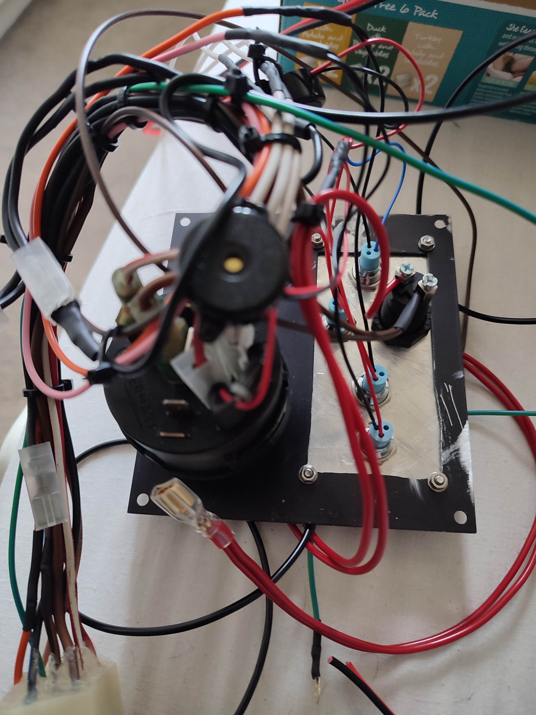
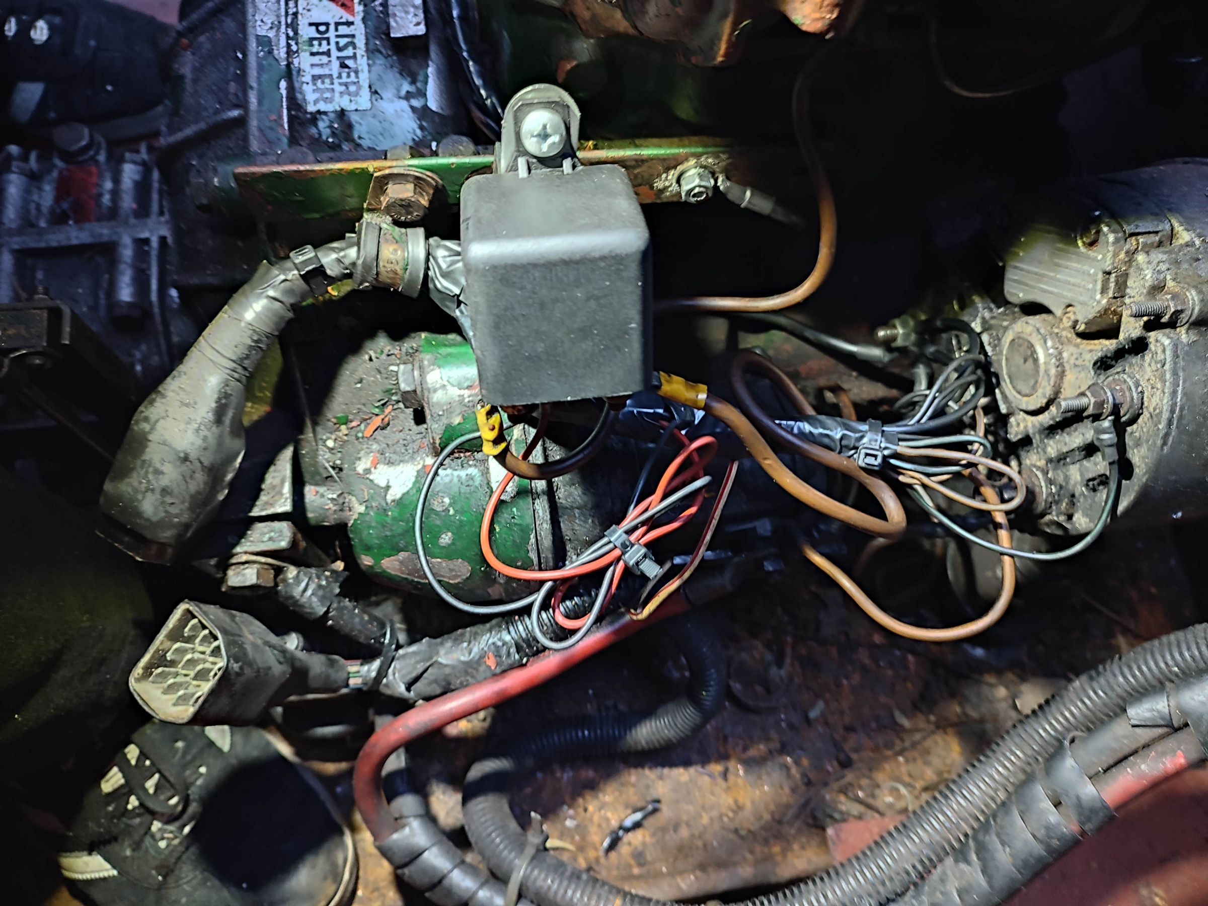
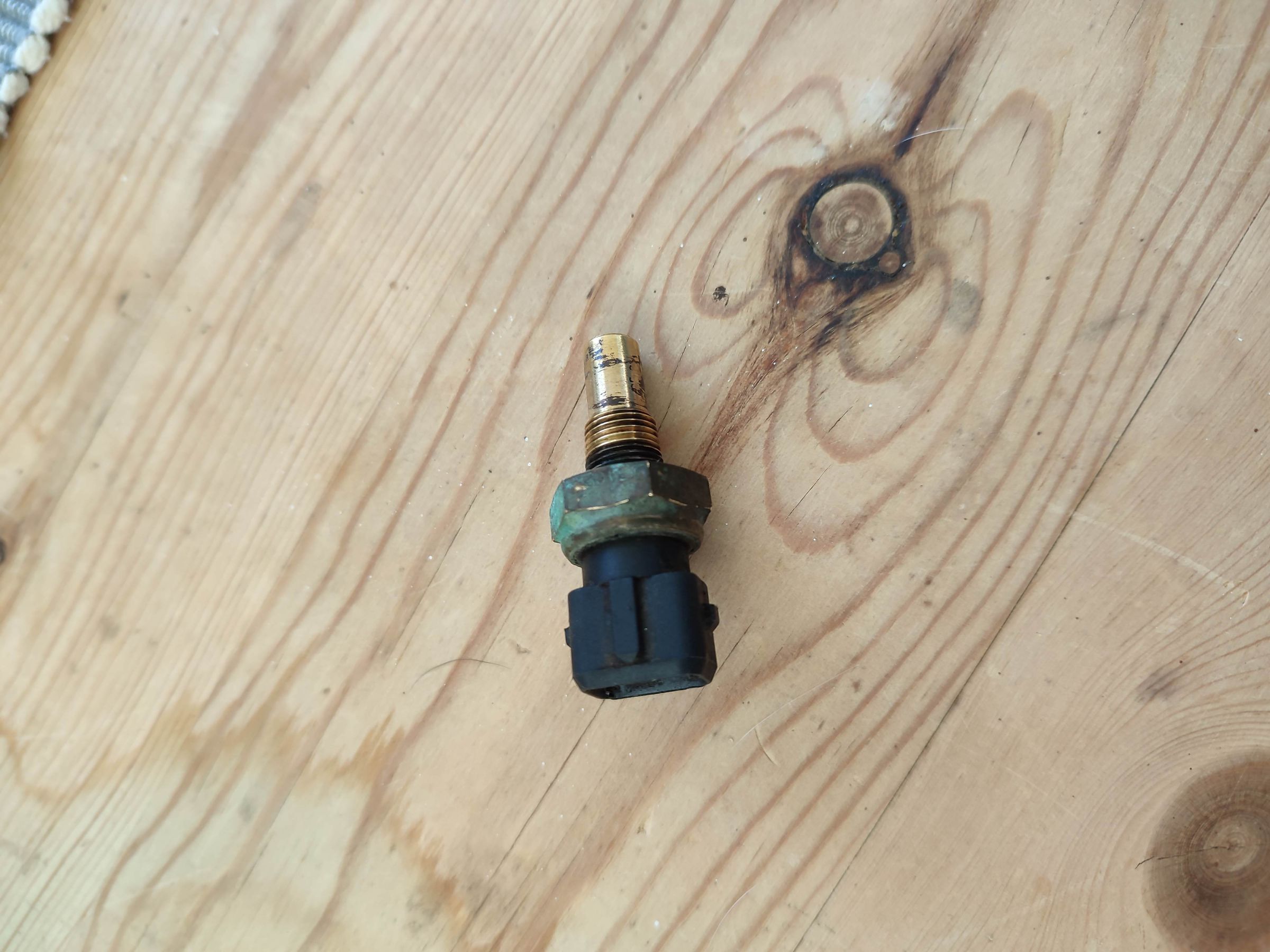
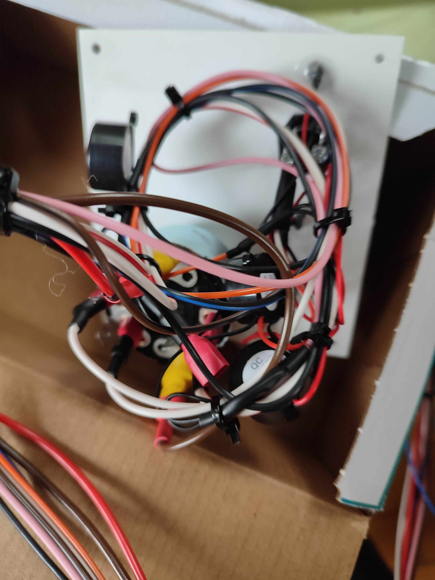
Now installed the new panel and finished testing. Had originally decided to remove the existing sensor, test it then replace it and attach a gauge. As the gauge I bought came with a sensor I decided to use that. Before going to boat tested it at home with cold and 80 degree water. Resistance readings at these temperatures were 5k and 300 ohms. Also found the gauge to be pretty accurate, so not bad for £6 off ebay. Installed the panel, new gauge and sensor and started the engine. All works pretty well, nice to have the oil light go out instantly and the warning buzzers too. The original issue of having to rev engine to get charge light remains, however as I now have a working oil warning light, not so much of an issue any more. Probably look into changing alternator as and when. I also sorted the wiring loom and made a bracket for the relay so it sits the right way up. When I tested the old sensor I got resistance readings of 5k cold water and about 400 ohms at 80 degrees. Thanks again for everyone's help.
-
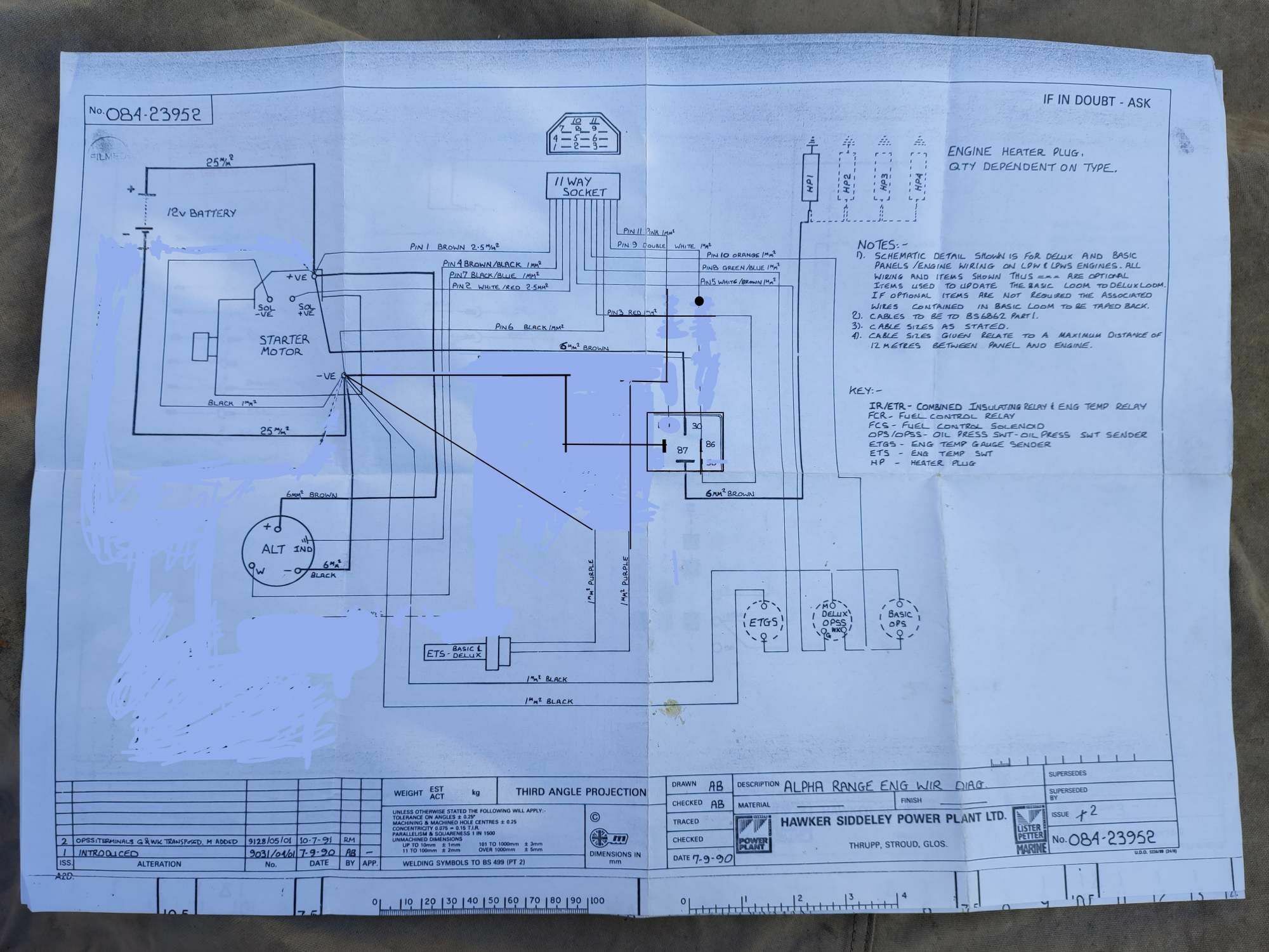
No diagram, however I sent them my original diagram and redesigned diagram and as you would expect for the price it all matches up, even the colours of the wires. Also the connector (11 way) is the same as the one on the boat, so it's just plug and play. I don't have the IR/ETR as it had already been replaced but happy to send you the VDO panel if you want it. I obviously won't need it when I build my own spare from the original panel.
-
New panel has arrived so will be cracking on with the testing and fitting - hopefully finished by Monday
-
Yes definitely will do, don't really want to have to buy another set of tools just to make new fuel pipe, if I can help it.
-
Called sleeman this morning and the chap I spoke said the thread on top hole is 1/8 NPT and the bottom is 3/8 NPT. They have both a switch 915-14032 (normally open cct) and sender 710-41275 and adaptor for bottom hole 757-17400 all in stock. Switch £23 +vat Sender £20 +vat Adaptor £6 + vat Going to carry out test on existing sender later this week, if that works I'll order new switch and and adapter to fit once I alter the fuel pipe to accommodate fitting
-
Yes you're right I'll ring them tomorrow see what that say
-
You don't happen to know the thread size of the lower plug, I think it's larger than top one, which JonathanA said is 1/8 NTP.
-
That's very helpful many thanks
-
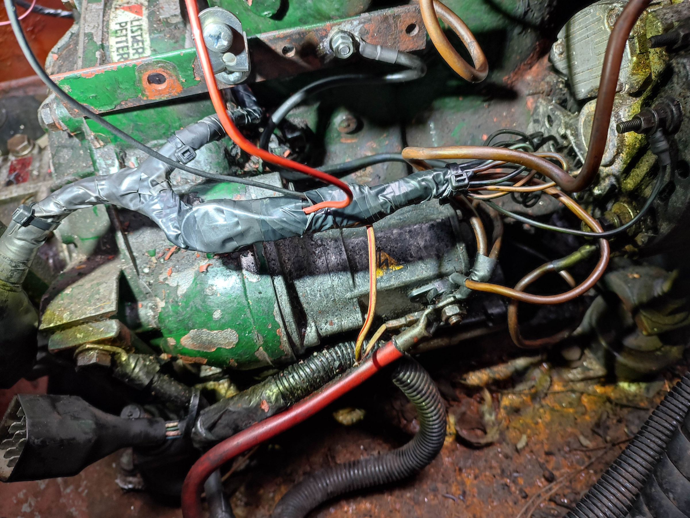
Yes I was also wondering if I could use the second plug instead, from my photo not sure if that pipe (believe it's fuel) is in the way, difficult to tell from photo. Will check on next vist
-
OK so looks like I'll have to get a switch for the warning light to work, suppose I could buy a cheap ebay gauge for now and wait until I do a coolant change to get a new switch. I'll probably get one that does both functions, they sell them on dragon marine systems. Anyone any idea of the thread size of temperature sensor on Lister LPWS2.
-
Yes diagrams look very similar except for your glow plug set up. Your wiring loom exactly same colours with same non used wires for oil and temperature senders 5 and 8 and Tachometer wire on 7. Did you ever do any tests on temp switch.
-
Yes I have to honest, I'm not sure what exactly it is. Another test I did was to rig up a 12v bulb cct and ran it to +ve and -ve on the battery, but through the switch and at its current state (5kohms) the bulb doesn't light. My thinking being that once the resistance reaches a low enough value the bulb will glow. I was making this assumption because on the combined relay the L terminal appears to have been the temperature warning light wire. That said never got the bottom of how that relay worked. I ran out time yesterday but my next plan was to take the switch/sender out of the engine and test it with boiling water.
-
This hopefully, will be the new cct diagram