pt2583
-
Posts
47 -
Joined
-
Last visited
Content Type
Profiles
Forums
Events
Gallery
Blogs
Store
Everything posted by pt2583
-
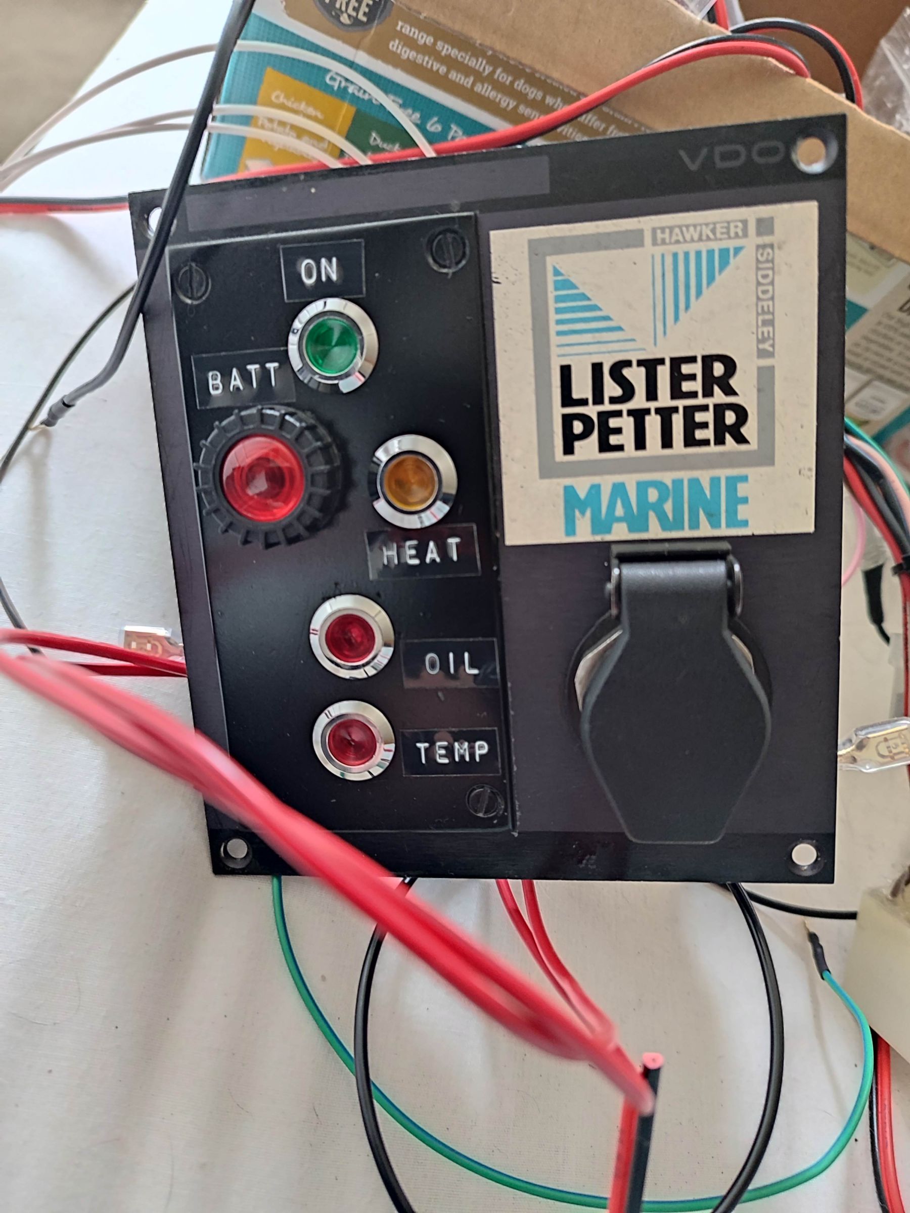
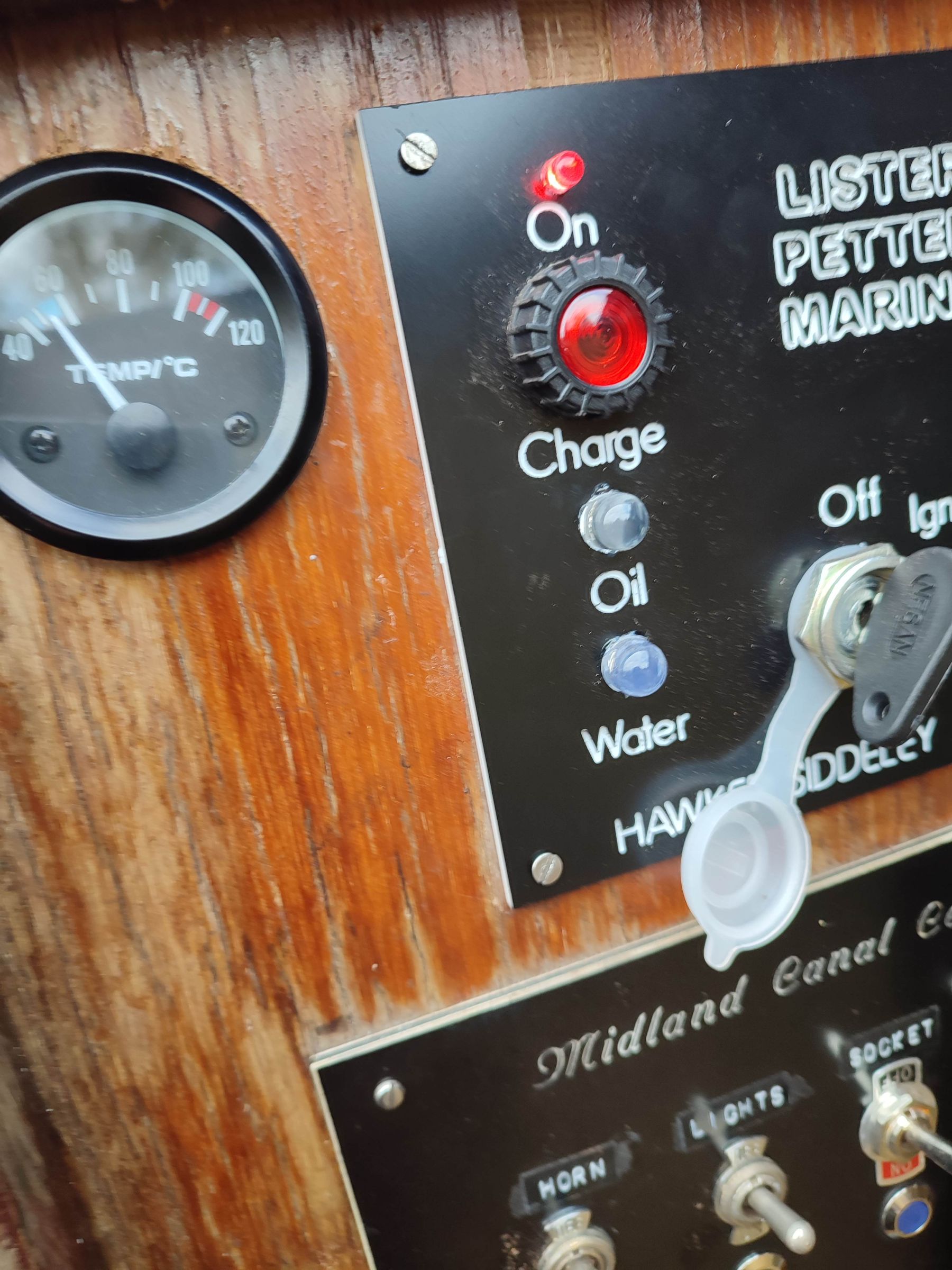
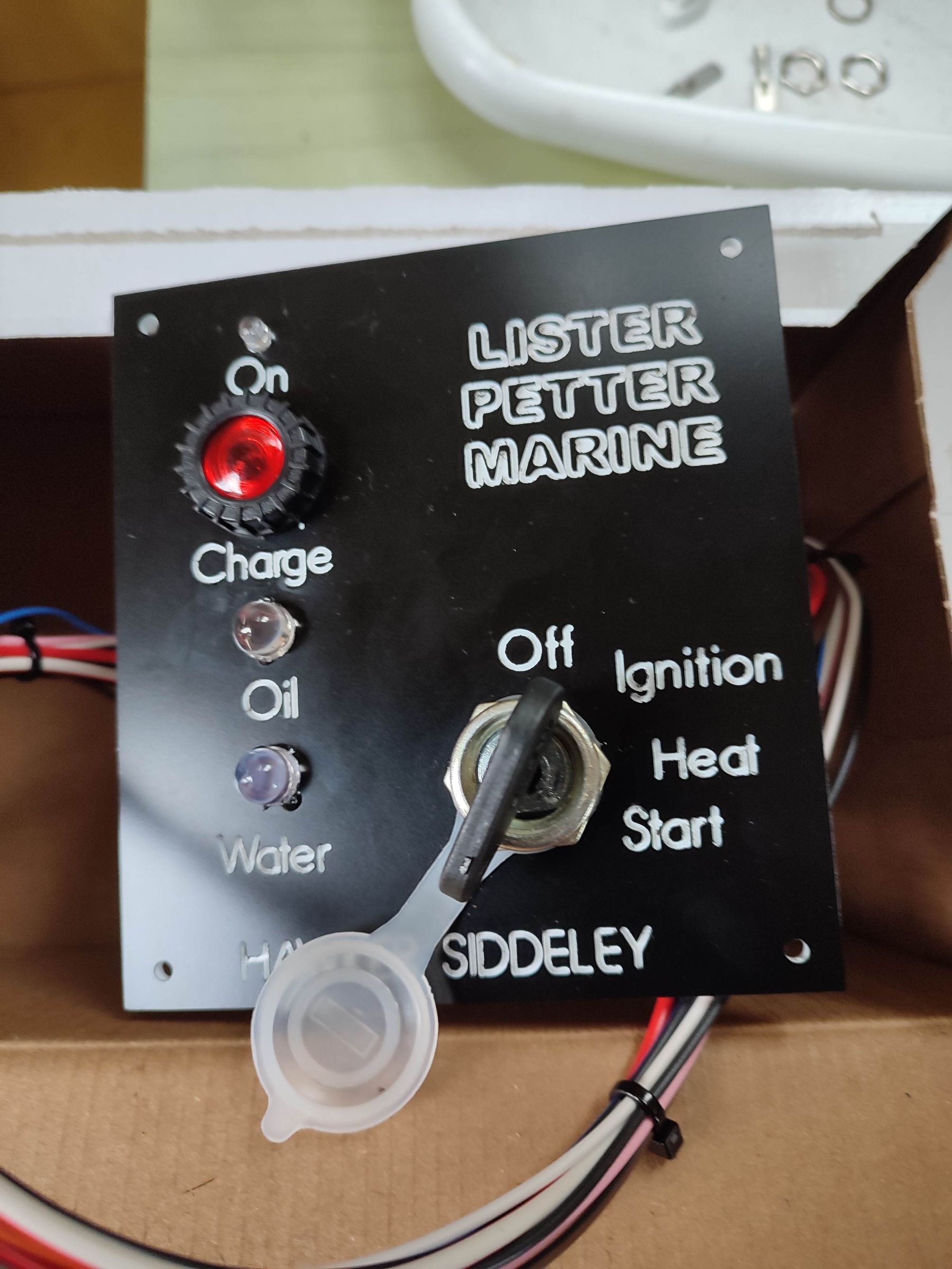
Final update. I found that upgrading the bulb in the charge/battery cct from a 2w to 3w made a significant change to the alternator excite behaviour. It now only needs a little blip of the throttle and the light goes out. So problem finally solved. I have now also finished the changes to the original instrument panel. Instead of a buzzer on the glow plug heat cct, I added an orange led light. So now have a spare instrument panel

-
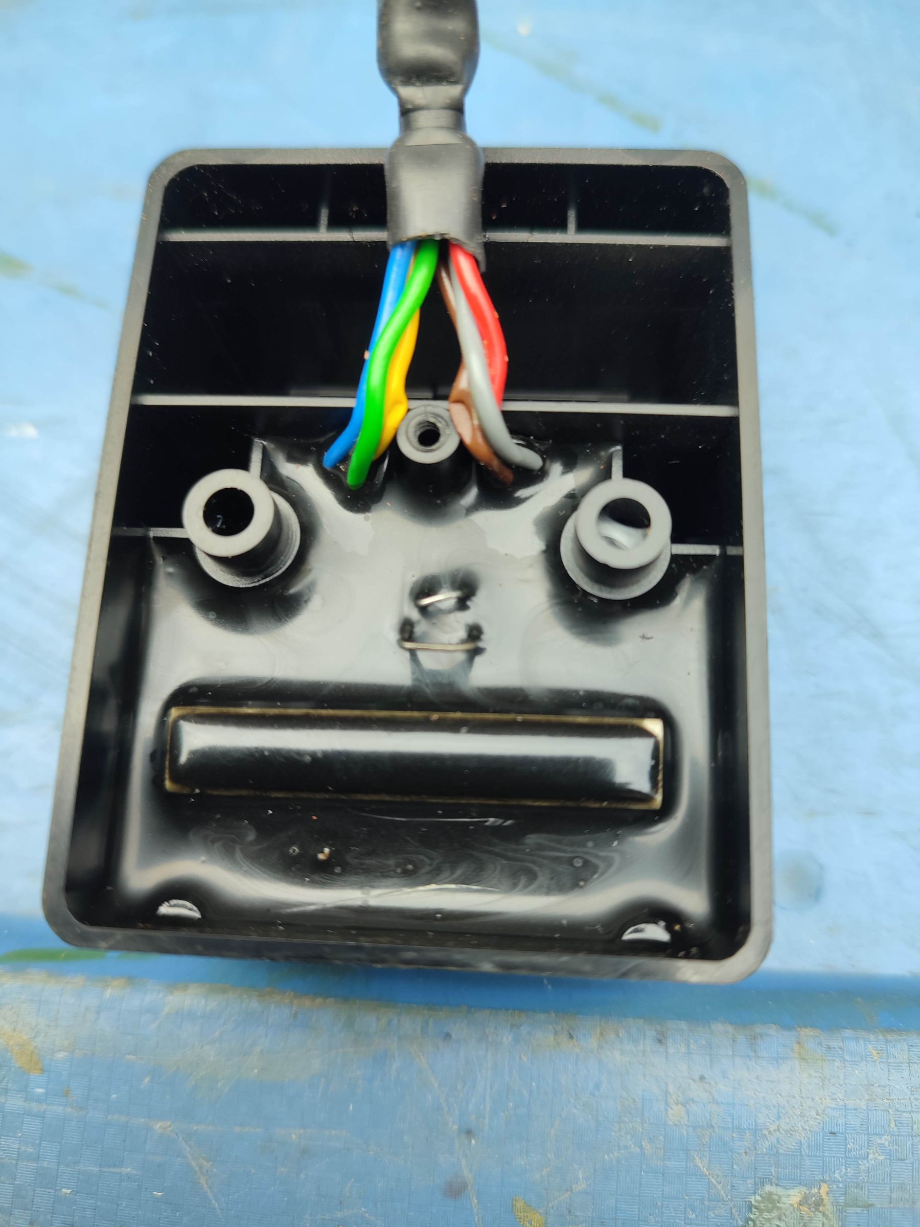
This is internal of the alarm unit. All sealed with epoxy resin. Doubt you could get it apart without destroying it That's very handy to know, been trying to figure out which one it was. They seem to be pretty cheap
-
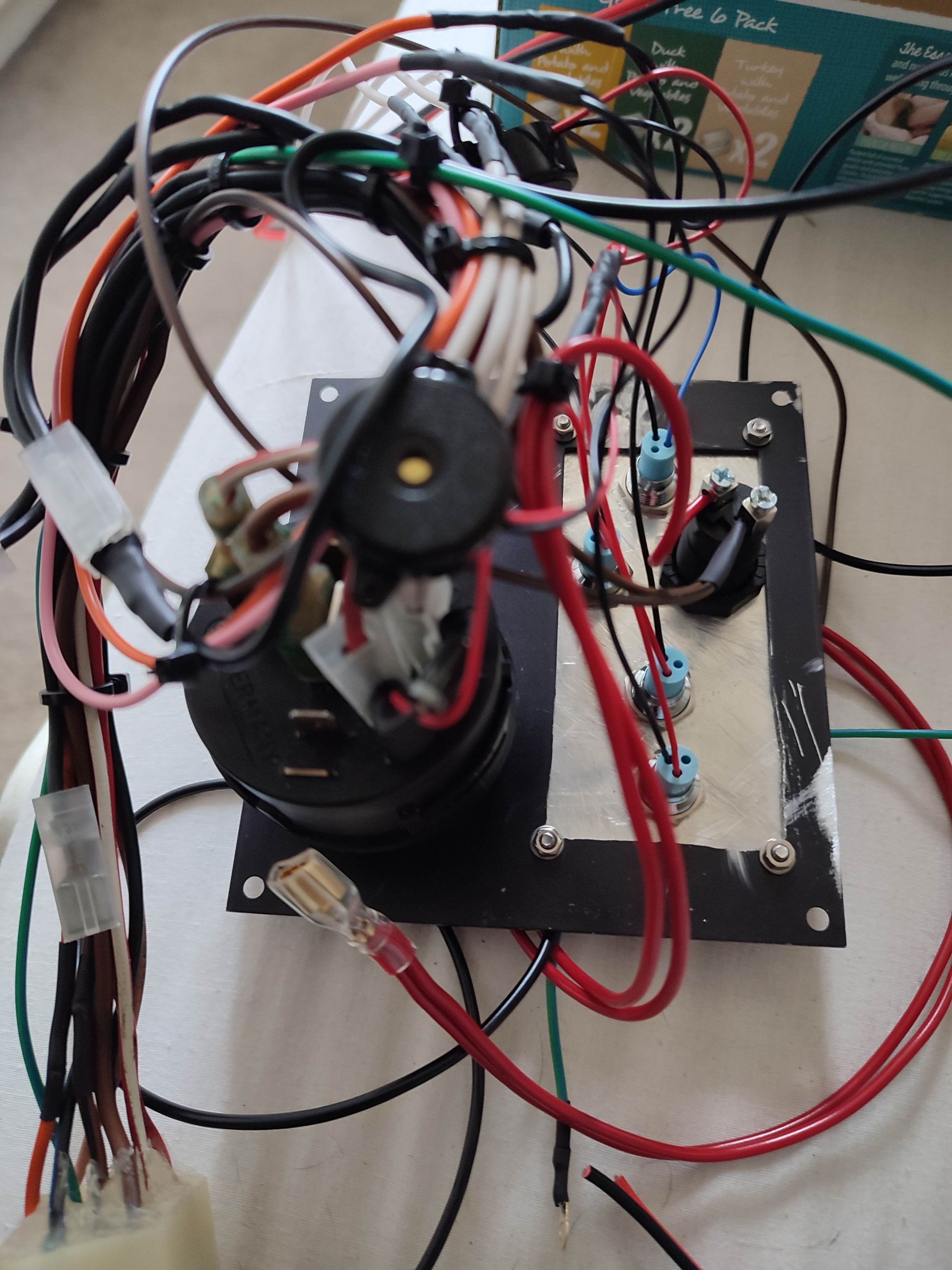
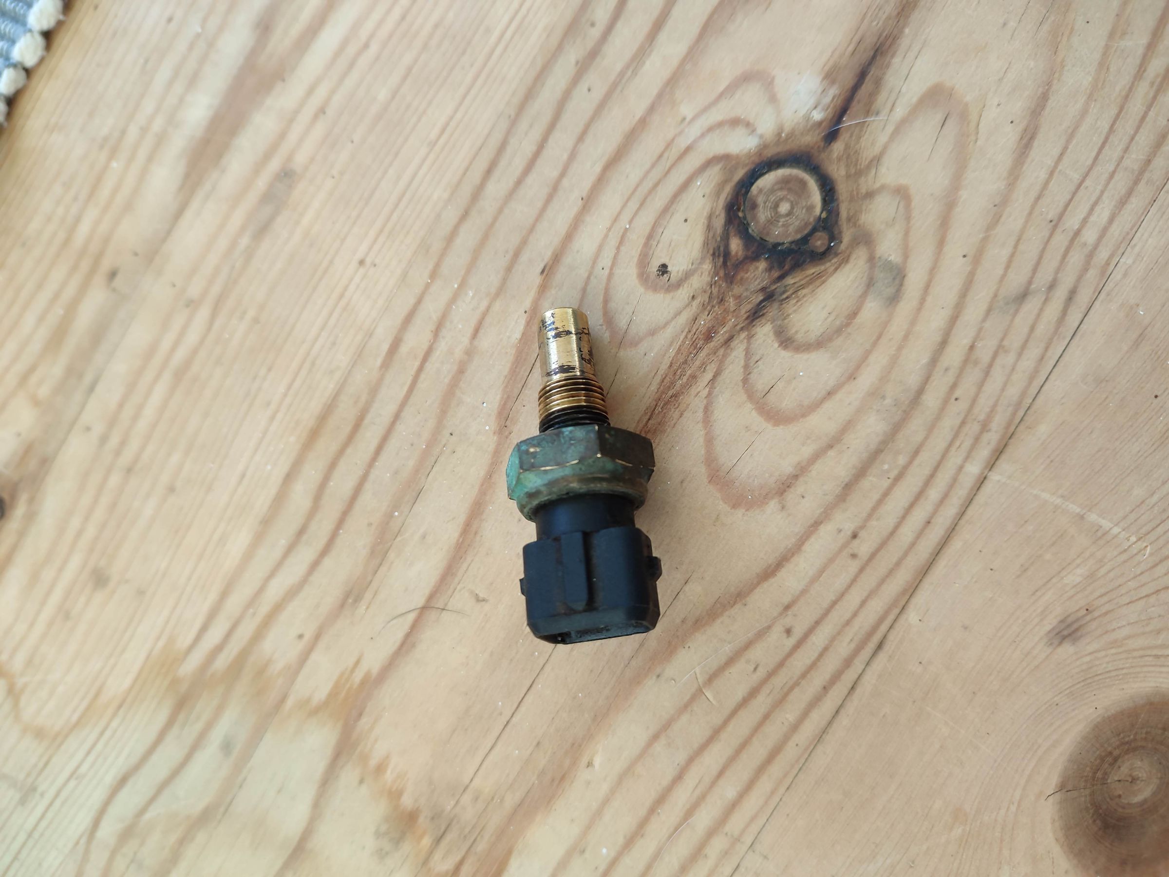
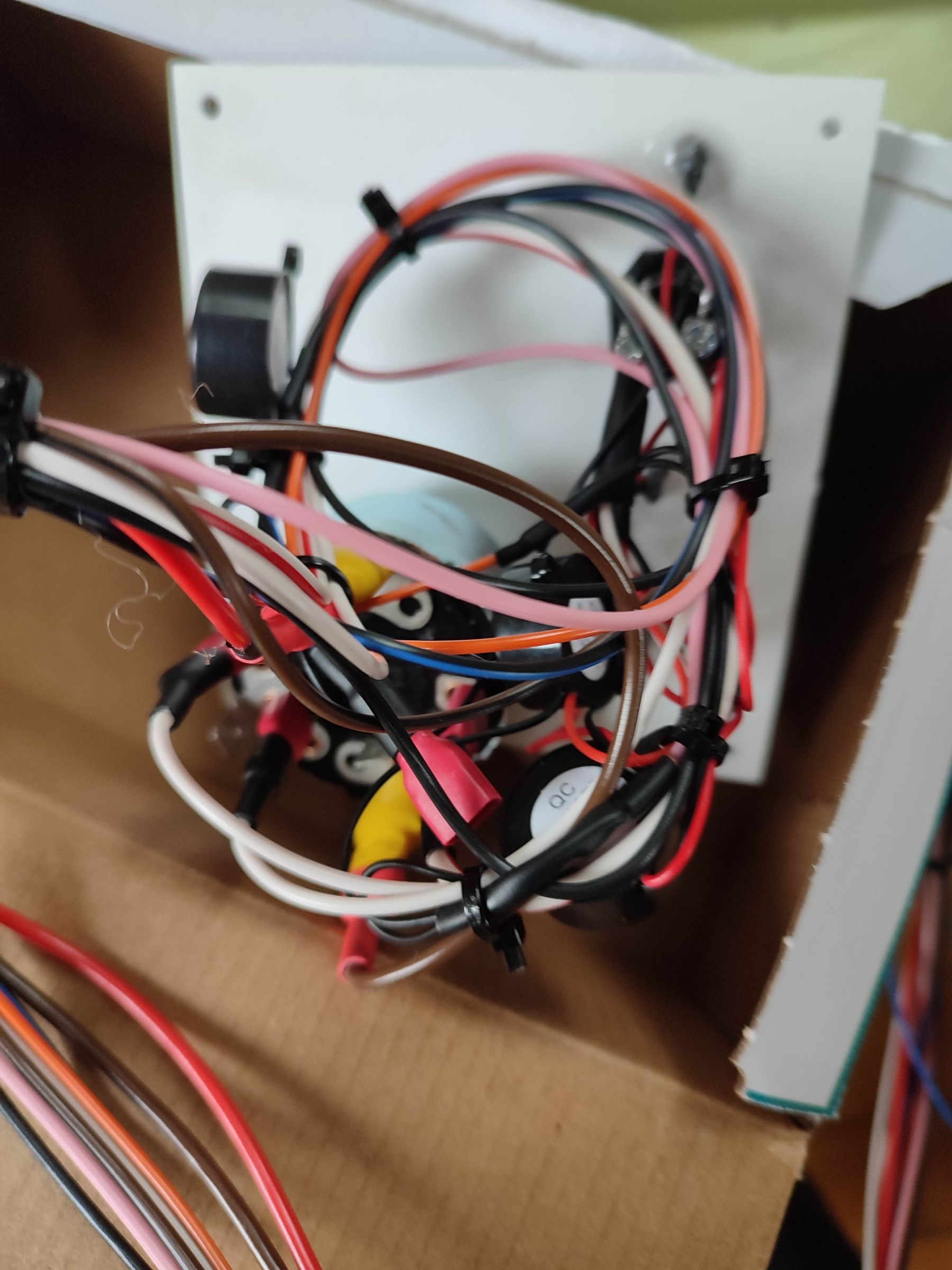
Now installed the new panel and finished testing. Had originally decided to remove the existing sensor, test it then replace it and attach a gauge. As the gauge I bought came with a sensor I decided to use that. Before going to boat tested it at home with cold and 80 degree water. Resistance readings at these temperatures were 5k and 300 ohms. Also found the gauge to be pretty accurate, so not bad for £6 off ebay. Installed the panel, new gauge and sensor and started the engine. All works pretty well, nice to have the oil light go out instantly and the warning buzzers too. The original issue of having to rev engine to get charge light remains, however as I now have a working oil warning light, not so much of an issue any more. Probably look into changing alternator as and when. I also sorted the wiring loom and made a bracket for the relay so it sits the right way up. When I tested the old sensor I got resistance readings of 5k cold water and about 400 ohms at 80 degrees. Thanks again for everyone's help.
-
No diagram, however I sent them my original diagram and redesigned diagram and as you would expect for the price it all matches up, even the colours of the wires. Also the connector (11 way) is the same as the one on the boat, so it's just plug and play. I don't have the IR/ETR as it had already been replaced but happy to send you the VDO panel if you want it. I obviously won't need it when I build my own spare from the original panel.
-
New panel has arrived so will be cracking on with the testing and fitting - hopefully finished by Monday
-
Yes definitely will do, don't really want to have to buy another set of tools just to make new fuel pipe, if I can help it.
-
Called sleeman this morning and the chap I spoke said the thread on top hole is 1/8 NPT and the bottom is 3/8 NPT. They have both a switch 915-14032 (normally open cct) and sender 710-41275 and adaptor for bottom hole 757-17400 all in stock. Switch £23 +vat Sender £20 +vat Adaptor £6 + vat Going to carry out test on existing sender later this week, if that works I'll order new switch and and adapter to fit once I alter the fuel pipe to accommodate fitting
-
Yes you're right I'll ring them tomorrow see what that say
-
You don't happen to know the thread size of the lower plug, I think it's larger than top one, which JonathanA said is 1/8 NTP.
-
That's very helpful many thanks
-
Yes I was also wondering if I could use the second plug instead, from my photo not sure if that pipe (believe it's fuel) is in the way, difficult to tell from photo. Will check on next vist
-
OK so looks like I'll have to get a switch for the warning light to work, suppose I could buy a cheap ebay gauge for now and wait until I do a coolant change to get a new switch. I'll probably get one that does both functions, they sell them on dragon marine systems. Anyone any idea of the thread size of temperature sensor on Lister LPWS2.
-
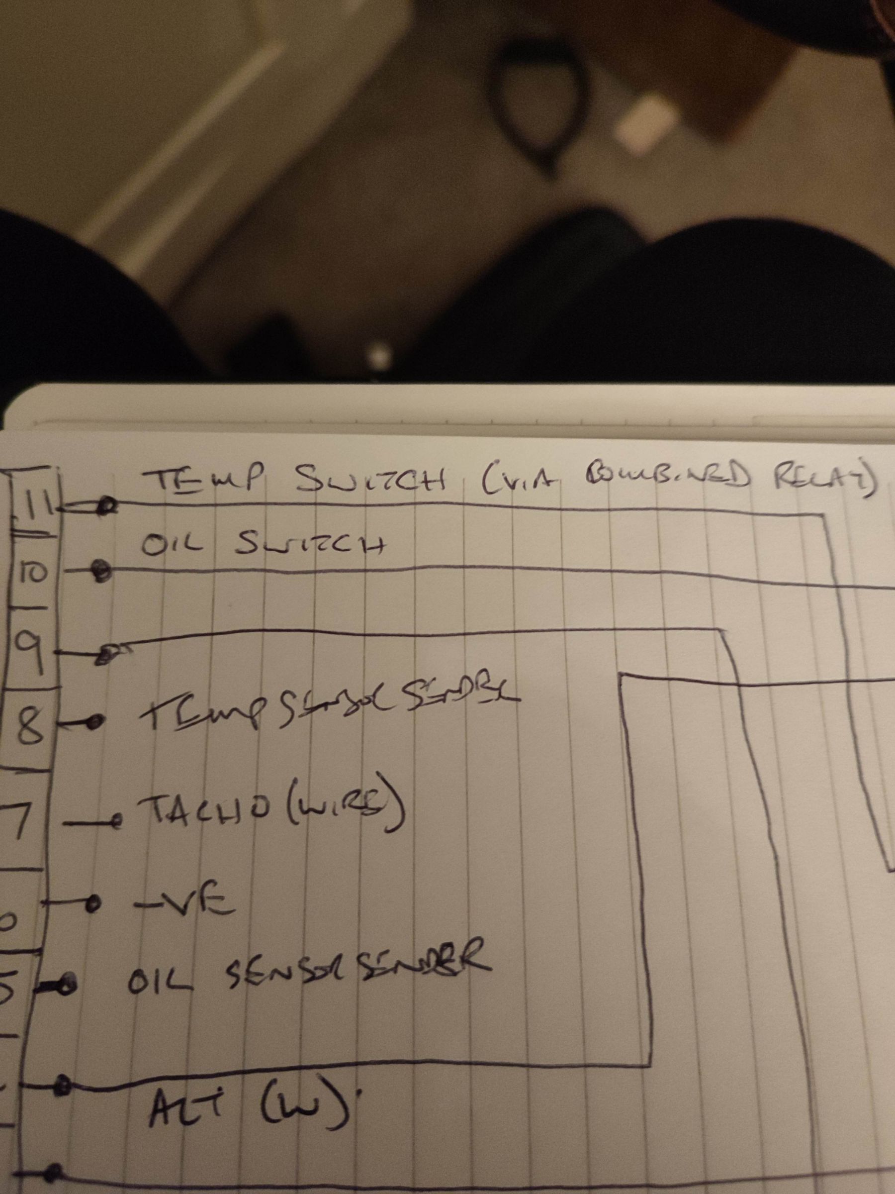
Yes diagrams look very similar except for your glow plug set up. Your wiring loom exactly same colours with same non used wires for oil and temperature senders 5 and 8 and Tachometer wire on 7. Did you ever do any tests on temp switch.
-
Yes I have to honest, I'm not sure what exactly it is. Another test I did was to rig up a 12v bulb cct and ran it to +ve and -ve on the battery, but through the switch and at its current state (5kohms) the bulb doesn't light. My thinking being that once the resistance reaches a low enough value the bulb will glow. I was making this assumption because on the combined relay the L terminal appears to have been the temperature warning light wire. That said never got the bottom of how that relay worked. I ran out time yesterday but my next plan was to take the switch/sender out of the engine and test it with boiling water.
-
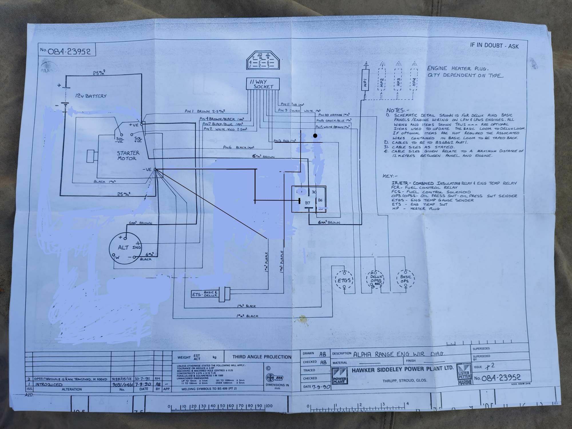
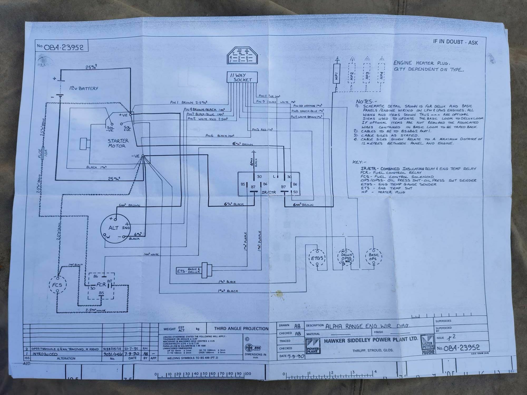
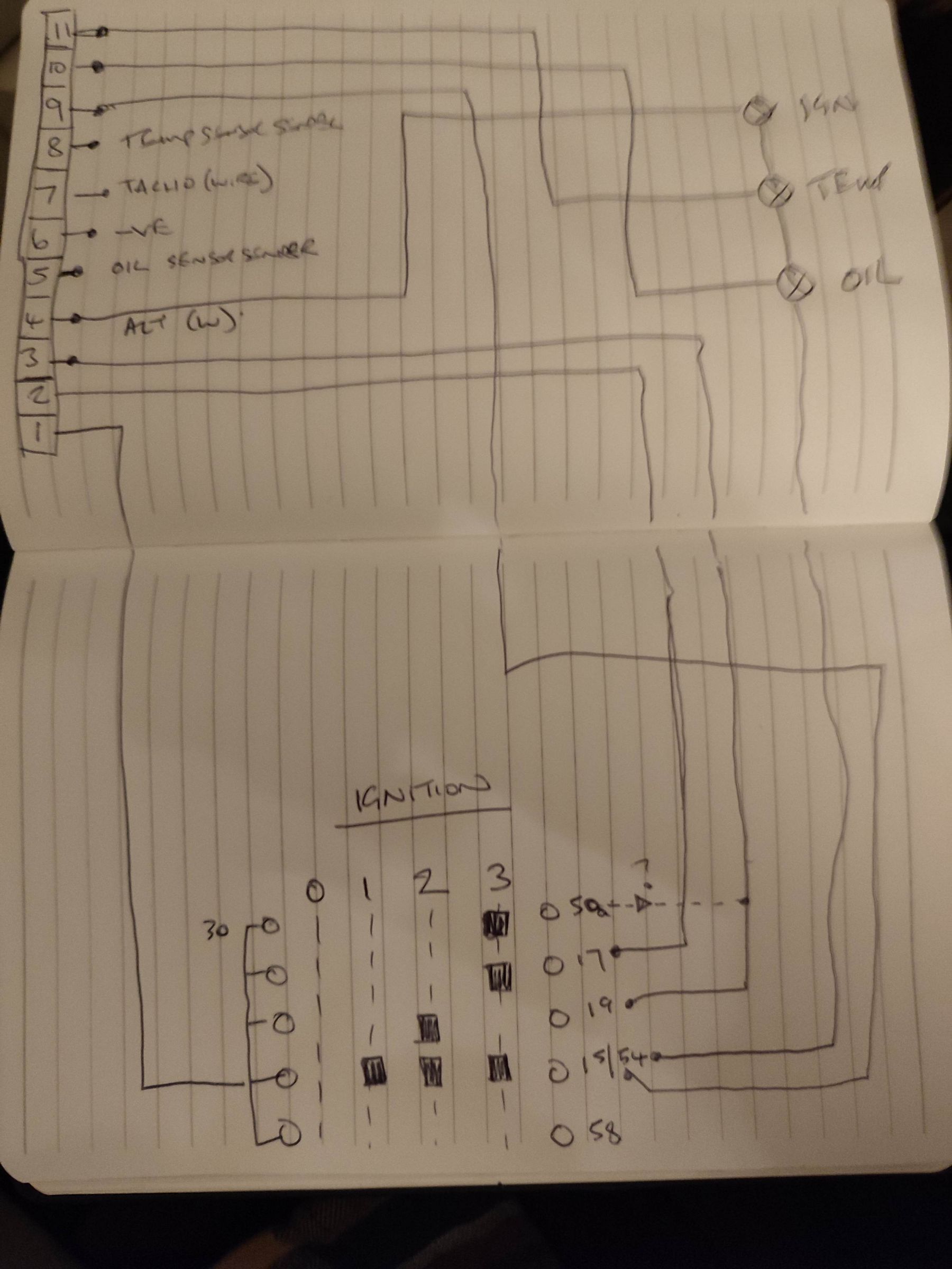
This hopefully, will be the new cct diagram
-
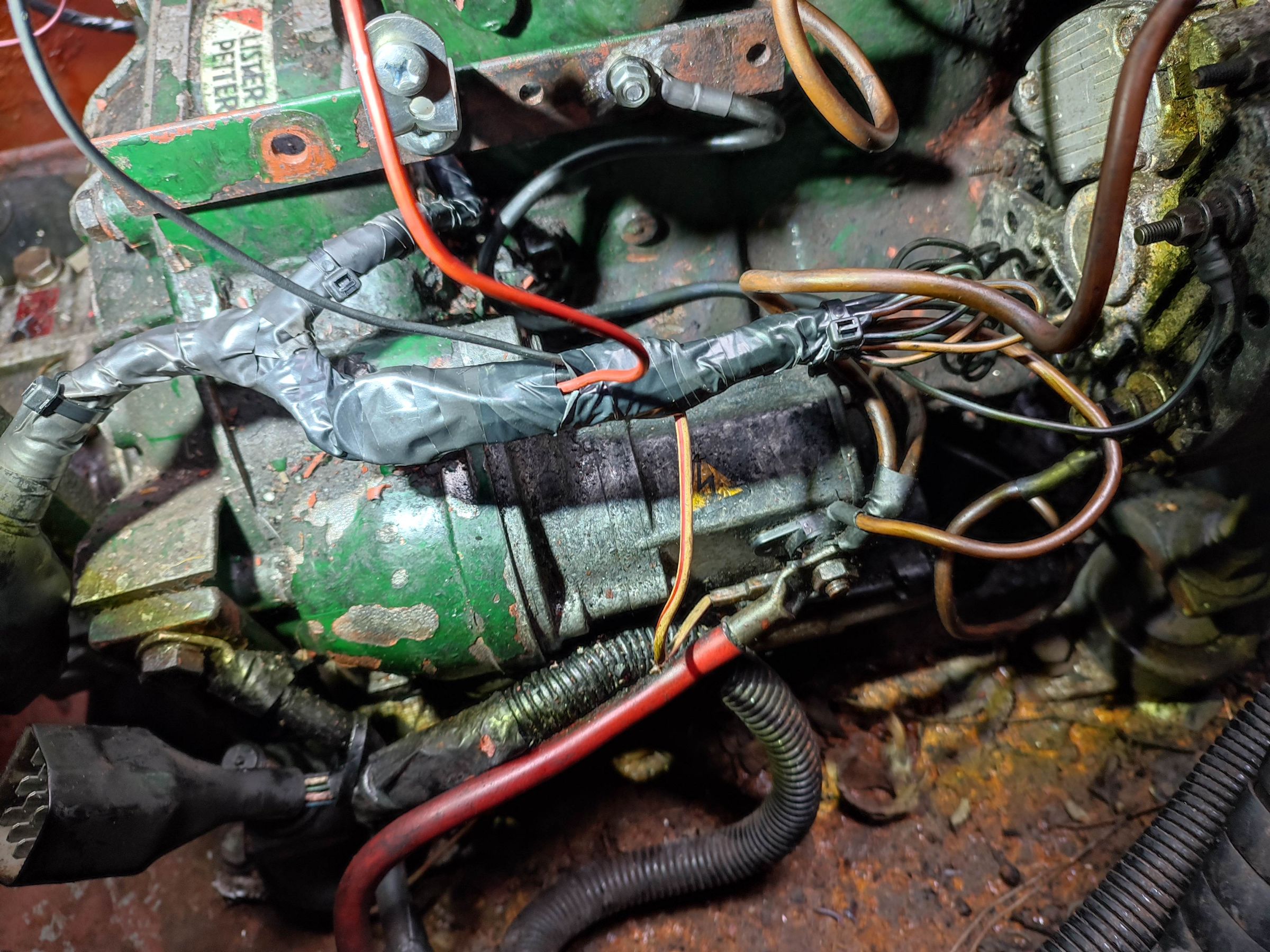
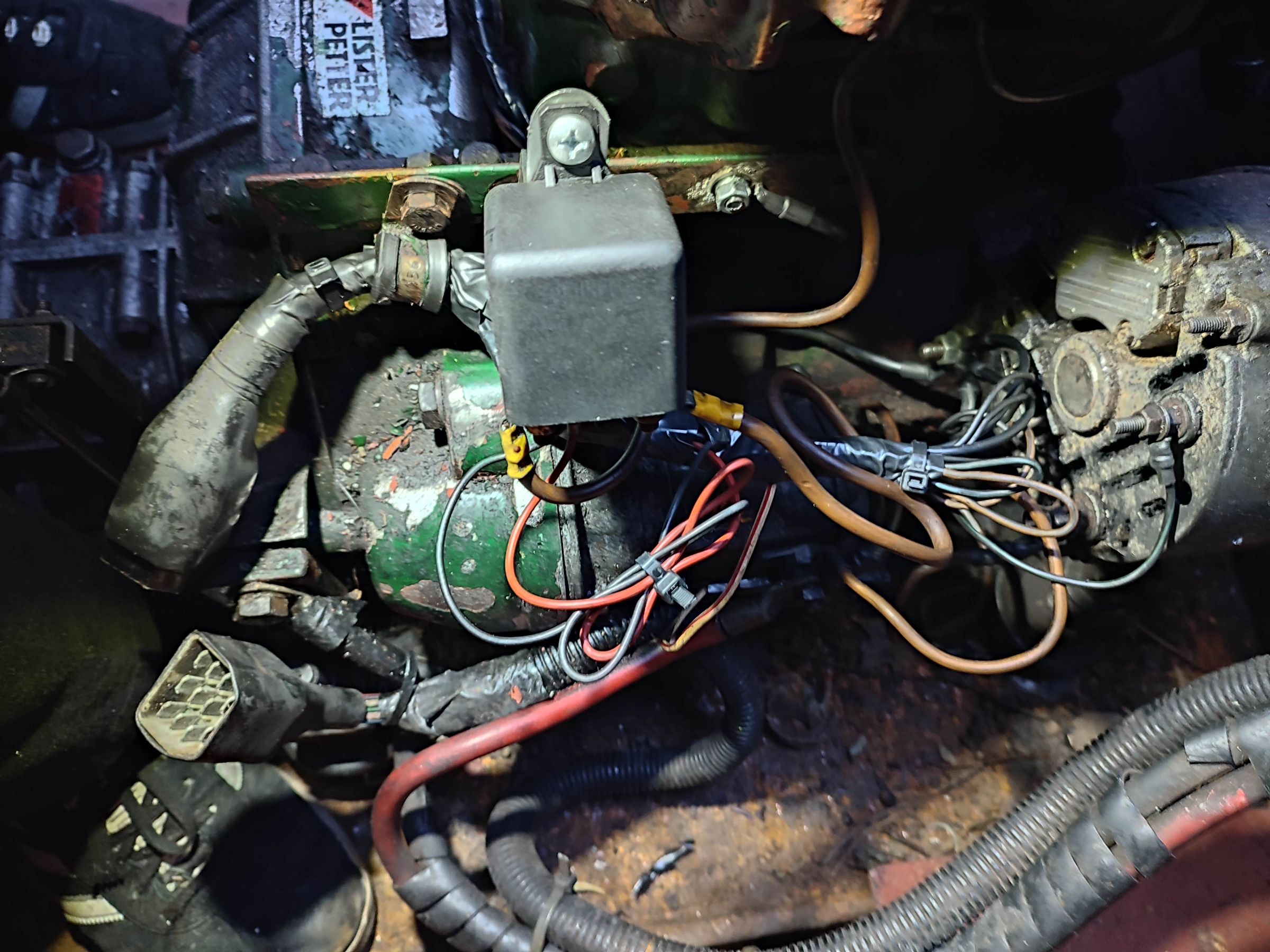
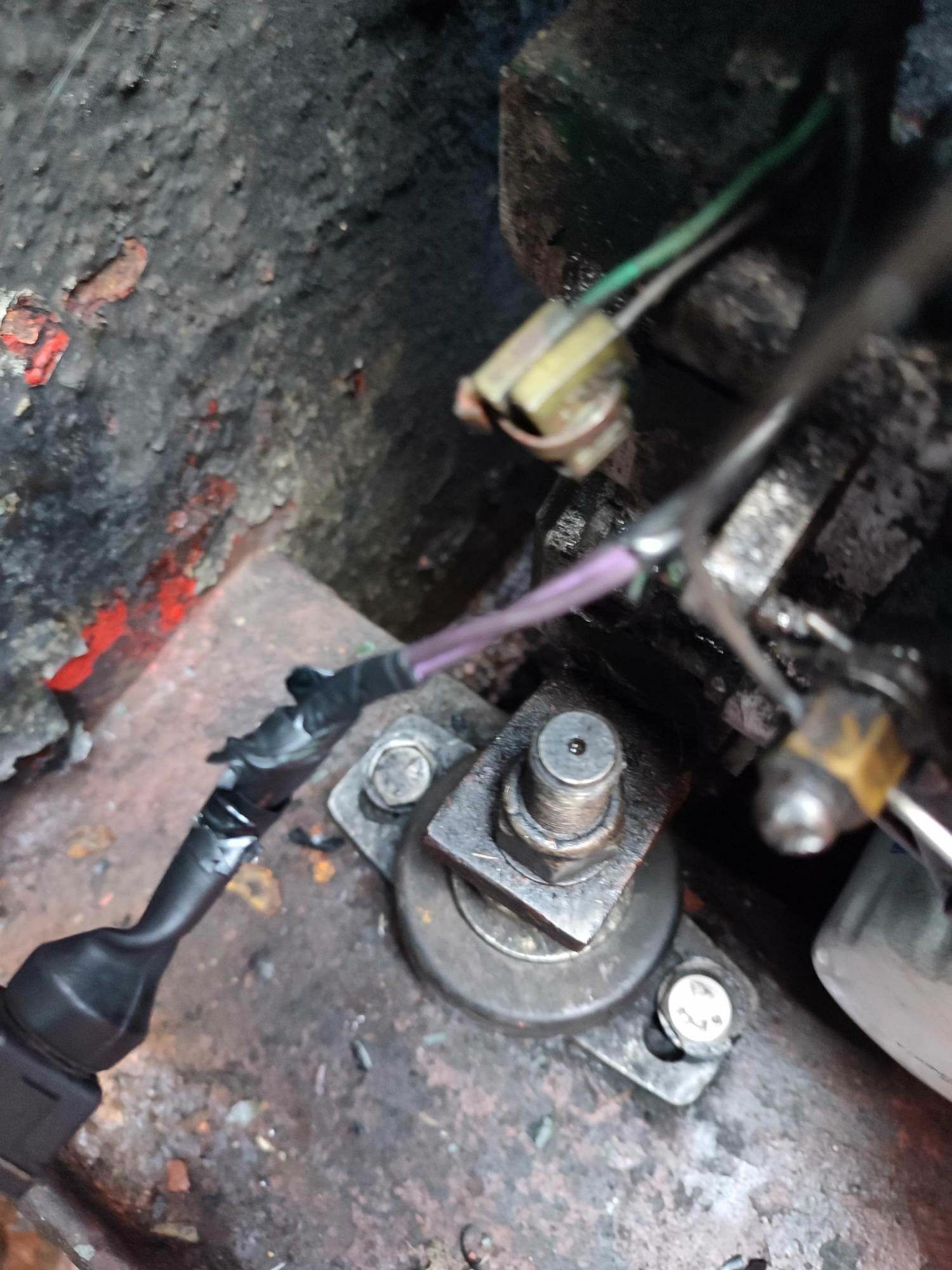
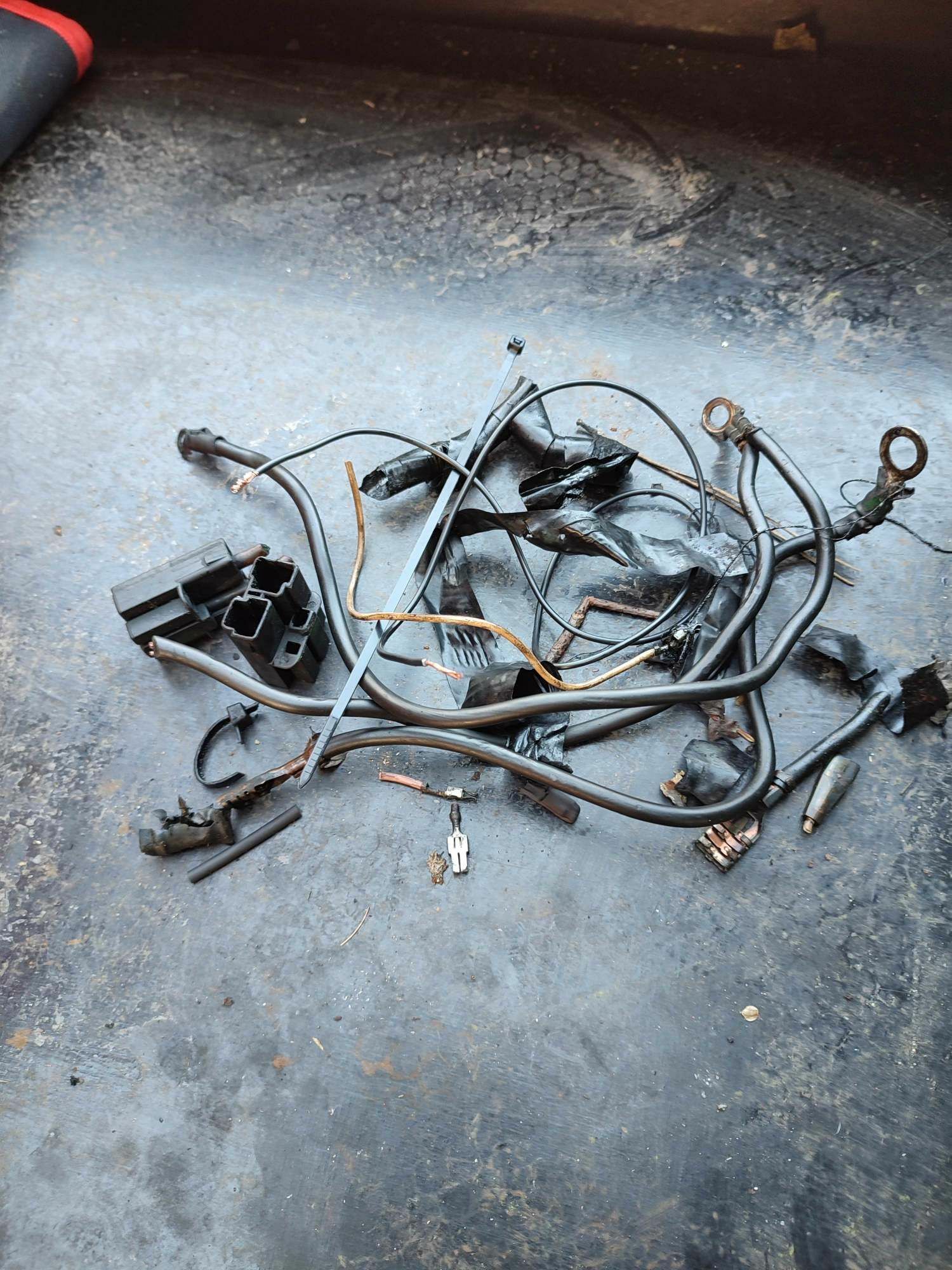
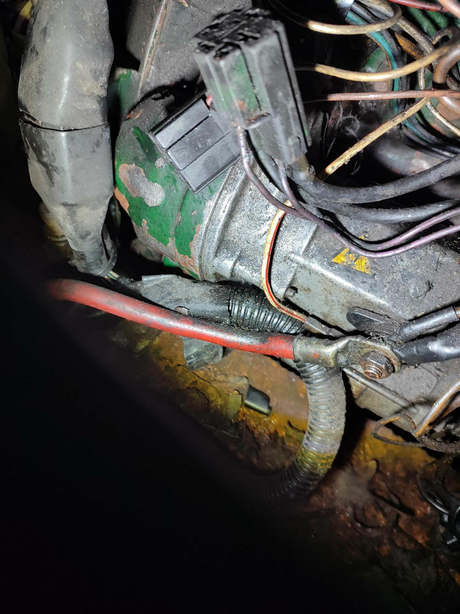
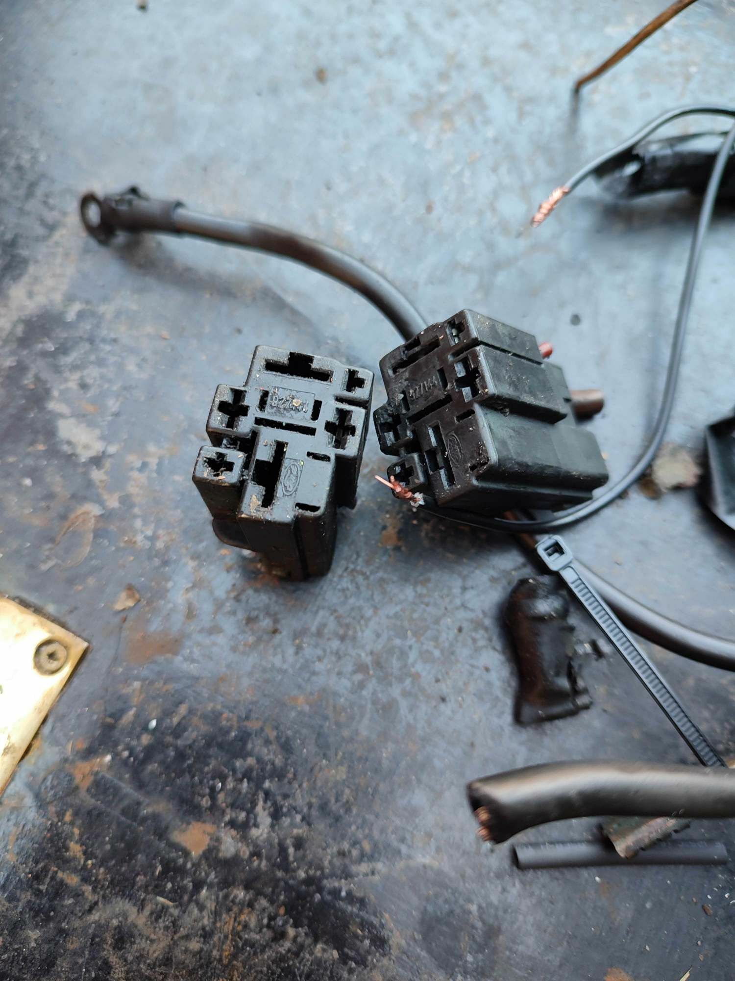
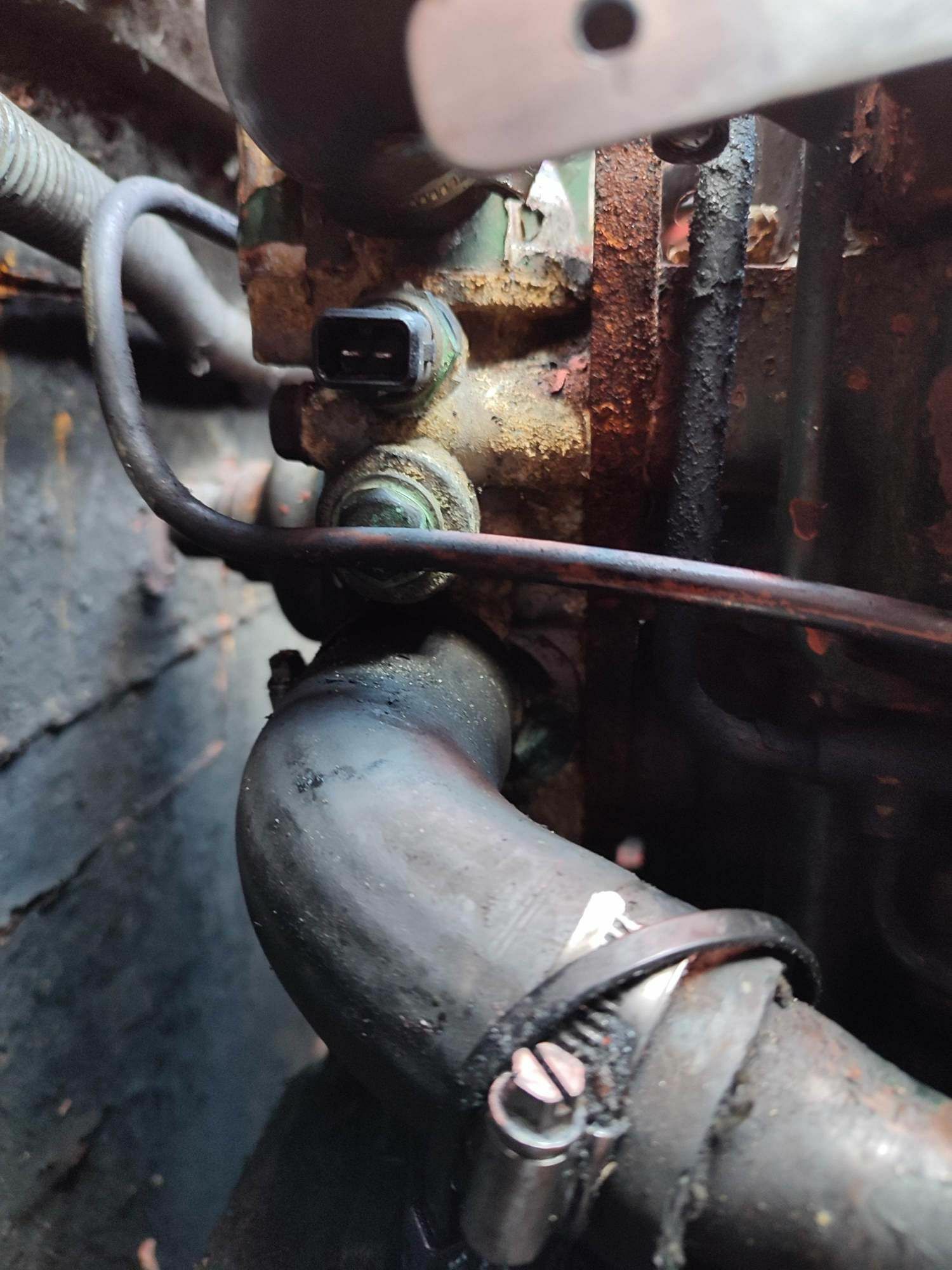
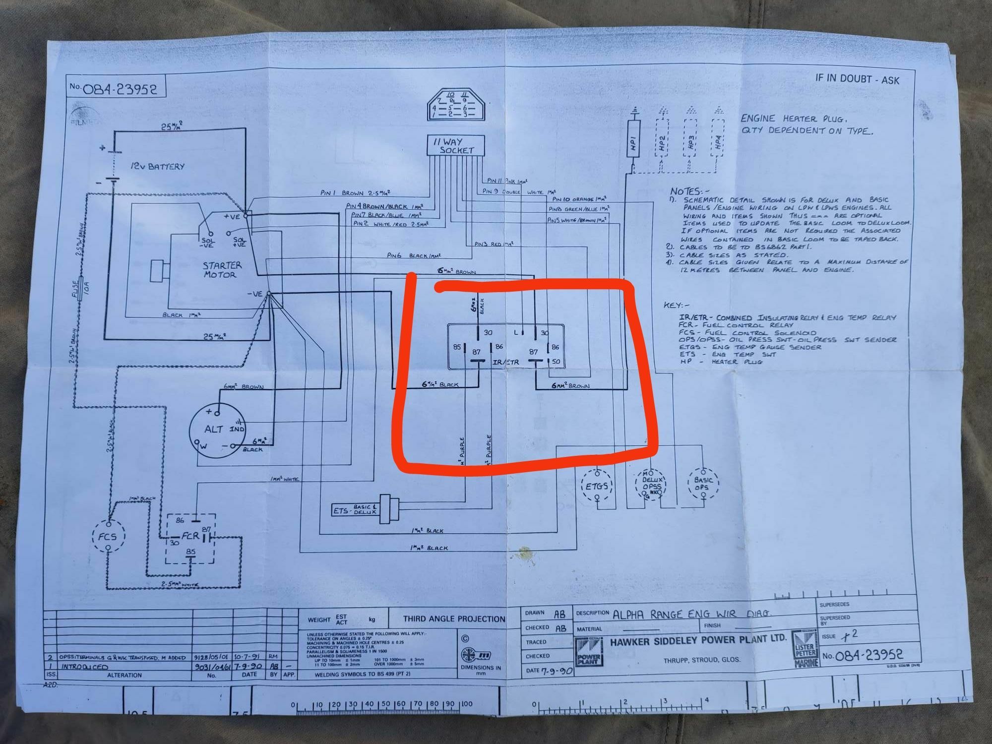
Spent day at boat again today. Further investigation in daylight found that the original combined relay had two connectors (see photo). Colours of all cables matched cct diagrams, however apart from the two 6mm brown cables and red wire from ignition none of the wires were connected. Whoever fitted the new relay ran a new -ve from the relay bracket mounted on engine. Would appear one of the black 6mm cables was ground somewhere but this was also disconnected. This means the alternator has no direct -ve connection, presumably its connection to -ve is via connection bolts to engine. So on to the temperature switch shown on diagram connected to relay via two purple wires. My one and only switch is indeed fed by two purple wires and test with multimeter found they are the two purple wires originally connected to relays. However as these connectors are no longer connected to any thing my temperature switch is in fact disconnected. I did a resistance test this morning when it was about 6 degrees and the resistance across two contacts of switch was 5.3 kohms. Some Google ING seems to suggest this is about right for this temp. Neither of the switch contacts seems to be connected to -ve through the engine so what I plan to do is run a -ve to one purple wire and then connect the other purple wire to temperature warning light contact on the 11 way plug. So if the switch works correctly (100 ohms resistance at about 100 degrees) the bulb should light. In one of the pictures showing the two purple wires you can also see the two wires from the loom which would be used for a temperature gauge, only installed on deluxe module. Not sure if these would be connected to a second switch where there is currently a plug bolt.
-
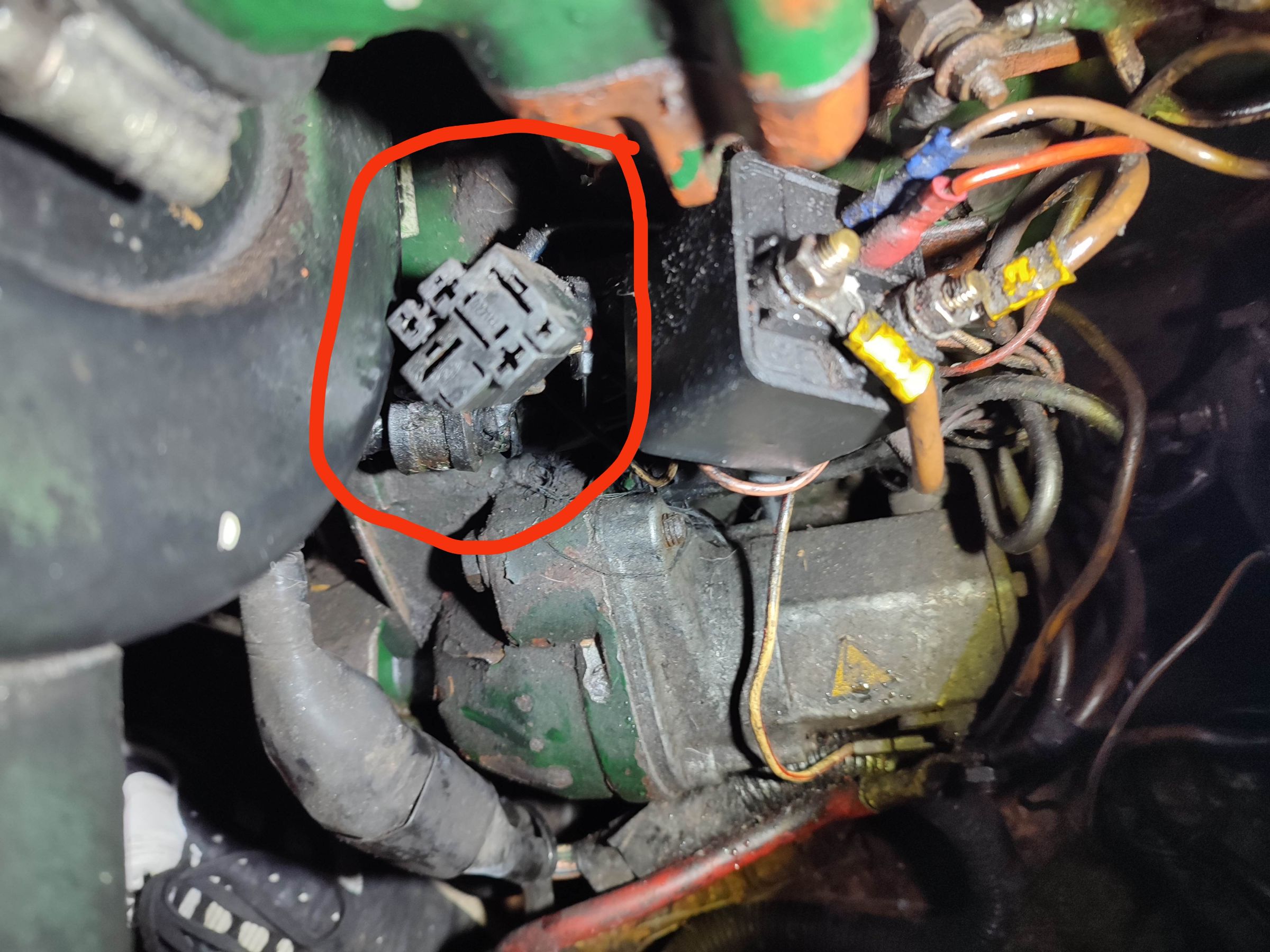
Been to the boat tonight and although it was dark took a picture of the relay and did a bit of prodding around the wires. Too dark to do any proper tracing will leave that for day light hours. Discovered that the relay has in fact already been changed to a simple 4 contact (85,86,87,30) heavy-duty relay. The power in and out to glow plug wires (6mm brown) and +ve and - ve wires have been cut from the original 6 way connector plug and attached to the new relay. This means I don't have pre heat function and more of a worry don't know if the temperature switch wires are even connected to anything anymore. Will now have to trace them out to confirm they are. Perhaps should have done all this first, but have to say its been worthwhile for me as I've learnt a lot from what's been said.
-
If my memory serves me correctly the relay on my boat does not look exactly the same as the way its drawn in the diagram, but then again you probably wouldn't expect it to as its a schematic diagram. When I'm next on the boat in day light, at the weekend, I'll take some pictures and maybe do a bit of wire tracing see if I can work it out and let you know. This relay is really the last puzzle on my boat that I want to solve, as I like to know how things work, so I can try fix if they go wrong. After all it's not like car, you can't just take it to the nearest garage 🤣🤣🤣.
-
On my panel there is no glow plug light and the engine temperature warning switch sits across contacts 85 and 86, I think. Some how the switch activating is using the light terminal on the relay to, presumably, send earth back to the temperature warning light on panel.
-
This is fantastic info, many thanks 👍
-
Not sure on that 🤔
-
That's just what it says in operation manual, however as its on a temperature switch (I presume only open or closed) I don't see how it knows what the temperature is. I suppose if it refers only to the deluxe model where a temperature sender is used instead, it might work then 🤔
-
Yes there is a relay, but for the life of me can't fathom out exactly how it works. It described as a combined insulation relay. Also incorporates the control of temp monitor switch. Any help with understanding this would be greatfully appreciated
-
Yes the one I've ordered will have warning buzzer, also have add them to my build
-
Hi, thanks for this info, I'm planning on changing the electronic module for simple lights. I take it then I'll still need the diode.