Jen-in-Wellies
Moderator-
Posts
6,941 -
Joined
-
Last visited
-
Days Won
32
Content Type
Profiles
Forums
Events
Gallery
Blogs
Store
Everything posted by Jen-in-Wellies
-
All depends on the water leve!s. The EA were keeping them very low in 2013 by all accounts and winding was completely impossible. Had lines taken to the bank and tried to haul the boat round from there after the engine wasn't enough, but just not enough water and too much mud! It is an interesting waterway. Once you go through the one lock you can see across the countryside, rather than just the flood defence bank to either side as on the Witham. The village is delightful. Jen
-
The tidal Trent needs treating with respect. Inattention, or bad luck can lead to a scary epic. Nav lights are a requirement. VHF is useful, but I would say not essential these days with improved mobile coverage. I have it. I always take advice from the lock keepers on duty at the tidal locks for times to go. They know their stuff. In a narrowboat I usually do Keadby - Cromwell over two days in either direction as otherwise you'll be against the tide and slow right down for a lot of the trip. Splitting it means most of the trip can be done with the tide helping you. Overnight on the pontoons below Torksey lock. The Sissons charts are important. There are a couple of spots where the deep channel is not obvious and if water levels are low you can easily go aground. Do that on a falling tide and you are stuck until it rises again. Don't cut corners! With preparation it is an excellent trip with lots of variety and a feel of a proper adventure. Well woerrth doing. Make sure your engine can run for hours at full power. This trip seems to show up cooling problems that never appear on canals and other rivers. Hope this helps, jen
-
Biggest thing I found was keeping the concentration needed to minimise contact for the time it takes to get through. As others have said, it is all very well organised, but I wasn't expecting to get all the paint through unscathed. Not to bad. A little lost from the handrail. Jen
-
It didn't seem so at the time! Quiet put me off "adventure boating" for a while. Certainly lost the desire to go on to the navigable drains around Boston later in the trip. Jen
-
Managed to get to the current end of navigation at Cobblers lock with a draught of 20" in 2013. Increasingly shallow beyond Kyme Eau and the boat was in tickover from Ferry Bridge on. Couldn't wind at all at Cobblers Lock due to silting up of the drain. Had to reverse the six miles back to Loswer Kyme lock. Took all day! My boat is 57' and there are a couple of places where a shorter boat may wind. If there isn't a more up to date info here then contacting the Sleaford Navigation Trust may help. After I went there was some dredging at lower Kyme lock that made getting past a lot easier. Jen
-
Sprinkle on by hand seems to work ok. The only stuff that will stick is the first to go down and soak in to the paint. Just add more till it stops soaking up paint and leave to dry. Vac off the excess when dry and overpaint to seal in. Jen
-
No standard for hinges. A picture or two would help us understand. Jen
-
Plenty of people on boats living in squalor today. Some of them still have registered in xxxxxxx just visible through the rust, so clearly not valid anymore! Jen
-
This post cannot be displayed because it is in a forum which requires at least 10 posts to view.
-
You should definitely be asking the cat where it has hidden them. Jenny Seriously, hope you find them OK.
-

Solar water collector connections
Jen-in-Wellies replied to Tom Richmond's topic in Boat Building & Maintenance
I would. Either another boat that was to be lived in most of the time, especially over summer, or even a house. Probably be more DIY rather than buying ready made modules now I have a better idea of what works and what doesn't. The plumbing around the pump and reservoir tank is usually hidden away. Jen -
Solar water collector connections
Jen-in-Wellies replied to Tom Richmond's topic in Boat Building & Maintenance
As you command! My system is based on one made by Aton Solar. Atonsolar.nl The collector is 8' x 4'. Oversized I hink. Makes walking down the roof tricky. Mounted to the roof with some rubber door stops, bolts and ans some lengths of aluminium channel. The transparent bit is a plastic moulding. Inside is a copper sheet with an 8mm pipe soldered to it in a serpentine pattern. Underneath is a 2" thick sheet of extruded insulation, similar to kingspan, or celotex. If I wanted to make a replacement I would use the same sort of insulation as it is very light and stiff, with a PVC sheet surround for easy solvent welding and a polycarbonate window above, fixed with silicone. The connecting 8mm pipes are insulated, then run through 40mm black drain pipe for protection before going through bulkhead fittings in the roof. Electrical power is a single 20W solar pv panel. This drives the electronics and the pump at around 19V. Attached to this is a light dependent resistor that is used to sense when there is enough light to make running the pump worthwhile. The electrics are completely separate from the boat 12V electrics. If building this again I would probably just use the normal boat 12V and use a suitable pump. The pump and header tank where originally bought from Aton as a drain back system. The idea was that no antifreeze was required as when the pump stopped a check valve would open and the fluid would drain back to the tank. This was unreliable. The internal pipework was done using plastic pneumatic fittings and after six years the joints started leaking. The check vavle sometimes stuck, leading to a burst pipe in the collector after frost. I built a new header tank and associated plumbing in copper and brass, using the original pump. Although it does have a check valve I don't rely on it and use propylene glycol antifreeze. The control electronics basically measures the light level on the LDR and turns on the pump after a few minutes of good light. There is over temperature protection with a sensor on the calorifier, but this has never been triggered (80C). There is an hour meter, currently over 10,000 and a calorifier temperature gauge that is currently broken! The system voltage is unregulated at around 19V from the PV panel. The 24V water pump is under run, but works fine. I have some flow rate figures somewhere, but would need to dig them out. Pics are of the Aton collector, the PV panel and LDR light sensor. Behind you can see the delivery and return pipes insulated and protected in the 40mm pipes. There is a photo of the pump and header tank and of the Aton control electronics. Today I would look at a PLC to do the control side of things. A simple Arduino project for example. That's about it. Any questions I'll try and answer. Jenny
-
Solar water collector connections
Jen-in-Wellies replied to Tom Richmond's topic in Boat Building & Maintenance
Oh and in answer to another question. Yes they should be lagged. Small bore pipes at low flow rates in particular have a large surface area of pipe to leak heat out compared with the volume of water within. If interested I could put up some pics and description of my system. Again, this is over nine years old. The components have changed since and don't seem to be distributed in this country any more. They were made by a Dutch company, who are still in the solar hot water game. They have a web site, but your Dutch needs to be good. Jen -
Same here. Countersunk brass screws holding the mushroom vents on. Fit them with copperslip and you may be in with a chance of removing later without either shearing the screws, or chewing up the screwdriver slot. Jen
-
Solar water collector connections
Jen-in-Wellies replied to Tom Richmond's topic in Boat Building & Maintenance
The pipework for my solar collector is all 8mm OD copper, matching the pipe size in the collector itself. These connect to a 15mm coil in the calorifier. I used 8mm brass bulkhead compression fittings to pass through the roof. This has been in use for nine years now. Lots of lovely hot water most days from April to late September early October. Just in time for the stove back boiler to take over for the winter. You need to match the pipework to the collector and pump. Some work on very high water flow rates, some like mine on low flow rates, allowing the water in the collector to get very hot before running it through the calorifier coil. I would suggest reading up on and making some decisions on the style of solar hot water system you intend fitting. You could of course always run some smaller bore tube down the inside of the 22mm at a later date! Jen -
Could also have been the inrush current to start the motor that rotates the drum. An inductive load that takes a lot of current to get moving, then drops off. I hwave a fridge that causes problems for my 600W emergency backup inverter when the main one was poorly. Sometimes had indigestion starting the fridge compressor motor. Once it is running the current drops right back and all is well. Jen
-
Unless the painter is completely useless, then all recently repainted boats look good. You need a recommendation from someone whose boat was painted maybe three years ago. If the paintwork still looks good with no signs of rust bubbling through, then that is a good painter to use for your boat. That is when the extra care with preperation shows. Jen
-
We hired an electric day boat from Scholar Green on the Macc twenty years ago. A good fit for the technology. As long as the battery bank is sized so that it won't be run too flat in a days boating they can always get back for an overnight charge and the next days hire. Batteries, control gear, motors and chargers made for milk float builders, so widely available and well understood for many decades. If you really motored you could get to the bottom of the Bosley flight and back in a day, but we took a much more relaxed approach and went to Congleton for lunch before heading back. Beautifully quiet and peaceful for a days boating. What is not to like? Jenny
-
One problem at a time please! I've solved the shore bollard RCD tripping in the rain problem. My next topic will be asking how to roll a narrowboat back upright. Jen
-
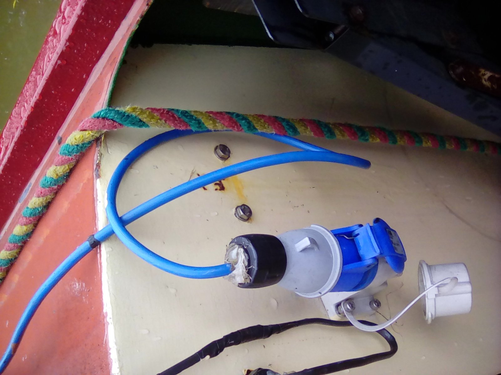
This is how I have my shore connection set up these days. IP44 plug and socket. Bulkhead male side facing upwards so when female shore lead is connected water is less likely to get in by gravity and pool around the pins. Extra water proofing with hot melt glue around the cable entry in to the socket. Shore cable arranged with a loop of wire to reduce the length along which water can collect and then run in to the cable entry gland. The boat is moored so that the whole thing is sheltered from the prevailing south westerlies where the majority of the rain comes. This combination seems to be good against all but several days of wind or sleet coming from the north east. A rare occurrence. The picture seems to be on its side for some random reason. Jen
-
What have you fettled for the boat today?
Jen-in-Wellies replied to Captain Fizz's topic in Boat Building & Maintenance
To cover up the holes in the steelwork from the previous bits of wood. It isn't a tradditional narrowboaty tgpe of bow, so doesn't have to look narrowboaty. -
As above, the IP44 rated sockets and plugs are not terribly waterproof. My boat is normally moored with the shore line connection sheltered from the prevailing westerly winds. If there is rain, or snow driving in from the north east for a few days it will get water in it and trip out the shore bollard RCD. I have tried it with the boat plug facing up and facing down and it makes no difference. Some people make a plastic shroud to shelter the connection from falling rain. A six pint rectangular plastic milk jug seems to be a good size for this. Not pretty, but works well. Basically, if you can give the IP44 connectors a bit of shelter then they will be OK. For a proper waterproof conne tion you need to go to a higher rating and a few boats have this. Most shore bollards have the IP44 outlets though with perhaps a bit of a shelter to divert water away. If you do get water in the connection the cheapest solution may be to turn your boat round! Jen
-
I have something similar made by Acme Whistles. http://www.acmewhistles.co.uk/xcart/product.php?productid=131&cat=5&page=1 Loud it is. Much more so than the weedy Halfords car horn. Easy to grab and let fly without searching around for the horn button. Mines a semitrad, so the switches are a distance from the steering position. Jen
-
Another vote for seeing if Bedazzled have something suitable, rather than cheapo ebay LED's. Did my boat out in their downlighters nearly ten years ago and they are still going strong. Had one go bad in that time and need replacing. The technology has moved on a lot in that time, but it shows they knew their stuff with voltage spike protection and individual fusing. No other connection with them than as a customer and all that stuff. Jen
-
The engine cover boards can get very warm when the engine is running. I've not seen plastic, or reinforced composite boards used, only buffalo and similar boards, or metal. Would worry about plastic warping or sagging. Less so with composite, but see if there is any information in the data sheets about maximum continuous temperature. Jen