Eeyore
-
Posts
1,246 -
Joined
-
Last visited
Content Type
Profiles
Forums
Events
Gallery
Blogs
Store
Everything posted by Eeyore
-

Beta Marine 38 Control Panel Identification and issues.
Eeyore replied to Jeff Naylor's topic in Boat Building & Maintenance
Alternator 2 D+ terminal -> warning lamp -> relay switch contact in (terminal 87) -> relay switch contact out (terminal 30) -> domestic battery positive. The coil of the relay is wired between ignition switch "on" position and battery negative (terminals 85 & 86) This ensures that all connections to the domestic alternator are associated with the domestic battery. -
Servicing Canaline 42 coolant - advice?
Eeyore replied to AndyE's topic in Boat Building & Maintenance
The anti freeze part doesn't die, its just the corrosion inhibitors that get used up. -
Odd Volvo Penta cooling water connections - any bright ideas?
Eeyore replied to cheesegas's topic in Boat Equipment
Why do you need to change from the method shown in those two photos? The spring clip stops the pipe from falling out. You can almost certainly turn down the threaded end of a barb fitting to emulate the volvo fitting. A lot easier to strip down and reassemble in the event of a blockage. Although I do appreciate the need to anchor any flexible hose to maintain alignment. -
Odd Volvo Penta cooling water connections - any bright ideas?
Eeyore replied to cheesegas's topic in Boat Equipment
The usual request for more pictures. -
Beta 38 (BV1505) stop solenoid replacement
Eeyore replied to Pete Morrison's topic in Boat Building & Maintenance
Energise to run generally have two coils. One high current “pull in” and one low current “hold in”. The pull in coil is only designed for momentarily operation, and should be controlled by a pull in timer unit. I say “should” because many are bodged from new to save the cost of the timer. The hold coil is just connected to the “on” position ((aux) on the key switch. No harm running over the terminals and case with a multimeter and putting the results on here. -
Beta 38 (BV1505) stop solenoid replacement
Eeyore replied to Pete Morrison's topic in Boat Building & Maintenance
The older engines had an energise to stop 2 wire solenoid, correct for marine applications (but not essential on canals). The new one is probably a 3 wire energise to run item, although it would require some rewiring for it to work. Essentially the engine would stop on the key. -
Or even the other way around 😎
-
I realised that. It's just a happy coincidence that your desired speed is commonly used for other applications, so components may be more competitively priced. Rexroth is of course now known as BoschRexroth. An interesting sounding project, I look forward to updates.
-
Firstly it would be useful to know how much power you could draw from the various take off points on the engine. It's not on the basic engine spec sheet. The alternator is just shy of 6kw, so given the usual inefficiencies you could be looking for upto 12kw from the pto. Starting an engine with that sort of load on a cold engine is a complete non starter, so some form of soft start/engine rev related control will be required. There will be plenty of kit out there that can maintain 1800 rpm (60hz on a 4 pole ac generator). Interestingly the speed can be maintained within a quite close range just by using a pressure relief valve between the flow and return. I found this when working on Rexroth systems under diesel railcars; the electronics were often disconnected due to conflicts between independent control systems allowing the relief valve to maintain in spec speed and ac frequency.
-
.
-
Where are you, perhaps someone could talk you though things whilst you made some notes.
-
I sure it was black, I was sent out to "rescue" the apprentice. Curiously he had wired it wrong without causing any short circuits!
-
Please take a photo of the offending plug and socket. There is a very remote possibility that you have the marine variant that uses one of the large terminals as battery negative.
-
Yanmar 1GM10 won't start - injector or pump?
Eeyore replied to cheesegas's topic in Boat Building & Maintenance
If you remove the front oil filler cap, by the injection pump, can you see much of the governor linkage? I'd be inclined to introduce some aerosol degreaser to remove any old and sticky oil residue, followed a bit later by some penetrating and easing fluid. Then maybe the fly weights and linkage would move as designed. -
I await the answer to "which way does it rotate". The last one I had with the wrong fan sprinkled bits of solder on the floor when removed, thats a bit hotter than normal.
-
Guilty as charged 😉 but the OP did say D+.
-
Thats an A127 type alternator, the black plastic shroud suggests that its a type supplied and fitted to many Ford vehicles. The voltage is abnormally high, suggesting that it is faulty. Cheapest and simplest fix is to change it. Let us know which way it rotates when viewed from the front; it may have the wrong handed fan fitted.
-
Would be nice to know how this was resolved. Everyone likes a happy ending.
-
Which I think equates to about 4.6 turns/threads engaged.
-
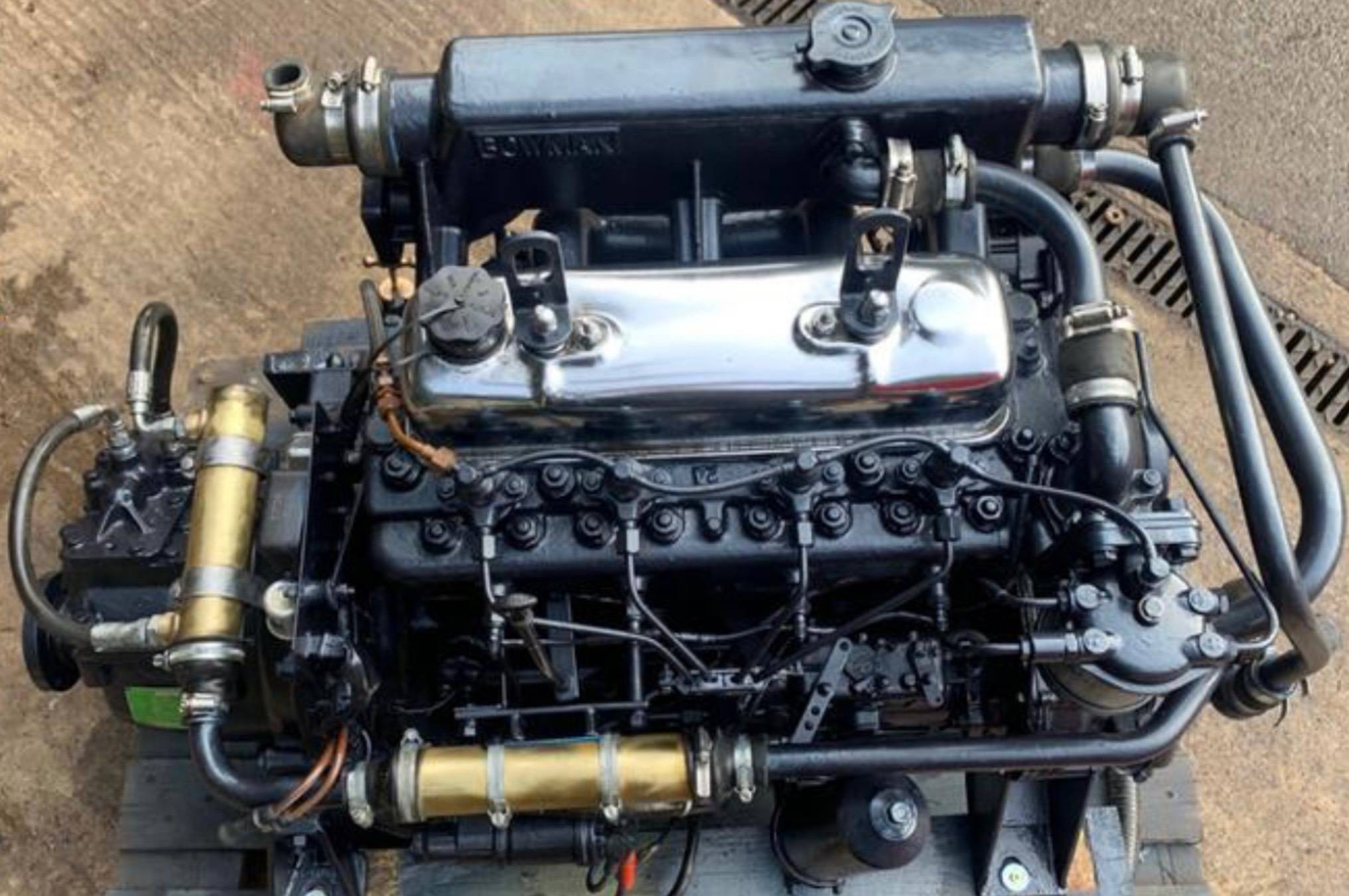
Thornycroft T154 62hp, or similar. Based on BMC 2.5.

-
Window removal technique / sealant?
Eeyore replied to Jaywire's topic in Boat Building & Maintenance
https://bestreviews.com/kitchen/tools/best-cut-resistant-gloves You'll need some of these. Not just for kitchens. -
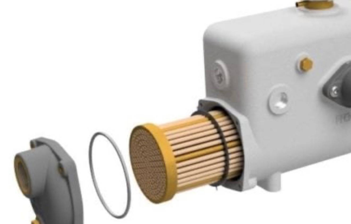
Beta 43 (v1903) Heat exchanger - oil cooler
Eeyore replied to rgriffiths's topic in Boat Building & Maintenance
This illustrates Tonys description; different cap fastening has no effect on the described sealing arrangement.
-
Engine stalling after an hour so run
Eeyore replied to GDJones's topic in Boat Building & Maintenance
A photo with a slightly wider angle view please. Need to see both connection. -
This post cannot be displayed because it is in a forum which requires at least 10 posts to view.
-
This post cannot be displayed because it is in a forum which requires at least 10 posts to view.