Eeyore
-
Posts
1,246 -
Joined
-
Last visited
Content Type
Profiles
Forums
Events
Gallery
Blogs
Store
Everything posted by Eeyore
-

Bad Vibrations (from an alternator)
Eeyore replied to spicemouse's topic in Boat Building & Maintenance
Looks like the "best" way it could fail; loose bolts could have given a much bigger headache. There are things in your photo that say this is not the first time that it's failed; no paint on the washers and what looks like a strengthening plate ( obscured by the dipstick tube). You'll need to remove the top nuts from the new engine mounts and jack it up in order to get the engine mounting beam out. The alternator mounting beam can probably be left attached as long as you disconnect and remove the alternator. Make sure that the beam sits equally on the engine mounting points before you fit the bolts otherwise the whole thing will twist as you tighten the bolts, which is very likely to have be a contributing factor in the failure. -
Bad Vibrations (from an alternator)
Eeyore replied to spicemouse's topic in Boat Building & Maintenance
I will have to go with Loddon on this. The mounting arm is attached to the main engine mounting beam; its this beam that appears loose on the engine. You may need to remove the mounting arm to gain access to the set bolts attaching the front of the main engine mounting beam to the engine. Shut it down and try rocking the front of the engine whilst checking for movement as indicated by the arrows in Loddons post. -
Laidong LL480QE engine, but they seem to be manufactured by several companies in different configuration. As per the part number https://www.aliexpress.com/item/1005002056450877.html
-
Argg! Who has successfully fitted fibreglass porthole liners?
Eeyore replied to Ally's topic in Boat Building & Maintenance
The instructions for model kits made of fibre glass often suggest scrubbing with a soap ( not detergent ) solution prior to gluing. Detergents contain oils that inhibit many glues. -
Worcester, Droitwich, Sawley (Long Eaton), Port Avon (Keynsham), Bristol, Bradford upon Avon, Bath, Gloucester, Devises (Bus to Swindon or Pewsey), Otherton (Penkridge), Aston (Stone), Great Haywood (Bus to Stafford or Rugeley)
-
The same applies to your phone battery, especially if you use a slower/ lower current charger. I used to charge my iPhone using the 2.1 amp charger that came with the iPad, but noticed that battery health percentage was dropping quite quickly. I now only charge the phone on a 1 amp charger and the battery health percentage drops much more slowly.
-
Do you have a relay in the wiring between the engine and control panel? A picture would be useful if you do. It just hangs off the side of the loom, maybe a foot or two from the engine if memory serves.
-
Do you have a “slave” relay for the stop solenoid? Often found in the wiring partway between the engine and control panel on earlier Barrus engines.
-
The Delta box has a fine spline on the input shaft, inspect carefully before refitting. Hopefully yours will be ok, but they do have a reputation for wear.
-
I suspect that the initial problem lies with the phrase “charged and ready to fit” which often crops up in an automotive context. The two new batteries would have undoubtedly benefited from a full charge before fitting. Whether they have been fitted correctly is a different matter of course.
-
But your batteries would charge with the engine running anyway. Or have I missed something?
-
Interesting, I remember the "clunk" as a healthy sign. The cone clutches have to displace the oil before they can fully engage. A more viscous oil takes longer to displace slowing down engagement which can lead to excessive slip, heating and wear. About a hundred years ago Rolls Royce injected caster oil into the cone clutches used on their vehicles to force a slip and reduce the "clunk". (a hundred years ago when father was just a twinkle in grandfathers eye)
-
Element for fuel filter Vetus 330VTEB
Eeyore replied to umpire111's topic in Boat Building & Maintenance
Not necessarily, it's marked as ISO10088 compliant; but probably only if the metal heat shield is fitted (the bowl shaped piece of metal in the OPs picture). -
Element for fuel filter Vetus 330VTEB
Eeyore replied to umpire111's topic in Boat Building & Maintenance
Yes, all the materials to do the job for less than the price of a Vetus filter; and that includes the possibility of having to buy the metric threaded head as well. Looks like the job will pay for its self in a fairly short time. -
It's quite common for engines to come to rest in the same position when they stop. This means that the starter tends to engage on the same part of the ring gear every time you start the engine. Over time the normal wear and tear is localised and can eventually lead to damage on the leading edge of the pinion and the starter facing side of the ring gear. Failure to engage will be infrequent at first, but the damage then tends to accelerate, leading to a total failure to engage. Turning the engine a few degrees by hand presents an undamaged section of ring gear to the (now newer) starter pinion.
-
Element for fuel filter Vetus 330VTEB
Eeyore replied to umpire111's topic in Boat Building & Maintenance
And cheaper from https://www.midlandchandlers.co.uk/products/cav-agglomerator-5836b900-ea-125 well there's a surprise ? -
Element for fuel filter Vetus 330VTEB
Eeyore replied to umpire111's topic in Boat Building & Maintenance
M14 threaded head. https://www.ssldieselparts.co.uk/single-filter-head-type-p-701.html -
Element for fuel filter Vetus 330VTEB
Eeyore replied to umpire111's topic in Boat Building & Maintenance
https://www.asap-supplies.com/products/drive-force-cav-fuel-filter-water-separator-45-lph-alloy-bowl-302006 You will need to change the fittings on the fuel hoses to suit the 1/2" UNF threads. They may be available elsewhere with M14 threads, which will be an easier install if the existing unit has M14. -
Element for fuel filter Vetus 330VTEB
Eeyore replied to umpire111's topic in Boat Building & Maintenance
The Vetus manual https://www.vetus.com/media/magentominds/sasdocument/20190604114543_0.pdf recommends to change the filter annually or every 200 engine hours; which should help in deciding whether it's economical to retain it or fit a cheaper to service alternative. Note that the manual shows the connection ports as M16x1.5 thread, whilst the specification on the web page shows some variants as M14x1.5. Not easy to tell which it is from the OPs original photo. -
Element for fuel filter Vetus 330VTEB
Eeyore replied to umpire111's topic in Boat Building & Maintenance
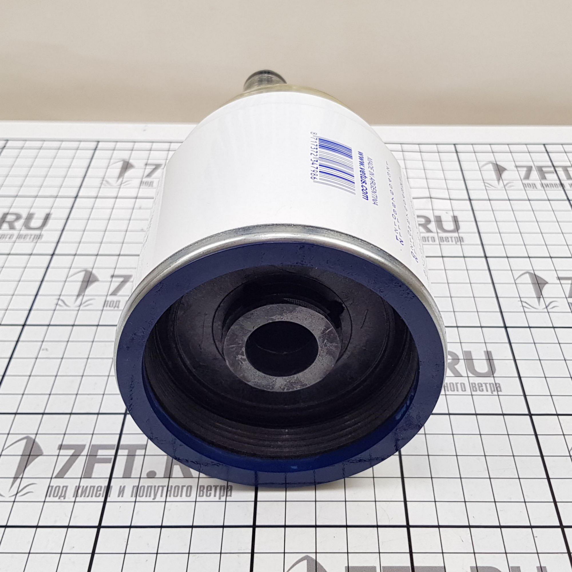
Best pictures I could find online, that's a very large diameter thread. Looks like the bowl is integral to the filter.
-
Element for fuel filter Vetus 330VTEB
Eeyore replied to umpire111's topic in Boat Building & Maintenance
Do you have a picture of the filter please? -
https://www.durite.co.uk/s/c/switches-and-indicators/ignition-switches/5-position-switch-26mm-diameter-panel-hole or https://hc-cargo.co.uk/catalog/p/180044--ignition-switch This one will do the job, it has an extra terminal (58) that can be ignored in this application. (The extra terminal works with Vetus applications)
-
A picture of your panel, front and back, would be useful. The job might be "interesting" if the wiring was altered to suit the current occupant of the hole in question.
-
Engineering officer: How long will it take? Tiffy: About 2 hours. Engineering officer: You've got 10 minutes before we sink. Tiffy: Ok, I know a bodge that'll work, if I can get hold of a sanding block in the next 10 minutes. Beyond that I'll be sticking to established engineering methods; "v" belt drives have been around for about 100 years, so we must have been doing something right all this time.