Rincewind
-
Posts
109 -
Joined
-
Last visited
Content Type
Profiles
Forums
Events
Gallery
Blogs
Store
Everything posted by Rincewind
-
I have made the assumption – from the drawing – that contacts #17 & #50 are connected together either internally or externally when the switch is in position ❷. You may wish to check if that is indeed the case by doing a continuity test with a multimeter. Isolate the power from the switch and hold the switch in position ❷ while you test for continuity across #17 & #50 (at the anode end of the diode). You may need to grow another arm & hand while you do this! So if you intend to use the original ignition switch and my assumptions are confirmed then the answer is Yes, you will still need to incorporate the diode. Be aware that the maximum current that this particular diode can safely carry is 6 amps (See the IN5404 Datasheet), and as the current demanded by the glow plugs will almost certainly exceed 6 amps, a suitable relay should be used – if one is not already installed. Judging by the photographs of the switch, the size of the cables would suggest that you do have a relay somewhere in the depths of your engine room.
-
An unusual & confusing schematic diagram as far as the switch is concerned but I think I may have sussed it. All the connections I refer to are implied and need clarifying by tracing the wires through the loom to their respective components – or otherwise as the case may be! I assume thus:- on the drawing- Switch Connection # 30 Positive feed wire from battery to ignition switch Switch Connection # 58 Not Connected Switch Connection # 15/64 to Instruments etc. Switch Connection # 19 Glow Plugs (via Relay?) Switch Connection # 17 Starter Motor Solenoid (via Relay?) Switch Connection # 50 Glow Plugs, via Blocking Diode D1 to #19 cable Switch Positions:- Position P · Auxiliary position to supply power to equipment via # 58 when Engine is OFF (# 58 Not Connected) Position ⓿ All OFF Position ❶ Normal Running Mode · Connects # 30 to # 15/54 (Instruments etc.) Position ❷ Pre Heat Position · Connects # 30 to # 15/54 (Instruments) & · Connects # 30 to # 19 (Glow Plugs) Position ❸ Starter Motor Engagement · Connects # 30 to # 15/54 Instruments & · Connects # 30 to # 17 Starter Motor Solenoid & · Connects #30 to #50 Glow Plugs via Blocking Diode D1 Use of the Blocking Diode D1 prevents power being applied to connection #17 when the switch is in position ❷ However during Starter Motor engagement (when power to #19 is denied) it allows power to be continuously supplied to the Glow Plugs. https://datasheetspdf.com/pdf/1259962/Multicomp/1N5404/1 For those not familiar with diode symbols, the arrowhead (Anode) indicates the direction of flow whilst the vertical bar (Cathode) symbolises flow that is blocked. The Cathode connection is indicated by a ring (white, in this instance) on one end of the component. It is important to connect it the right way round, as in the drawing. I suspect that the ignition switch was designed for a different application and this arrangement was a “work around” for these boats / engines.
-
morso 1410 top plate replacement
Rincewind replied to nairb123's topic in Boat Building & Maintenance
New Spares are available for this stove from chandlers. (Somewhere in the “Midlands”!) The top plate is secured in place by four 6mm setscrews which screw into threaded holes in the top plate. It is unlikely after all those years in service that they will unscrew and you may have to resort to cutting the setscrews through with an angle grinder fitted with a cutting disc accessed from inside the stove. (Between the top plate and the lugs that are cast to the back and front plates of the stove) It can be done, carefully, as I can testify! New collars are also available held in place in a similar fashion by two screws and clips. The Top Plate is supplied with sealing cord fitted in place ready for assembly and, if I remember correctly, screws were also supplied. Bear in mind that these four screws and another four at the bottom plate is all that holds the stove together so you are advised to use a strap (or two) - that you can pre-tension, around the four sides of the stove prior to removing the top plate to prevent it “all falling apart”. If removal of the top plate reveals further damage, what have you lost? Best of Luck -
Before you go to the trouble of removing the head, here is another method of Top Hat removal you may wish to consider. If you measure the OD of a new Top Hat (the body, not the brim) you will find it is 17.44mm diameter with an internal diameter of 14.54mm. This enables you to use a 5/8 UNF tap to cut a thread into the old Top Hat without fear of cutting into the cylinder head itself as the OD of the tap is less than the OD of the Top Hat. e.g. A 5/8 UNF tap has a diameter of 15.8mm and a root diameter of approx. 14.5mm, (and as a bonus, the recommended tap drill size is 14.5mm!) – (ensure the tap is aligned correctly when cutting the thread). You may find, as you do so, that the force required to cut a thread into the Top Hat is enough to break the hold of both the carbon deposits and the copper washer underneath the brim and, if you are lucky, then the Top Hat will come away attached to the tap. If not, then a suitable bolt screwed tightly into the freshly formed thread along with steady uniform extraction force applied to the underside of the bolt head will be enough to remove the Top Hat. I do not advocate the use of a slide hammer on this potentially fragile thread as the shock forces induced will most likely fracture and strip the threads. Fill the flutes of the tap with grease to prevent swarf from falling into the combustion chamber.
-
No reason at all and no need for trig. If you see any movement of the readout you have wear. Question is will the DTI plunger reach the shaft? you could use an extension I suppose if you have one. Never worked out the capacity of the accumulated drips! - I will take your word for it! My bilge pump discharges it!
-
This is a fundamental mistake, but understandable. It is desirable, and indeed, essential for the gland to drip water. (Based on years of repacking uncountable numbers of pumps and valves for a living) If the gland is tightened to the point where water (or grease) cannot penetrate through the interface between shaft & packing then cooling and lubrication of the gland/seal is being prevented. The result will be uncontrolled friction, the heat from which will burn the packing and induce a hard glaze to the material that cannot be recovered. The elasticity of the packing, where it matters most, is lost, and eventually excessive water will leak through the gland which will then encourage the operator / boat owner to tighten the gland even more. This will lead to more friction between the shaft and packing to the point where both components wear excessively with catastrophic consequences. When the packing goes hard it will then become an abrasive and wear away metal from the shaft, the steel particles will lodge in the packing (that is now becoming an ever increasingly abrasive material) escalating damage to the shaft. Pictures from other contributor's to this thread illustrate what can happen. Water resistant grease is the lubricant to use and the drips of water, if allowed to pass through the gland, will both cool the gland and carry away any generated heat. The amount of water that drips when under way – or rate of drip – should be approx. one or two drips per minute or thereabouts depending on the condition of the components. If the stuffing box gets hot increase the drip rate. If the components are in good condition then the rate of drip can be controlled with judicial adjustment of the gland follower nuts. Light tightening of the gland nuts is the key word so that you don’t overtighten the packing and the use of lock nuts to prevent backing off due to vibration is recommended. Management of the leakage is what is required. Place a suitable container underneath the stuffing box gland to catch the drips and install an automatic bilge pump into that container to discharge the collected water overboard. If you do not wish the gland to drip water overnight or whenever the boat is stationary for long periods then pump some water resistant grease (such as Ramanol White Lithium Grease - other brands are available ) into the gland/bearing with a grease gun which will displace the water and effect a seal in the voids. If, as the OP states, water is pouring out, then a new shaft may be the only remedy together with a new approach to gland maintenance. It is unlikely that the stuffing box will need to be replaced, it does not come into contact with any moving parts. Just before lockdown I used the dry-dock at Ellesmere to black the bottom of my boat and took the opportunity to remove the prop shaft for inspection. It showed no sign of wear and was as good as the day I installed it more than twenty years ago. I repacked the gland with new packing as a matter of course even though the old packing was still supple. The moral here is get it right and you will have no problems in the future. But have they been fitted correctly? If three turns of packing are used these should be inserted with the ends of each turn 120˚ apart with the final turn having the ends at the 6 o’clock position. e.g. 10 o'clock, 2 o'clock & 6 o'clock. If the turns of packing are not cut to the correct length (i.e. short at one end!) and the ends are all in line then……!!! I agree with BEngo but if the hole is not perpendicular you could use a Telescopic bore gauge tool such as these for hard to get to small internal measurements. https://measuringtoolscentre.com/product/telescopic-gauge/ Several measurements between the Stuffing box wall and the shaft at different depths should give you an indication of wear.
-
I realize that you would prefer to adjust the built in indicator but if that is not possible and if you are comfortable with playing with electronics, you could try one of these sensors that you position on the outside of the container at any height of your choice. https://www.ebay.co.uk/itm/363269404850?hash=item54948b38b2:g:SzQAAOSwFChgB~FN Just three wires to connect, Positive, Negative & output. Use the output to drive a remote LED indicator via a suitable resistor. If you can see the sensor when the cassette is in position you do not even need the output - there is a LED built in on the sensor body that illuminates when the water level is detected. The sensor can slide out of its holder when you want to remove the cassette which means that the sensor can be permanently wired. I have tried one on a plastic container with 4mm thick walls and I can confirm that it can detect the liquid inside but I have never tried using one on a toilet cassette so the only way to find out if it would work is to take a punt for a few squid and "suck it and see"!
-
Just Measured a spare bolt I have for my BMC 1.5D Nominal Diam = 0.625" (5/8") TPI = 16 (55 degree Whitworth thread form)
-
I agree, The signs should be 30 or 40 metres long and 2 metres high so we old folk can read them as we trundle along. It will also keep CRT staff busy for a few years replacing the existing short signs (Providing there is enough blue paint in the country). Could we have a separate 40 metre long sign in brail as well?
-
Thanks Chewy, I wont be going down a complete harness route ! Time is not a factor, I can connect it by using individual female receptacles in the plug (that's how I tested it when it arrived to make sure it was not faulty) but that would not be waterproof or neat and tidy. Not that it needs to be waterproof as it is located in the engine bay, but once I get the bit between my teeth I cant let go! Its turned into more of a challenge now to identify it and source it!
-
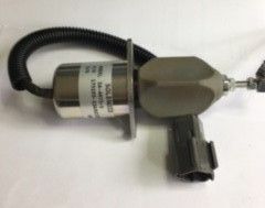
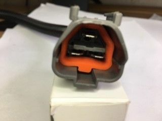
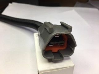
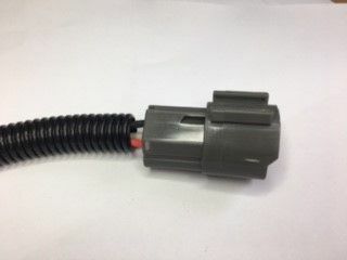
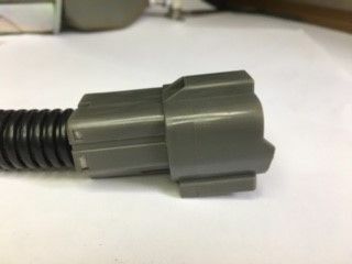
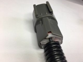
Can anyone help me identify the manufacturer of this 3 pin / 6mm spade plug (and socket?) please - and more importantly, a (UK?) supplier. I recently bought a new diesel on/off solenoid (sold as a replacement part for Kubota and Volvo tractors etc.) and it came with a fitted plug. When I ordered it I had intended to cut off the plug and replace it with one of my own which I keep a small stock of, however on arrival it seems, on the face of it, that this is a pretty decent waterproof connector and could be pressed into service if only I could purchase the mating female part. It has no identification marks anywhere, not even any manufacturing code numbers etc. It is similar in style / appearance to a connector made by Deutsch but this particular plug is not within their ranges. I have searched online with companies such as 12 volt planet, Altechautomotive, CPC / Farnell, RS, Mouser, Digikey some other smaller automotive companies and even eBay without success. I did find an American eBay seller with a two pin socket for sale but they would not ship to the UK so I did not pursue the possibility of a 3 pin socket with them. Any help would be appreciated otherwise it’s …..Off with its head!

-
Not only is It quite acceptable to wait for another boat with an experienced crew to share the lock with you, you will be saving water too. Have Fun
-
You are correct. Glands with stuffing boxes are designed to drip, the water not only helps cool the assembly it keeps the packing moist and disperses heat. Tightening the gland to the point where water is prevented from dripping will lead to the packing drying out which in turn will lead to greater friction between the (now hard) packing and the rotating shaft. That friction will wear away both the shaft and the packing leaving grooves in the shaft and shredding the packing. This leads to even more increased dripping and then the gland is tightened again and... so on and so on. New prop shaft please... The trick is regulating the drip to an acceptable level You should grease the stuffing box each day when travelling. Do it after you have stopped for the day and the grease will act as a stopper overnight. I have a hard plastic container under my stern gland to catch the water and my auto bilge pump is situated in the container. My engine bay is completely dry...always!
-
Sludge... Without going too deep into this - - is all to do with the settlement of suspended solids. It has nothing to do with evaporation of water but separation of water and solids by gravity! And along with the (natural) bacteria and heat - if present, sludge that contains a high proportion of "food - i.e. human waste" for the bugs to eat provides the near perfect conditions for anaerobic digestion. The dear little darlings like a warm environment and become more active when the temperature of the sludge rises therefore the climate can have an influence on the natural process.
-
I came across this very scenario that Tony describes, vertical baffles in a skin tank that created an air lock at the top of the tank and led to overheating. The only way to alleviate the problem was to drill & tap the tank above the air lock in order to vent it with small bore pipework to the header tank.
-
You can bet your bottom Dollar that Sods Law comes into play:- two hours into that "quieter job" and you will have to admit to yourself that an ear piercing power tool is the only way to proceed... no matter how hard you plan in advance! Hardly the time to cast off, travel for a couple of miles and leave your land based car / van laden tool chest behind. Better to find a mooring / DIY boat yard that has the facilities you require (including Loo's, - often overlooked when selecting a site) even if that involves more travel / cost than you planned for. You will get the fit out done more quickly in my view.
-
I have used them online and have received an confirmation email for my order, so I suggest you check your junk mail folder. However I am a 30 minute drive away from them so no longer order online and they have a "walk in" shop, - cuts down on the supply delay - I am often impatient!. Sorry, I do not have the "Leyland light weight parts book" you speak of so I cannot comment, but it would be interesting to view!
-
I was in Charnleys buying some BMC parts just this afternoon and was assured by the gentleman who served me that if the parts I purchased were to prove surplus to requirements that I could return them for a refund at any time (provided that they were unused and resalable). Its not often these days that you get that kind of customer service so I can highly recommend this company - and their very helpful & friendly staff. (For anyone else looking to purchase a complete Timing Chain Tensioner, and I know they are thin on the ground at the moment, they are due in at mid April I was informed, but due to global supply problems, "watch this space" )
-
That is a large amount of oil to lose in such a short time. If the engine is in a confined space and you cannot visually see the oil escaping when the engine is running try cleaning the engine and surrounding area thoroughly and then lay white paper towel under the areas you suspect are leaking (and areas you don't suspect!). Then run the engine for a short period. You should then be able to pinpoint the source of any leaks. Try this link for an alternative supplier, but I would phone them first before ordering to ensure its the correct part. Tappet Cover Gasket
-
Whether you do or do not replace your batteries, I really, really, really do suggest that you re-route that blue wire (connected to the negative terminal?) away from those positive terminals, at the moment it is a potential electrical short / fire hazard.
-
wernt on tinternet, twas taken last July at Gas St where we stopped off at waterin ole!
-
They tried that idea in Brum, mate including elf & Safety face mask- but it kept wandering off the towpath!
-
Train them to hunt fishermen, plenty of em about
-
Beta Marine control panel problem
Rincewind replied to WYVERN's topic in Boat Building & Maintenance
"if it aint broke don't fix it" Could not agree more! Sorry for the long post, thought you may be unfamiliar with connectors! Spring clips were used on some old connectors, but these days they are usually an interference fit, with reliance on the the natural spring (reluctance) in the female part making contact with the male part. A bit like real life really!