Eeyore
-
Posts
1,246 -
Joined
-
Last visited
Content Type
Profiles
Forums
Events
Gallery
Blogs
Store
Everything posted by Eeyore
-

Replacing Engine mounts Barrus Shire 45
Eeyore replied to TeeELL's topic in Boat Building & Maintenance
The position, as found, of the lower nuts is fine providing that the engine beds are perfectly aligned; which is unlikely. Only one lower nut needs to be adjusted on your particular installation to achieve the best weight distribution; as it will most likely rock slightly on one diagonal. The choice should be based on your ability to reach it with a spanner when making routine checks. The failure of the one, top left in your photo, seems to be due to over heating. The failure may also be counter intuitive; as the mount on the rocking diagonal will move far more than those carrying most of the weight, similar to the excess movement suffered by the sidewall of an under inflated tyre. -
The lack of a filter between the tank and pump will be an issue, you'll probably get the same problem with a new pump; and maybe the heater fuel pump as well. Time to get down the hole and have a look. Something like this has a filter fitted (under the bayonet fitting cap at one end), might be the cheaper option if you can't find a filter fitted elsewhere. https://www.ebay.co.uk/itm/173328613060?hash=item285b30bec4:g:KsYAAOSwK9lfae06&amdata=enc%3AAQAIAAAAwADP0N9Bz77q13BDaGAgz9teEAeqspFB05iw%2F7YdNVwZ0rVCOvySsKeJMlyk9fz7Q2P3T6E36Sr4ANZGNPHMZp3RfRB115ZPkZGaGg%2F02o32ukrxls5jb6IYk0f5lqMGapR05oyy%2FwUQON5rP46TnJEfyZHKbKN5Dpoe3FVv%2FKtyBsq1C%2BaryPlP5ZVnBDo5F2abEKxr7rbKgZtLm0FFXe8DzuFiuCjCYMVSpgkToQMAHwVLwrD6zSsON44l15kpfw%3D%3D|tkp%3ABk9SR6bt7ZSHYg
-
A friend recently cut open the failed genuine pump on my spare (now sold) 3TNV82A. Its was difficult to imagine it being made any cheaper than it appeared!
-
The answer to the lack of electric boat charging points?
Eeyore replied to a topic in General Boating
Already been tried, Kidderminster area I think. Long time ago. -
Help understanding why paint failed this way
Eeyore replied to JaimeManero's topic in Boat Building & Maintenance
Preparation will have also played a significant part in the failure, such as needle gunning, wire brushing and thoroughly degreasing the surface prior to applying rust converter. The weather, specifically the moisture content of the atmosphere, and the temperature of the steel in bright sunlight. There also seems to be an undercoat missing from your scheme. -
Engine mount to engine bearer torque settings
Eeyore replied to PCSB's topic in Boat Building & Maintenance
Oh go on then, what about yield point tightening (if you can afford the kit). It may not be an exclusively Bristolian thing, but it definitely fits very nicely, in its various forms, between the syllables of longer words. Dia*bolical is a personal favourite. -
Engine mount to engine bearer torque settings
Eeyore replied to PCSB's topic in Boat Building & Maintenance
The “F” is a commonly used abbreviation for the “universal adjective”. 😎 We was taught proper in the RN. -
@karanight Halfords say these have 35 square millimetres cross sectional area of copper, you will often find these figures moulded into the insulation of the cables. Should be fine.
-
Same earth/ground as the circuit it’s protecting , can’t see it working correctly otherwise. An email to the manufacturers technical department is probably the way to go.
-
Photo from above and below might be handy.
-
The mains charger has been off for most of the week, and the solar seems to be in "sulk" mode at the moment; so plenty on Mikes "to do" list at the moment. The alternator voltage was climbing steadily when running, even though the Sterling alternator controller didn't seem to be working - some but not all the expected lights showing. I would say that several people have been in there over the years, probably looks worse than it is because some of the cable ties will have been removed for access.
-
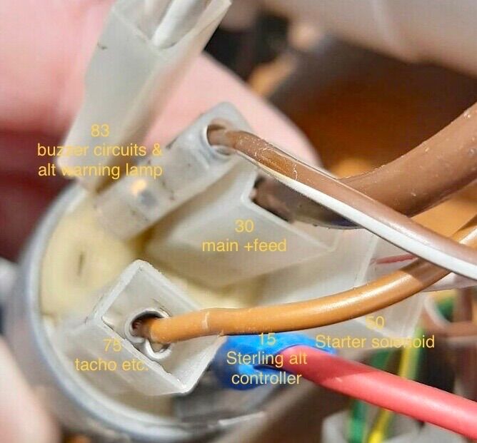
Terminal 83 is a bit of a red herring, turning out to be a normally closed contact which is open in the on and start positions of the key switch. It has been like this since @Mike H took ownership, and its easy to see why it could be taken as a dodgy switch; which it might also be given the odd things happening when the key was waggled around. So as wired (see photo) the off position gave warning lamps and buzzer, the on position gave tacho/hour meter and sterling alt controller; but not consistently due to the waggle effect. Starting was unaffected as this engine has an energise to stop solenoid, and "normal" running was undertaken with the key switch in the off position so that the alternator would charge. The key would then be turned to the on position to give power to the stop button (same feed as tacho), and left in this "quiet" position whilst the engine was shut down. The new Barrus switch of course exhibited the same symptoms, whilst the Durite switch lacked terminal 83 that was believed to be necessary. A small clue was missed early on when Mike queried the piggy back terminal on the red wire, which had clearly had something attached in the past. Four wires requiring a switched feed, two with piggy back connections - hmm I wonder. The Durite switch has been installed because Mike had already crimped a new fitting on the main feed wire for the larger spade on terminal 30 (not enough wire to change it back); and I have to agree, it just felt much smoother in operation. The four wires in their piggy backed pairs now reside on terminals 15 and 15a, and all appears well. At this point we adopted that proven working method of quitting whilst ahead, the coffee and good biscuits making an appearance shortly afterwards.

-
Same advice as @Tracy D'arth really, just can’t keep up with all the changes nowadays. @Withywindle a few picture showing any obvious differences would of course be most appreciated.
-
Stafford Riverway Link/Stafford Branch
Eeyore replied to CourtAboveTheCut's topic in History & Heritage
The remains of what you refer to as a wall are what remains of the towpath bridge over the junction. -
It has to be said that neither of the wiring diagrams appears to reflect the reality as shown in the photos as regards the ignition switch wiring; terminals or colour coding. The "detailed" drawing shows what is basically the simplest wiring for a standard switch (given the accessories fitted), and the Barrus drawing is in no way applicable to this setup, being a current production item with twin alternators and timer relay (and certainly not the same switch). I've asked for a list/table of the wiring terminals/colour/destination, because without that its impossible to see what has been done to the wiring to create this "fault". I'm guessing the boat is at the marina?
-
The forum software keeps combining my posts, not sure if a notification is sent each time, ho hum. Terminal 75 is usually radio/cigar lighter Terminal 83 is the common contact on normally closed or changeover switches. Probably worth checking for voltage on all the wires when disconnected. The reason for Barrus choosing such a switch may never be known, but I find myself drawn to the words "bargain bin" 😗
-
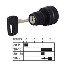
Time to reverse engineer this? No obvious reason, as yet, not to use a standard switch. Can we have the terminal number/colour/function(destination) for the wires as connected to the Barrus switch. A picture of the alternator terminals and the Sterling split charge gizmo terminals would be handy. Here is the contact diagram for the Durite switch showing internal connections for each key position. You should, with a test lamp or multimeter be able to draw the equivalent for the BS switch, just clip one test lead to "30" and work through the key positions, checking to all of the other terminals in each key position.
-
Thanks, but I was wanting to see the terminal numbers side by side.
-
Pictures of the original and supposed equivalents side by side might be useful.
-
Curious, I can only find references to the valve clearance being 7 to 9 thou on that engine. Run the engine with the rocker cover off and try sliding a 3 thou feeler between each rocker and valve in turn to see if the noise reduces.
-
Filter elements for the F2 housing are rarer than rocking horse droppings. Owners and operators of 1950s Railcars (DMUs) on heritage lines have a thirty plus year lead on you when it comes to finding them; but please share if you find any 😎. Many have converted to the still common "CAV 296" type, and some to spin on types. I have seen 296 elements in these housings, big mistake as the incompatible designs simply allows unfiltered fuel to the injection pump.
-
No gas on board, on a budget! It's no more that about 8Kva, and definitely not a balanced load, the neutral current will be all over the place. The "race" did occur to me whilst typing, but easy enough to try. I think the piggy bank will need raiding for a new 4 pole switch😕
-
Sorry, not enough detail in my original post. Its all 3 phase with a 3 pole change over switch, common neutral. I'm thinking of passing this one on, happy to learn, but not to put my name to it. 😱
-
I'm investigating the possibility of adding a grounding relay to an (as found) existing system and wondering if there is a preferred method? One on board source and a shore supply fitted, the on board source has a neutral to earth bond and is bonded to the steelwork. The shore supply earth is also bonded to the steelwork. Has worked up to the point the shore side bollard was upgraded with earth leakage protection; better late than never I suppose. Not enough poles on the changeover switch to switch the earth connection, and limited budget. Option 1. On board source neutral and earth connected to the normally closed contacts of the relay, i.e defaults to bonded. Coil of relay energised by shore supply when change over switch in shore position, opening the contacts and removing the bond. Option 2. On board source neutral and earth connected to the normally open contacts of the relay, i.e defaults to not bonded. Coil of relay energised by on board source when change over switch in on board position, closing the contacts and making the bond. Some of the web search results seemed to imply option 1, but nothing definite. There is probably something obvious on the safety side of things re failure modes that should inform the decision? Be kind😎
-
Oil dipstick level / engine manual
Eeyore replied to Mike Barber's topic in Boat Building & Maintenance
Thats a very old engine, possibly a Kubota V12** (V = 4 cylinder, 12 = appox 1200 cc, **= engine series). I think the engine might be a V1202, long since replaced by the current 05 series engine. You'll find it stamped into the engine casting. HE = Heat exchanger. KC = Keel cooler. Just a different exhaust manifold an extra pump and a bit of plumbing. https://www.peachment.co.uk/discontinued/4-110h-4-110he/ The main issue regarding servicing is the oil filter, with the 02 series engine using a 3/4" UN thread and the 05 series engine using a M20 thread. Typical engine number locations for Kubota engines. https://global.engine.kubota.co.jp/en/support/serialnumber/index.html