jonesthenuke
-
Posts
931 -
Joined
-
Last visited
Content Type
Profiles
Forums
Events
Gallery
Blogs
Store
Everything posted by jonesthenuke
-
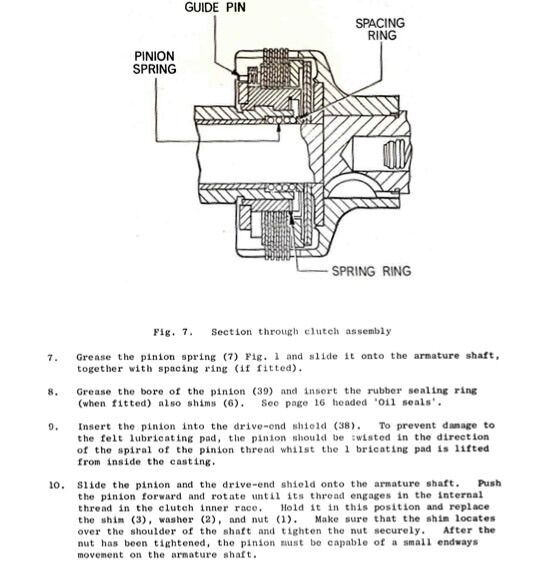
From CAV manual 2571/2

-
Yes they do.
-
This is from the Gardner LW engine manual and gives cable sizes (in imperial units). I have measured the starting current of our 3LW with 12 V starter. IIRC it was 300-400 A ELECTRICAL EQUIPMENT Voltage.-24 volt (min.) equipment is recommended for all vertical and horizontal LW Type engines. Battery.--The size of battery wil usually be determined by lamp load, but for engine starting only the recommended capacity is 100 ampere-hours at 10-hour rate. Cable Sizes. The minimum sizes of cable should be not less than thefollowing:- Battery to Starter 61/044in. 10ft.(3,048mm.)max. Alternator to Control Board 226/-012in.5ft. (4,572mm.)max. Field Switch to starter. 14/-012in. Control Board to Battery 266/-012 in.
-
 Possibly a sensible approach in London, say within the M25?
 -
You could do the Droitwich canal as an option?
-
As well as the BCNS the Bradley canal restoration society welcomes volunteers. Workdays have been monthly during the winter, but I have yet to see a programme for this winter.
-
Any update on this? Just curious.
-
Stop at Caunsall on the Staffs and Worcs and go to the Anchor pub. Best cobs ever and at bargain prices. The pub is about 500m from the canal. Stop at the road bridge north of the pub and walk along the road.
-
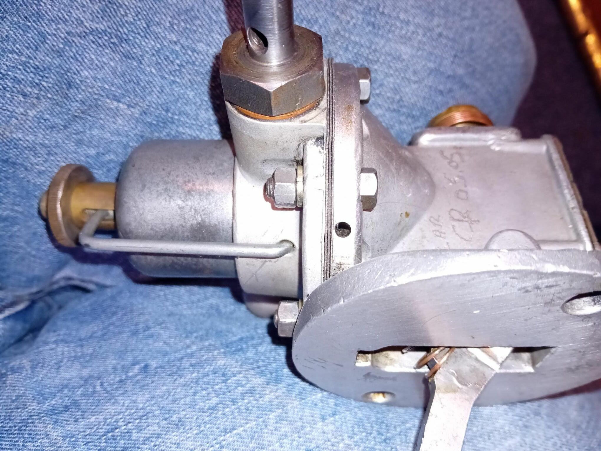
FYI two drain holes as in centre of this image
-
How much fuel around the lift pump and are you certain it is fuel and not oil? Some lube oil will get onto the top of the diaphragm and the upper pump body has drainage holes to clear this. in the past i thought i had a leaking diaphragm but in the end concluded it was oil.
-
For clarity, I assume you mean you are operating the priming lever on the lift pump or are you operating the levers on the injection pump? Whilst a leak on the fuel line or pump sounds likely,and is worth checking I would have expected the engine to start on the fuel left in the injection pump. How is your fuel supply arranged? Is the tank lower than the engine and thus potentially fuel is flowing back to the tank if the lift pump valves are not sealing? Perhaps some photos would help.
-
Maintenance of Epoxy coated hull
jonesthenuke replied to jonesthenuke's topic in Boat Building & Maintenance
I had forgotten about this post and should have updated earlier. In the end I did not use a Dacrylate coating but changed to Hempel Hempadur from Limekiln Chandlers. After four years it still looks fine. -
I struggled to find the bleed screw on our boat. It was in a cupboard, in a small gap next to the inverter, behind wooden panelling and covered in spray foam. I was quite pleased when I found it!
-
I assumed he has had it coated with 2 pack, in his comment he said "I've not had the 2 pac stuff before last time - how often would you reckon to get it redone? " Thus blasting will not be required.
-
We had our boat blasted and 2 packed with Dacrylate. About 4 years later we had it dry docked for anodes, some painting and to check the 2 pack coating which was very good. I gave it another 2 coats of 2 pack , this time with Hempel Hempadur. Hempel recommended pressure washing plus lightly abrading the surface with a wire brush in an angle grinder in order to provide an adequate key. You may need to follow the same process, the wire brushing is not hard work but adds about a day to the process as the large area means it takes a lot of time.
-
The images of screwfix etc pipe and pipe fittings are to my mind not suitable as they are domestic drain fittings and are designed to operate unpressurised. The other pictures show Durapipe and similar industrial fittings/pipe which are designed for pressurised systems (some ranges are 10Bar rated). As others have said use swept bends, or fit Tees in place of elbows with screwed access plugs on the unused port to allow rodding through in the event of blockages. This will cost more, but consider the consequences of pipe failure!
-
The master switch could well be the problem if the SmartBank connects downstream from it (and it should). Either measure the voltage across the master switch or connect across it, e.g with a jump lead if you have a set (only need one lead)
-
A volt drop of 5V would easily initiate the error code, I suspect it comes on at a fraction of a volt. Similarly 0.6 Ohms is too much. Whilst you measured with the engine off, I assume the batteries were still connected to the relay? If so an ohmmeter may well give an erroneous reading. I suggest you disconnect one of the large wires from the relay and then measure the resistance across the contacts. If needs be, operate the emergency function on the Smartguage to close the relay. You should take into account the resistance of the meter leads (take a measurement with the probes connected together) as the lead resistance may well be significant. Once you have done this I suggest you reconnect the relay and check the voltage drop across the relay contacts and if practicable across the whole run from battery to battery to see if its a poor connection. As you say clean the relay contacts (IIRC silver on top of copper). Use a very fine abrasive. Also check all the connections are clean and tight. Hope this helps.
-
You can force the relay to pull in by holding down the left hand button (Volts) for a few seconds. This allows the system to be checked when battery conditions such that the system would not normally join the battery banks. Check you get a voltage across the relay (contactor) coil. If nothing at the coil, check at the output of the smartbank module. If the above are OK check that the coil of the contactor is not open circuit by measuring its resistance.
-
Might be interesting if the boat is ever craned out of the water.
-
A Trad stern tug may well have vintage engine and be deep draught. We found we could not get through the last tunnel approaching Llangollen due to lack of depth (we draw 3 feet). Bear this restriction in mind when choosing a boat.
-
Beta 43 diesel connection leak
jonesthenuke replied to richard attwood's topic in Boat Building & Maintenance
PTFE tape is awful stuff especially on diesel. Try Loctite Hydraulic sealant after cleaning rigorously (eg with brake cleaner or similar solvent). However if the fitting is damaged it may not seal reliably. -
We have a lock cottage, not been asked for help so far. Occasionally I feel obliged to go outside and offer help/advice if he boaters look in difficulty.
-
False Rivets on Hinges. How to remove?
jonesthenuke replied to jonesthenuke's topic in Boat Building & Maintenance
OK I should have been more specific on this point. I would like to remove the hinges completely as it is the areas around and under the hinges that is rusty. I see no point in cleaning the local surfaces only for the rust to break out again from under the hinges. My reading of the above posts, and explicitly the post for BoatinglifeupNorth, is that the consensus view is that the welds are below the false rivets. I will thus plan on machining them out. To refit I will manufacture some suitable bolts with domed heads (like large coach bolts). This will create the same external appearance but with the advantage of making the hinges removable in future. A bit of rubber gasket in between the hinges and the cover/hull will keep the water out of the interface. Thanks all -
False Rivets on Hinges. How to remove?
jonesthenuke replied to jonesthenuke's topic in Boat Building & Maintenance
Thanks for the replies:- Taking issues raised:- Definitely not coach bolts, nothing visible on the underside. Its juts the from bow hatch to fully visible on the underside. No sign of welding around the hinge straps. The corners are sharply defined, thus I conclude the welds may be hidden below the false rivet heads. I have not tried to knock the hinge pins out, it looks like there is a blob of weld on one end. I will try ringing Jonathon Wilson tomorrow.