

Scholar Gypsy
-
Posts
5,052 -
Joined
-
Last visited
-
Days Won
2
Content Type
Profiles
Forums
Events
Gallery
Blogs
Store
Everything posted by Scholar Gypsy
-
Not many marinas close to Oxford - you could try Enslow (Rock of Gibraltar), or College Cruisers in the middle of Oxford, or some of the adjacent marinas on the Thames (eg Pinkhill, Medley Boat Station), but you are into Gold licence territory there of course. Cropredy is, as others have said, a good location. Spovereign Narrowboats in Banbury is walkable from the train station. Twyford Wharf narrowboats (Kings Sutton) have a few moorings, I think. I agree it is a lovely canal.
-
Here you go: 201 postings on the earlier thread. Ditchford Lock. I went over the Nene near there on the train today : rather wet.
-
This post cannot be displayed because it is in a forum which requires at least 10 posts to view.
-
My heat exchanger has no guts
Scholar Gypsy replied to Scholar Gypsy's topic in Boat Building & Maintenance
Thanks - I remember that thread now. It minimizes even further the risk of leaks causing the engine to fail. I installed some years ago a TMV on the output from my calorifier, to produce warm water for sink & shower and hot water for the galley - as you also mention in that thread. It works a treat. I even remembered to add a valve so that I can drain the "warm" pipes in the winter. -
My heat exchanger has no guts
Scholar Gypsy replied to Scholar Gypsy's topic in Boat Building & Maintenance
Thanks to all for the advice. Bowmans were helpful and put me in touch with Lancing Marine their UK distributors and who do have the part concerned. This is turning into a rather expensive project.... I have done a quick google search for second hand parts, but I have not come up with anything very promising (tubestack gets some interesting hits in Google ...) -
Rather odd! They are just photos, stored on the backup company that I use (mypcbackup.com). McAfee has no problem with the links...
-
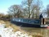
Does this help ? Photo (from 2003 trip). Rest of the album for that day here (Farmer's Bridge to Autherley, with a stop at Dudley).
-
My heat exchanger has no guts
Scholar Gypsy replied to Scholar Gypsy's topic in Boat Building & Maintenance
Thank you for this. I do indeed have a keel cooled engine. The bypass circuit (before the thermostat) is currently used to heat the calorifier. (see the two hoses going down in this picture - the large pipes at the top connect to the skin tank) I don't want to use that for heating for two reasons: i) the risk of engine overcooling ie the thermostat taking even longer to open ii) the risk of leaks, damage etc in the radiator circuit which would turn a mild inconvenience (water all over the floor) into a safety critical incident (engine stopping). I am (very belatedly) reproducing the system we had in the previous engine room (which had a BMC 1.5) and worked well. -
My heat exchanger has no guts
Scholar Gypsy replied to Scholar Gypsy's topic in Boat Building & Maintenance
Understood! My new radiator circuit will not be pressurised, the header tank is just that. So if I ever did get to use a backboiler then the pump would either pump water through the heat exchanger I am installing (drying towels in the summer), or through the back boiler (heating the boat in the winter), with various valves added to switch between the two modes. -
My heat exchanger has no guts
Scholar Gypsy replied to Scholar Gypsy's topic in Boat Building & Maintenance
Many thanks all. To answer the questions posed: the rads are not connected to a back boiler (yet) I have a small 12v pump (a cheaper version of the Bolin pump that I had in the previous engine room). It will normally only operate when the (electric) fuel pump is running. I would circulate through two new end caps - the photo shows one each of the blank and open ends. I need to work out whether the cool return pipe from the rads goes to the hot (front, input) end of the heat exchanger, or the slightly less hot (stern, output) end. It probably doesn't matter much in this case - I need to revise my thermodynamics.... I assume that the original stack (with no guts) was used simply to save money on a few metres of copper pipes. Putting in a replacement might reduce the flow in the primary circuit a bit, but I am assuming that it will still work fine -- after all pretty much all the flow has to go through the four holes around the cirumference near each end. This is precisely the set up we had with the previous (BMC) engine room. -
The "evidence" is a bit unclear. The C&RT leaflet says in one place: "All boaters should contact the appropriate lock office to book their use of the lock at least 24 hours in advance. ... and then later on in the Limehouse section "24 hours pre-booking required for out-of-hours locking in both summer and winter. All bookings must be confirmed with the lock keeper. " However I would agree with the views of several people that it is courteous and sensible to book in advance. I would not enjoy, for example, finding out as I was passing under Tower Bridge that there was a problem with the hydraulics at Limehouse ....
-
My heat exchanger has no guts
Scholar Gypsy replied to Scholar Gypsy's topic in Boat Building & Maintenance
Thanks - I hadn't got round to looking at their website. Interestingly it looks as though they still supply two versions of many models, one for raw water cooling, and one for keel cooling (without the tube stack). So now I just need to check with them that they are the same size as 20 years ago, and that there is no reason to add the stack. Their site says: "Some old assemblies are not listed due to the fact that castings are no longer available. However provided that the castings are in good condition tube stacks are available for units up to 40 years old, please check with our sales department for more information"ld assemblies are not listed due to the fact that castings are no longer available. However provided that the castings are in good condition tube stacks are available for units up to 40 years old, please check with our sales department for more information.Some old assemblies are not listed due to the fact that castings are no longer available. However provided that the castings are in good condition tube stacks are available for units up to 40 years old, please check with our sales department for more information.Some old assemblies are not listed due to the fact that castings are no longer available. However provided that the castings are in good condition tube stacks are available for units up to 40 years old, please check with our sales department for more information. -
So this weekend's task, at last, was to fit some radiators. All went well to start with: fitting them inside the boat, installing vent and drain taps as appropriate drilling holes through bulkheads (though my elderly Black and Decker was smoking rather a lot while drilling a 16mm hole through steel) connecting up the pump installing the header tank ... and then I took the heat exchanger on the top of the engine to bits. This is I think a pretty standard bowman with blanked off end caps. I was expecting to find a tube with lots of smaller pipes inside, around which the main cooling circuit flows on its way to the skin tank, with the radiator circuit going through the small tubes, via the end caps. Instead I found an empty tube with no guts inside. I would be grateful for any advice on where to source a tube with the pipes inside. Some photos below, the dimensions of the tube are 2 inches diameter x 18 & a bit inches length; and the length of the casting into which it fits is 16.5 inches. The blank caps are Bowman 3419, and the ones I plan to use Bowman 2679 - (but not the very old one from the similar system in the previous engine room. That was a BMC, this is a Mitsubishi K4E, installed 1994.) Many thanks .
-
Thanks - nice video. I was amused that they needed all three radar sets to complete this maneuver. .. I am not clear which way the tide was running at the time - and suspect they have tried to moor while facing downstream ??
-
SPCC are organising that cruise on Sat 31 May this year - with the added extra of a trip up the Deptford Creek... Details here.
-
I'm not correcting you - indeed I would agree. Could the OP let us know where they are coming from? If you are coming downstream from Brentford or Teddington then you really do need to leave the river at LImehouse, unless you fancy going further downstream through the barrier, waiting for low water, and then coming back upstream several hours later, and up Bow Creek. The Creek itself empties at low water. If you are coming upstream (say from the Royal Docks - see recent SPCC trip here) then it's an easy run up the Creek at or close to high water. A radio is even more advisable than usual, as there is tug & barge traffic in Bow Creek at the moment.
-
I believe that this posting shows what can happen if you moor facing downstream ...
-
The Imray's guide says Thrapston. Not sure why there ...
-
At Cromwell all three sets of gates point the same way - the tidal side can't be higher than the freshwater side, as the weir is open - and as you say are used to conserve water or increase speed of transit when only smaller boats are involved. Also, at most of the locks that have eight gates (ie one set for use when the tideway is lower and one for when it is higher), at very high tides the tidal water level will be higher than the top of the inner gates, which means the lock cannot be used until high tide has passed and the water has come down a bit. I nearly got caught by this at Bow Lock(s) a year or two ago...
-
Shower pump on/off swirtch
Scholar Gypsy replied to Jeanie920's topic in Boat Building & Maintenance
No, it won't matter. I assume the ring connector, when crimped, grips on bare wire, not the insulation. I assume you still have the two small grub screws that hold the ring connectors onto the terminal? We have the same switch on our boat, on our water pump. It has lasted about 20 years, I think. I don't think that model is designed to operate in a wet/splashy environment. So my hunch is that it is time for a new switch. It may also be worth cleaning the pump, removing hair, & putting vaseline on the impeller at the same time. -
I think this topic should be about bi-directional locks, not those that have long and short modes (eg Sunbury, Cookham, King George V dock etc). So for the former there are a number on tidal or river links that are truly bi-directional (Limehouse, Bow, Three Mills, Denver, Salters Lode, Dog-in-a-Doublet, Keadby, Dukes Cut in the past etc etc). These often use radial or guillotine gates and some that have three sets of gates, with the outward facing one just there to keep out a higher water level (eg City Mill lock on the Bow Back rivers, King George V, Torksey I think).
-
Shower pump on/off swirtch
Scholar Gypsy replied to Jeanie920's topic in Boat Building & Maintenance
It might be helpful to see a photo of the connectors (are the spades or chocolate boxes?), but it sounds like you need a new switch. Also, does the pump work properly (your comment "it makes a noise ... " made me wonder). If not then it may also be useful to measure the voltage delivered i) to the switch when it is turned off and iii) to the shower when the switch is on. In each case you would need to find a negative return wire. If there are other dodgy connections in the circuit that should help you find them. -
This bridge is where the passport was not handed over ... The ramp down to the towpath starts at the "B" in "Baynes". Slightly ridiculous plot, I thought ...
-
Interestingly, this does not seem to be very recent news. It is referred to in the most recent report and accounts (for the year to 31 December 2012) available here and I think discussed at the AGM in May 2013 (see here) and at a subsequent EGM. The AGM minutes include more detail of the business case for a reopened plane. If I have read the accounts correctly, £8000 of their reserves are in a restricted fund (called "engineering study") and the rest (£44k) are not, and so can normally be deployed as the trustees decide (subject to remaining within their charitable objectives of course). I should stress that I am not a member of the trust, or connected to it in any way, and there will be others who know far more of the detail than I do.
-
Thanks - I had the right canal but wrong location... I think the industrial estate is off to the left of the OP's photo. I have neither cruised that bit of canal (yet) nor been on that railway (Bath to Westbury - not sure I would describe that as a Great Railway Journey but perhaps we should have that debate on another website!).