Eeyore
-
Posts
1,153 -
Joined
-
Last visited
Content Type
Profiles
Forums
Events
Gallery
Blogs
Store
Everything posted by Eeyore
-
Model 2002 was produced from 1999 to 2003 inc and was based on the Yanmar 4TNE88-BME engine of 2190cc. There was also a model 2200 produced from 1998 to 2000 inc based on the same engine and available as either 45 or 50 hp. My Barrus training notes include most of the sales leaflets for those years, except of course the model 2002! It would be a reasonable guess that the 2002 was initially available as a 40 hp during the period that both were in production. Later production models saw the water-cooled exhaust restricted to the 50 hp models.
-
This post cannot be displayed because it is in a forum which requires at least 10 posts to view.
-
@cutandpolished61 are you still at Great Haywood marina?
-
Something from this range should be ok, https://www.merlinmotorsport.co.uk/s/samco-silicone-hoses-kits. plenty of other suppliers out there.
-

Second day living onboard my narrowboat... A little lost!
Eeyore replied to nashworth's topic in New to Boating?
Less flexible than a standard inverter setup, but well suited to high power appliances. By your own statement you don't need one. -
Did the data from John Deere mention the source of the “cavitation”? A similar sounding issue with (the much larger) Paxman engines was caused by running them at low loads. As a result the pistons didn’t get hot enough to fully expand into the liners, which allowed piston slap, which in turn caused ultrasonic vibrations in the coolant which eat though the liners! I wonder if the two are related? In any case you need to ensure the thermostat is functioning correctly and the engine is running at its design temperature. By the way the thermostat and cover on the ones I’ve encountered is rectangular and on the side of the head, a real pain to change. Check the cover on a flat surface and tighten the fastenings carefully as they are easily distorted. Have a look at the plumbing on the Barrus water cooled manifolds; they use the heat from the manifold to improve the warm up time. Might be worth a look if the JD isn’t already plumbed that way.
-
Second day living onboard my narrowboat... A little lost!
Eeyore replied to nashworth's topic in New to Boating?
Is @BlueStringPudding still in the same area; lots of experience with this sort of thing, and everything else about living aboard. -
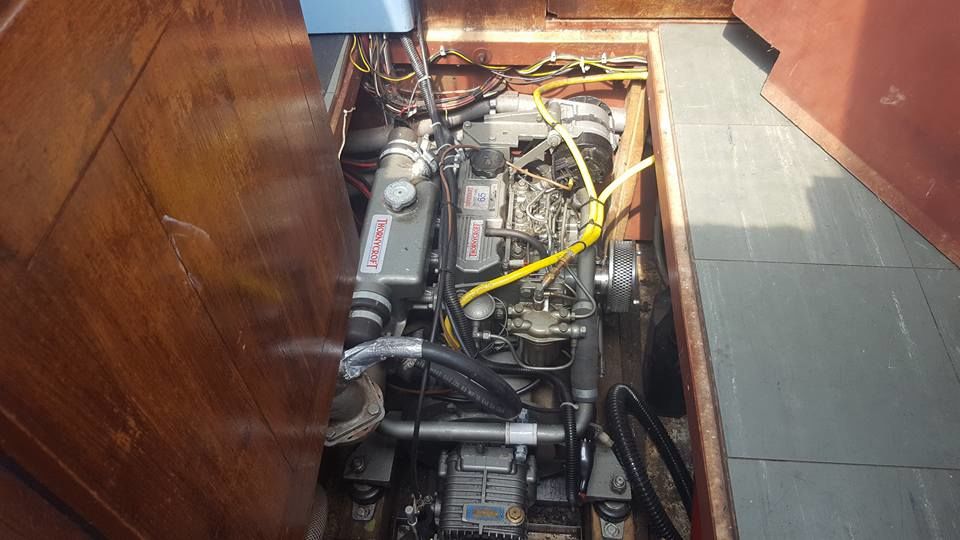
This image from the web shows the mounting for the upper alternator, the lower alternator (underneath on the opposite side) uses a fabricated mounting arrangement, which if memory serves uses the pto cover bolts. A simple reversion to single alternator using the standard mount for this engine can be made using this single point mounting version of the common A127 alternator. https://www.ebay.co.uk/itm/NEW-CANAL-BOAT-ALTERNATOR-HIGH-OUTPUT-75-AMP-A127-2-POINT-FIX-DUAL-TERMINATION/172013928453?epid=1649229235&hash=item280cd44005:g:alQAAOSw5VFWL5D~ Assuming of course that there is enough room in front of the exhaust manifold used by Thorneycroft.

-
As at Nov 07 the Mitsubishi part numbers were 31A46-00071 for build code 61DM, superseded by 31A46-00073 for all build codes (61DM, 65DM & T61DM). These are for vetus engines, but I'm fairly sure that yours will be the same build code. They are mutually interchangeable parts. Sitting the alternator on top of the thermostat cover, and transferring all the load into the housing was not one of Thorneycrofts finest moments.
-
Any replacement thermostat needs to sit in the centre of the casting with the sensing element facing the flow from the engine; probably from the base of the “T” , where the sensing element appears to be in the first image. Draw a line between “x” and “z” in your first image to give an indication of its position. In this configuration port “x” would be the bypass, and port “z” would be the flow to the cooler; the body may need rotating 180 deg should the flow differ from the original internal setup. A restrictor will be needed in the bypass to ensure the flow to the cooler (when the stat is open) is the flow of least resistance. So a little machining to provide a seat for the stat, and modification to the cover to hold the stat in place; possibly a perforated tube under the cover to hold the stat?
-
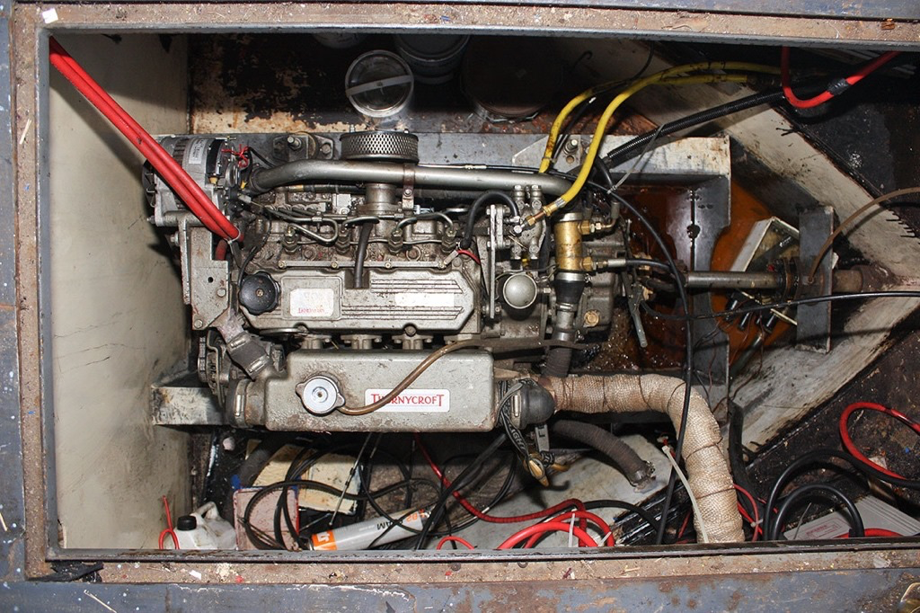
Looks like a T50 based on the shape of the exhaust/heat exchanger assembly. https://www.thornycroftengines.com/out-of-production-engines
-
The gearbox should be fairly straightforward. The current trolling option from Beta looks like this: Its going to be different to yours, but serves to identify the connections. The only two hoses you will need are the flow and return to and from the oil cooler, the layout of the oil cooler hoses is in the PRM 500 user manual. Anything else needs to be properly blanked off using original parts (plugs) from PRM. The spill return fitting in the above illustration is an additional hole in the top cover, yours may be elsewhere, but still needs blanking off. Electrically you will need to identify the wiring to the safety switch; which I believe is functionally the same as a neutral interlock which prevents the engine being started in gear. You will need access to the wiring diagram to confirm this. You can add the optional neutral interlock switch, or short the connections together if not; but only after checking the wiring diagram. The engine end is mechanically as simple as providing an anchor point for the outer of the throttle cable. Electrically I'm going to "bottle it" and say that a standard Beta wiring harness is the easy way to go; although removing a few solenoids and making good on the wiring doesn't sound too bad - does it?
-
Most engines with “energise to stop” solenoids will start, but not stop. A reasonably reliable way to identify “energise to stop” is the presence of a stop button. Forgot to say that some panels (possibly early Barrus) have a permenant live to the stop button, so the position of the key switch may be irrelevant.
-
Hi Ginny, I’m guessing you’ve been preoccupied with getting it to run again after turning off the fuel? There are a few other things that prevent (earlier) Barrus engines from stopping on the button; and best checked for whilst the engine is stopped. The least obvious can be the relay that lives on the wiring, part way between the engine and the panel. Hold it in your hand whilst pressing the button, you should be able to feel the “click” as it operates. It’s a common 1 inch cube type relay, take it with you if buying a new one as there are two ways in which the pins are numbered and connected internally.
-
electric installation - is this right?
Eeyore replied to Wittenham's topic in Boat Building & Maintenance
The shore supply connector fitted to the boat is generically refered to as an “appliance inlet”; the boat end of the shore supply cable will be fitted with a “trailing socket”. The shore side is a plug on the shore supply cable, and a socket on the supply bollard. We’re all used to taking the plug to the (fixed) socket, in this case we take the socket to the (fixed) plug; and then find new names for everything! -
MattyB, something like half a volt difference between the individual charge voltage of the two 12 volt batteries in your 24 volt setup is far too much for new batteries. There is clearly something out of specification with one or both, be that higher or lower internal resistance than the standard specification or something else; can someone with more specialist battery knowledge advise on how to approach the supplier with this issue? The use of a balancer is simply letting the battery supplier off the hook, and is generally viewed as somewhere between snake oil and a product looking for a market.
-
Wow, just been to something called Ikea. They have these things called “shelves”, really exciting groud breaking idea; I wonder if it could be adapted for onboard use? or too radical?
-
I think the first problem is to do with the arithmetic and charger settings. Two “12 volt” batteries in series to give “24 volt”, manufacturers recommended charge voltage for each “12 volt” battery is 14.4 volts; so you think you’ve set your charger at 24.8 volts for two of them in series. However if you measure (during charging) 14.4 on one battery and 15 on the other, then the charger must be set to charge at 29.4 volts! You then believe that you have set the charger to 28.2 volts and see 14.2 and 14.6, meaning that the charger is set to 28.8 volts! The second problem seems to be with one of the batteries, as I wouldn’t expect to see that much difference with two new and identically spec’ed batteries. I frequently see this type of inbalance on preserved rail vehicles which have a 12 volt bank either side of the vehicle which are series connected to provide 24 volt. It’s usualy just old age and a slightly weaker cell causing the issue; not something you should be seeing with your setup. As far as I can tell you’ve simply taken the available manufacturers data and adjusted accordingly for a 24 volt setup, not sure what everyone else is reading?
-
I did suggest that possibility in post 39 ?
-
So if the panel is 12 volt then maybe the second relay is energised by a 12 volt feed from the key switch and the contacts connect the 24 volt battery to one side of the alternator indicator light? This is basically the same as the wiring for the second indicator light on a dual alternator setup.
-
Have you ever found yourself traveling behind a car with a broken negative/earth on a rear lamp connector? All sorts of odd things happen when they brake or operate the indicators. Similar thing happening with your panel. ⚡️
-
Turn off all the switches and meter again between C5 and negative. I would expect it to be open circuit; your previous reading probably came via the lamps in the switches that were in the on position. This should show that the black wire going off panel needs a negative connection. Turn the switches back on and briefly touch a test wire between C5 and negative to see if the switches illuminate. If all is well find a permenant neg for the off panel wire.
-
Maybe one of the relays connects the 12 volt start battery positive to the midpoint of the 24 volt domestic bank, with the relay coil wired in “normal” split charge fashion from the ind terminal of the alternator. Yes I have seen this before, with 48, 24 and 12 volt batteries all charged from a single 48. volt charger! Far from ideal, but simple; the charging demands of the start battery being relitively minor. I would also expect to see a parallel link at the mid point of the 24 volt bank to further mitigate the effect of charging the starter in this way. At the end of the day a 24 volt starter would be the simplest solution, as converting the domestic to 12 volt would involve a rewire.
-
How remiss of us, welcome to the forum AndrewBridget ⚡️. A fairly quiet post for your first one then? Expect some banter along with good advice, enjoy.
-
You’ve got a lot of worms in that tin, haven’t you ?