Rincewind
-
Posts
145 -
Joined
-
Last visited
Content Type
Profiles
Forums
Events
Gallery
Blogs
Store
Everything posted by Rincewind
-
Propeller shaft flexible coupling 'broken? ?
Rincewind replied to moiuk's topic in Boat Building & Maintenance
38mm = 1.496063" 37.4mm = 1.472441" 1.5"= 38.1mm 0.1mm = 0.003937" A human hair measures approx 2 - 3 thousands of an inch thick, so not much in it! If you are certain that the shaft measures exactly 38mm then that is the size of taper lock you need. Measure the shaft in several places - not just on the end - to be sure it’s not worn. Just to be certain of a good fit, make sure all traces of oil, grease and any preservatives are removed from all surfaces prior to assembly. Don’t fall into the trap of believing that a smear of lubricant will aid assembly - it can have a detrimental effect. Oil trapped inbetween the contact surfaces can produce a hydraulic effect preventing a positive and tight assembly. And tighten up the two grub screws that are 180 degrees apart alternately and equally using a short length of tubing over the Allen key if necessary to get extra leverage. If you have room, tapping the coupling laterally with a mallet on one side whilst you simultaneously tighten the screws on the other side can often result in a tighter bond. Thats how it should be. Its not uncommon to have to drive a wooden wedge lightly into the taper lock to aid mounting on the shaft. (you just have to ensure that your not heavy handed whilst doing that to prevent it breaking!) But DO ENSURE you match the right size of taper lock to the size of shaft diam. -
Churning up the towpath into a mudpath, Little Bu****s Huh!
-
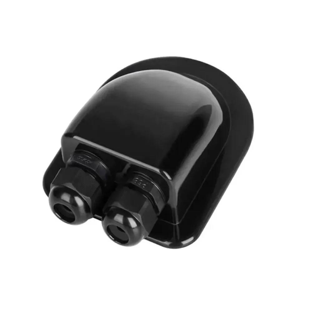
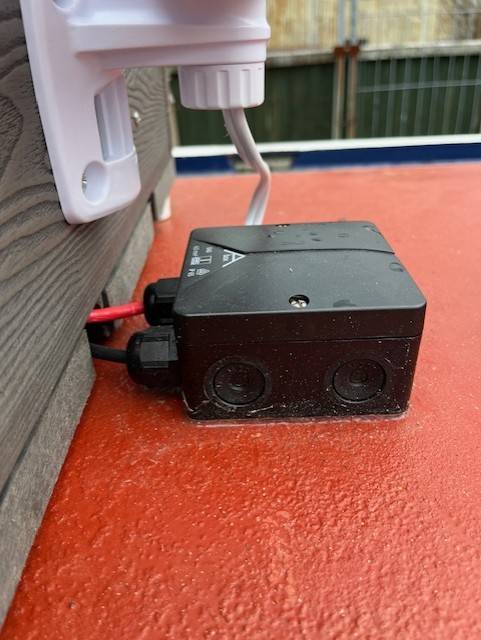
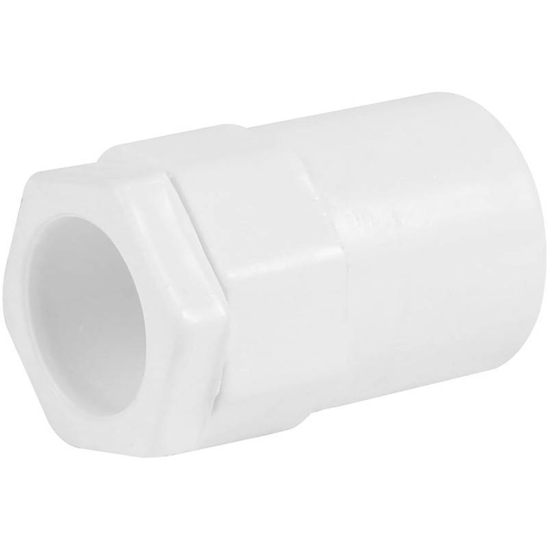
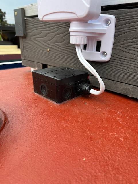
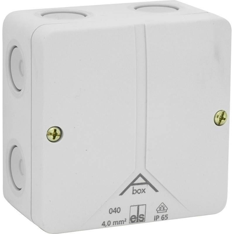
Regarding roof entry shrouds:- If you intend to pass the cables through a hole drilled into your roof then the weather protective covers usually supplied, (like the one in the picture below), are intended mostly for plastic / GRP caravan roofs where they are glued into position. They may not stand the test of time on a steel narrowboat roof. I would suggest a more rugged solution with an IP65 rated junction box like the one below. https://www.toolstation.com/ip65-moulded-pvc-box/p96199 To protect the cables from chaffing where they pass through the roof attach a conduit fitting to the underside of the box. This will allow the box to sit flush to the roof secured by two screws inside the box and you can seal the outside edge of the box where it meets the roof with suitable mastic / sealant. https://www.toolstation.com/pvc-conduit-female-adaptor/p91534

-
Puffer Parts - Iain Sutherland L & L Riddlesden
Rincewind replied to Fiona Highcock's topic in Waterways News & Press
Sorry to hear of his passing, Iain supplied me with many parts for my boat when I was fitting it out so got to know him well. I remember Iain having trouble getting paid for parts he had supplied to a boatyard in Wigan, with the boatyard owner always making excuses for not paying him by claiming cash flow problems. Iain & I hatched a plan whereby he would go into the office and ask for his money (knowing that the same old excuse would be proffered). I would time my entrance to the office a minute or two later handing over my mooring fees - in cash. The guys face was a picture! 😆 Iain got his money!!! -
Propeller shaft flexible coupling 'broken? ?
Rincewind replied to moiuk's topic in Boat Building & Maintenance
I know that you mentioned that particular engine mount was the most difficult to get to so I suggest:- If you are struggling to get enough leverage on the spanner underneath the engine bracket then tighten it as much as you can and then do the following:- 1, Use two spanners on the two top nuts in order to separate them. 2, Place a spanner on the nut underneath the engine bracket and lock it into position by jamming the spanner either against the hull or engine so that it cannot turn. You may have to ask someone to hold it in this position initially to stop it falling off while carrying out the next step. 3, Then use a 1/2" square drive deep socket to go over both top nuts, an extension - if required - and a long "breaker bar" in order to exert more torque onto the (lower) top nut. https://uk.farnell.com/sealey/ak730/breaker-bar-600mm-1-2/dp/4224514?gross_price=true&CMP=KNC-GUK-GEN-SHOPPING-PMAX-Medium_ROAS-Test1596&gad_source=1&gclid=EAIaIQobChMIhP3j0e3EhgMVsZRQBh0jQwuaEAQYAiABEgI6S_D_BwE 4, Then tighten the two top nuts together again by just moving the uppermost nut. If it slackens off again after doing this I would suggest that the whole engine mount should be changed for a new one. -
Propeller shaft flexible coupling 'broken? ?
Rincewind replied to moiuk's topic in Boat Building & Maintenance
Your welcome, Thanks for the feedback, much appreciated. -
Propeller shaft flexible coupling 'broken? ?
Rincewind replied to moiuk's topic in Boat Building & Maintenance
🤣 That a good example of Sods Law!!! You seem to have a further lock nut above the engine bracket, locking the two upper nuts together, which is good. It suggests that the the top nut(s) have not moved. (Carefully lever the engine up with a length of wood as you turn the bottom nut) I am not familiar with that particular engine mount so I cannot advise if the threaded stud has been designed to turn in its mount or not. (My instincts say it should not turn, but I may be wrong. Someone else on here should be able to advise). -
Propeller shaft flexible coupling 'broken? ?
Rincewind replied to moiuk's topic in Boat Building & Maintenance
Yes, you are on the right lines. If only one engine mount has backed off you may be lucky. Provided the top nut has not moved on that particular engine mount: Do not move the top nut and raise the engine by turning the bottom nut until the two nuts lock together - (with the engine bracket sandwitched in between of course!). Then check your alignment. that may be all that it takes. However if the top nut has moved over time, further corrective adjustment may be required -
Propeller shaft flexible coupling 'broken? ?
Rincewind replied to moiuk's topic in Boat Building & Maintenance
It appears from your photos that it is not aligned! To get the best from your "new" coupling I suggest you follow this procedure:- 1. Remove the stub shaft from the gearbox as Tracy suggests by removing the four bolts on the gearbox flange but before you do that, mark the two flanges on their edges so that they can be reassembled in the same position later on. Use a centre punch - or even a felt tip marker pen will do. 2. Completely remove both halves of the coupling from both shafts and put them to one side. 3. Measure the distance from the thrust bearing to the end of the shaft and record it. Grasp hold of the propeller shaft and try to move it in all directions, up, down, left, right, back and forth. If there is no discernible movement then you can assume all is well with the thrust and stern bearings. 4. Place an immovable object / pointer close to the end of the propeller shaft and rotate the shaft while observing the gap between shaft and pointer. If there is no noticeable difference in the gap then you can assume that the shaft is not bent and all is well with the prop shaft. 5. Replace the stub shaft onto the gearbox flange and bolt it up, - without the coupling. 6. Now you are ready to align the engine/gearbox assembly so that the shafts are both concentric to each other and parallel in all planes. This is done by adjusting the engine mountings, - assuming they are in good condition. This can be like juggling spaghetti at times but persist and it will all come together!😄 Do it in two stages, Roughly align the two shafts by eye so that they are as close as possible, just using your eyesight, and when you are happy with that, fine tune the alignment by placing a suitable straight edge along both shafts as a visual aid in the twelve, three, six and nine o'clock positions. If the two shafts are of different diameters place the straight edge on the larger shaft and use a feeler gauge to judge the gap on the smaller shaft. With this type of coupling a small amount of misalignment is acceptable but on the other hand - the closer the alignment, the better! At this final stage, with each adjustment of the individual engine mounts, lightly tighten the corresponding lock nut - do not rely on the weight of the engine! When you are satisfied with the alignment, firmly tighten all the engine mount bolts and recheck. 7. Now you can remove the stub shaft again and reassemble the coupling following the manufacturers assembly instructions (available online) Sorry about the long post but, Hey, Ho! Good Luck -
Propeller shaft flexible coupling 'broken? ?
Rincewind replied to moiuk's topic in Boat Building & Maintenance
In my experience a correctly fitted taperlock, i.e. one that is correctly tightened will not break up like that. Its usually caused by the taperlock bush becoming loose due to the assembly / securing screws backing off and then the stress induced by the motive force breaks the cast iron bush. I have even seen the rubber tyre sheer prior to mechanical damage occuring. If you have not come accross taperlock couplings before, I suggest you read the instructions for the correct mounting and dismantling procedures. They are good, tried and tested drive couplings if assembled correctly. -
Propeller shaft flexible coupling 'broken? ?
Rincewind replied to moiuk's topic in Boat Building & Maintenance
It would appear that the taperlock bush is broken into several pieces. It can only be repaired by fitting a new taperlock bush. There are some numbers / letters etched on the face of the taperlock bush that will help you identify the correct size, quote that number when purchasing a new one. If you cannot read the identification code, measure the shaft diameter carefully to determine if its either an imperial or metric shaft size - its important when ordering. The taperlock will conform to an engineering standard, its the bore of the bushes that come in different sizes - for the size of the taperlock in question. -
Talbot Wharf can usually accomadate you for short periods, most likely breasted up in the basin. Ask Tim & Lisa in the office. They also have the long term moorings south of the wharf, offside, but these may be full.
-
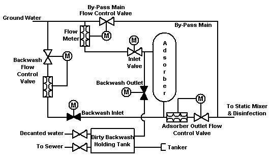
Does anyone really know what you are drinking? You may be interested to know that on the outskirts of Warrington there are several boreholes that are used to extract drinking water from aquifer's. At one of these boreholes arsenic leaches into the water through the bedrock. United Utilities were required to build an Adsorption plant to remove some of the arsenic before the water was fed into the mains. (Adsorption, simply put, = Very large filter!) Take note that I said some of the arsenic! At this particular site around 80% of the water was treated while the other 20% bypassed the adsorption process and was remixed before being fed into the mains! UU was not allowed to remove all of the contaminant - by law! (even though it was possible to do so). The percentage of removal / treatment depended of course on whatever the concentration of contaminant was in the water being pumped up and this was closely and continuously monitored. i.e., Adsorption percentage being treated was 'site specific'. This is not 'hearsay' by the way - I was tasked with writing the Company Standard / maintenance manual for this (and similar) Adsorption processes on behalf of UU. Apparently, a little bit of arsenic does you good! Personally, I prefer a large glass of malt whiskey!
-
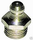
You could remove the fitting from the prop shaft stuffing box and fit one of these grease nipples, the nipple threads come in different sizes so take the stuffing box fitting with you when you buy one (or carefully measure the outside diameter of the thread), but you would need a suitable grease gun. I echo what agg221 suggests, its not a big deal if you are not going far.
-
The 'olive' can be fitted either way round, check that there is a 'shoulder' on one end of the nut that the 'olive' cannot pass through. The plastic / nylon pipe may have distorted or hardened (due to age or overtightening). If there is enough slack in the pipe, try cutting approx. 15mm off the end with a sharp knife and then reassemble. If you cannot push the 'olive' onto the 'new' section of pipe, the olive will be distorted and you will need a new one. It should be a close but sliding fit, ensure the pipe buts up fully inside the brass fitting. Do not overtighten. Just "nip" it enough that you cannot pull the tube out by hand. If that fails, follow Alans advice and buy a new section of pipe and new olives.
-
Paul beat me to it! You need a longer rope! from the boat, up and round a bollard then back down to the steerer taking in the slack as it rises!
-
Baton Twirlers Stage Protest (again)
Rincewind replied to Alan de Enfield's topic in General Boating
Unbelievable! I posted that tongue in cheek. Your mooring people don't miss a trick do they? When the calendar was altered by one of the Roman Emperors the plebs rioted because they thought they were losing part of their life, I think you should do the same! -
Baton Twirlers Stage Protest (again)
Rincewind replied to Alan de Enfield's topic in General Boating
Did you pay for the extra day in February? -
Many people use Floor Paint - with or without the sand / granules, and it comes in Red!
-
Baton Twirlers Stage Protest (again)
Rincewind replied to Alan de Enfield's topic in General Boating
Bring back Window Tax, that's what I say! And a Porthole Tax, And a Houdini Tax an all - Posh Buggers! -
Baton Twirlers Stage Protest (again)
Rincewind replied to Alan de Enfield's topic in General Boating
Ok, Guilty as charged mi Lud! But you get the jist.... BTW, I have had a BSC where the examiner has submitted the pass report but it was not updated on CRT's website, I had to update it myself when my auto renew application was subsequently rejected by the system. The point is, as MtB has confirmed, CRT are capable of checking credentials are in order - if they so wish. -
Baton Twirlers Stage Protest (again)
Rincewind replied to Alan de Enfield's topic in General Boating
It would not cost a penny more. Boaters that buy a normal license have to prove that they have insurance, a home mooring and a BS certificate otherwise they do not get issued with a license. Its the applicant that has to prove they have the documents in question, CRT do not do the legwork work for you! The bridge hoppers are just avoiding paying mooring fees and tax dodging, as we are all well aware. Just a few weeks ago there was a You-tube feature (was it on here?) where one woman was showing off her new build fatty (boat, not body ) and explaining (complaining) how she was forced to move every so often to comply with the CC license conditions. - Plenty of money to commission a new build and have it fitted out to her luxury spec but no intent whatsoever to financially support the canal infrastructure by paying for a mooring. -
Baton Twirlers Stage Protest (again)
Rincewind replied to Alan de Enfield's topic in General Boating
Agreed. If you want to live in a society and benefit from that society then surely it is only right for you to make a financial contribution to the upkeep of that society for the good of everyone including yourself. Even CC'rs, no matter where in the country they roam, directly benefit from the taxes most of us pay to local councils, Cost of policing, Fire & Rescue, road upkeep, rubbish removal, street lighting etc. etc. the list goes on.... When you apply for a CC license are you not declaring to the world that you no longer wish to pay your fair contribution of taxes? Perhaps its about time CRT only granted CC licenses when the applicant provides proof (receipt) that a local council tax, or substantial cash contribution, has been paid for that financial year to a Local Authority (of the applicants choice). There would be plenty of empty visitor moorings available then! -
Camshaft RPM sender - how does it work?
Rincewind replied to cheesegas's topic in Boat Building & Maintenance
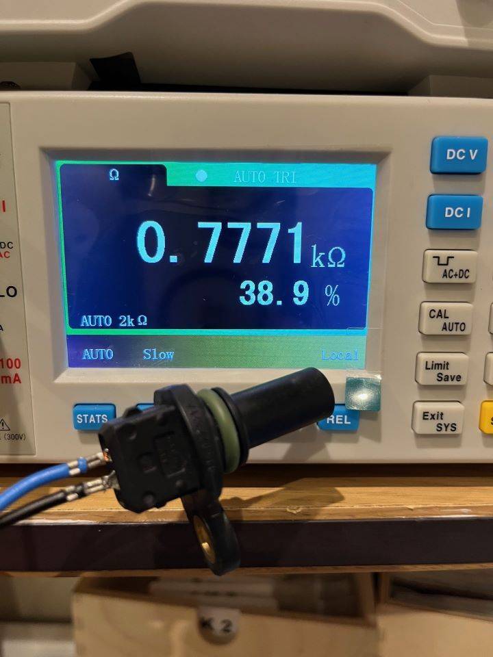
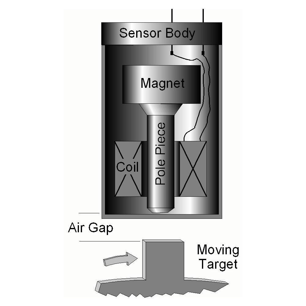
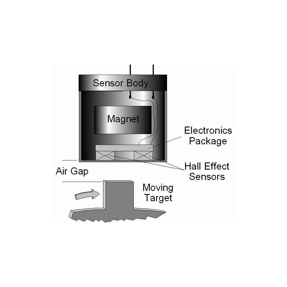
Depending on what you are attempting to do here I may have a solution. Question... are you wishing to repair / restore the revcounter back to its former glory? i.e. as per original spec? Or... do you simply want a revcounter that works electronically and is constantly accurate, i.e. not connected to the alternator in any shape or form as Quattrodave has suggested? If its the former then without physically examining the equipment you have, I may not be of much help, but if its the latter and you want a project to pursue, then I can point you in the right direction as some years ago I made, using a variable reluctance sensor (VRS), my own digital revcounter that is accurate to approx. 1 or 2 RPM at high engine speeds. (This accuracy was sufficient for my purposes, although you could make it even more accurate if you have the will to do so). As you already know, the variable reluctance sensor that you seem to have will output a sine wave signal (if it is working). Assuming that the signal is to be read by a microprocessor, that will most likely be housed inside the tacho instrument, the sine wave will have to be converted to a square wave prior to being fed into the microprocessor. When counting pulses, microprocessor's do not like sine wave signals and work best with crisp low to high square wave voltage signals. The point to note here is that, from the reluctor sensor to the tacho instrument, the cable you use should be of the shielded type with the braid grounded in order to prevent electromagnetic interference from other electrical equipment, e.g. alternators, corrupting the signal. - This can be important! (Less so important with Hall effect sensors as they are less susceptible to electromagnetic interference ). Hall effect speed sensors are also fitted with permanent magnets so "testing" the sensor by seeing if it is attracted to ferrous metals is not conclusive evidence of which type of sensor you are dealing with, however the number of electrical connections is a pretty good indicator. If it helps, I just measured the resistance of a spare reluctance sensor I have at home and it measures 777 ohms but do not read much into this as the resistance can vary widely from manufacturer to manufacturer. Also, be aware that the output voltage of a VRS can vary from as little as 8 volts to over a hundred volts depending on speed / make of sensor. e.g. The reluctor on my engine (over the flywheel teeth) at 642 RPM and producing1038 Hz, gave an output voltage of 152 volts - (both figures recorded on an oscilloscope). And that was at tick-over speed! Hall effect sensors normally output a voltage close to the supply voltage. i.e. If the input voltage = 5 volts then output voltage = 4.5 volts or thereabouts.
-
I love it! Its even got Solar Power! Brilliant, The owner / builder of that boat and I must share the same sense of fun. It gives a whole new meaning to the phrase "about to descend the lock"!!!