Steve56
-
Posts
332 -
Joined
-
Last visited
Content Type
Profiles
Forums
Events
Gallery
Blogs
Store
Everything posted by Steve56
-
If the rack will only move 1mm then it would appear that the pumps are gummed up with stale fuel. You will need to get the rack moving freely before you attempt to start the engine. You could try a little gentle force which will do no harm. There is nothing further forward that would stop the rack moving.
-
No there is nothing that will fly out. The only one thing is the fuel lift pump push rod. Once you have removed the pump this will just pull out. Then you should be fine. As I said before just make sure everything is clean and use a new joint.
-
It sounds as if you are talking of the crankcase door. Be careful when refitting. Make sure all remains of the old gasket are removed. Use a new gasket. Do not use jointing compound and torque to 8 lb ft. The reason for this is that all the oilways are in this door, so any internal or external leaks could give a reduced or no oil pressure.
-
 Thats the way I feel about them. I do remember a couple of years ago I installed a pump of the first one you mentioned for a customer. A week later the customer was complaining that something was making a noise and keeping her awake. It turned out to be the pump.
 -
That is a problem with this type of pump and it is a good idea to clean them out occasionally if at all possible. On the other hand how do people feel with the newer types of automatic pumps that do not have a float but rely on water sensing.
-
I know what you mean. On a 36 ft sea going boat I have 6 automatic bilge pumps and a bilge pump monitor. A lot of people say it is way over the top, but makes me feel happy.
-
I think on a canal boat there is no need of a non return valve. It is more often used on sea going vessels so as any water/waves will not run down the bilge pump outlet and fill the boat with water.
-
Severn Belle, just left Sharpness on a windy day.

-
I have come across very few cruisers where this can be done. The gearbox coupling is taper bored and keywayed, so the shaft can be turned and then run on an unworn part of the shaft.
-
Bear in mind that if you are swapping to this type of bearing you will need to ensure it cannot spin in the tube. On your old bearing there appears to be a notch in the inner end, which I would think locates in an internal pin inside the tube. Normally with cutlass bearings they need grub screws drilled and tapped into the side of the tube to ensure the bearing will not spin.
-
I don't really know of anywhere, but as Tony Brooks says T.J. Norris would be a good starting place. As for wear it is not really that easy to tell just by looking at it. It would need measuring to check. Really the simple way is to slide it on to a good section of shaft and see how it feels.
-
That's what I thought you would find buried away in the tube.
-
I would be very surprised to find a cutlass bearing in a Cheverton. It'll more than likely be a brass or something similar bearing.
-
The reason there are no details could be that it was not a Lister Petter engine it is a Petter engine. The only Petter engines included in the technical handbook would have been the engines in production at the time of the merger. I take it the handbook is the thickish one with the black cover.
-
Could also be an AB1.
-
Yes. It's a Petter A range air cooled.
-
A lot of the towpath on my local canal has been handed over to Sustrans and is part of the National Cycle Network
-
The 4 guys who originally started Beta Marine were ex Listers. There were no links at all. Beta would buy this engine from Lister as would any other customer.
-
Which sounds odd as Beta bought this engine from Listers and then did there own thing with it.
-
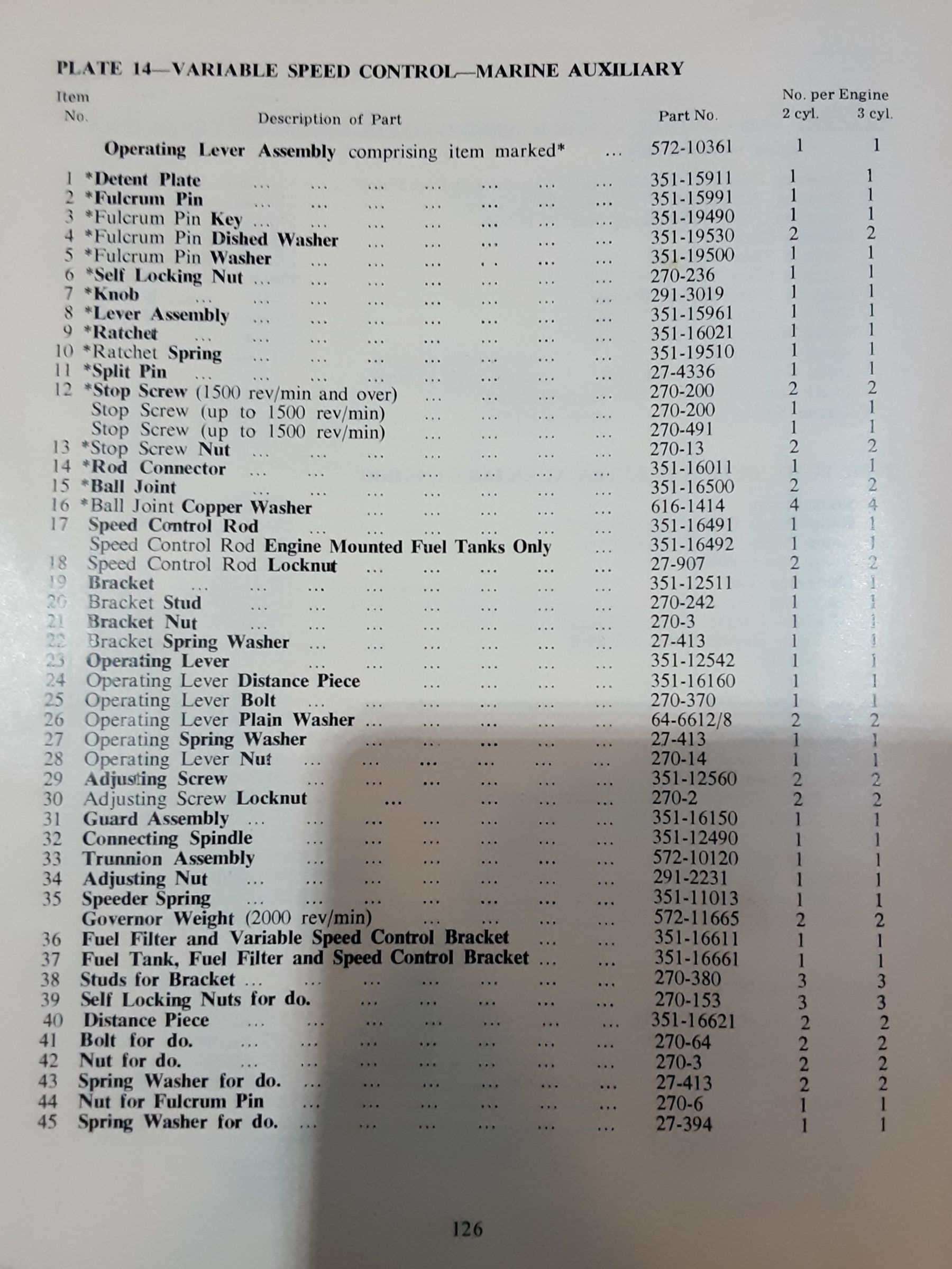
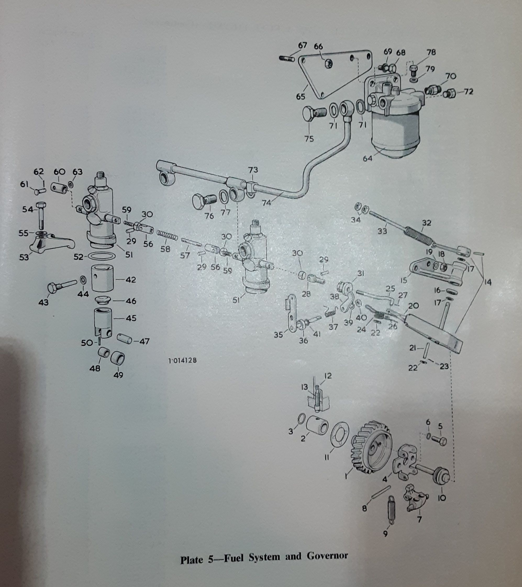
By pulling this rod in and out the speed will be altered. The maximum and minimum positions of the rod needs to be locked to give maximum speed and idle speed. It has nothing to do with stopping the engine. The separate stop lever is shown in the diagram in post 39, and is number 35.
-
A couple more bits of info. Rod no 32 comes from inside the engine and through a hole in the casing. The rest of the diagram shows the variable speed items.
-
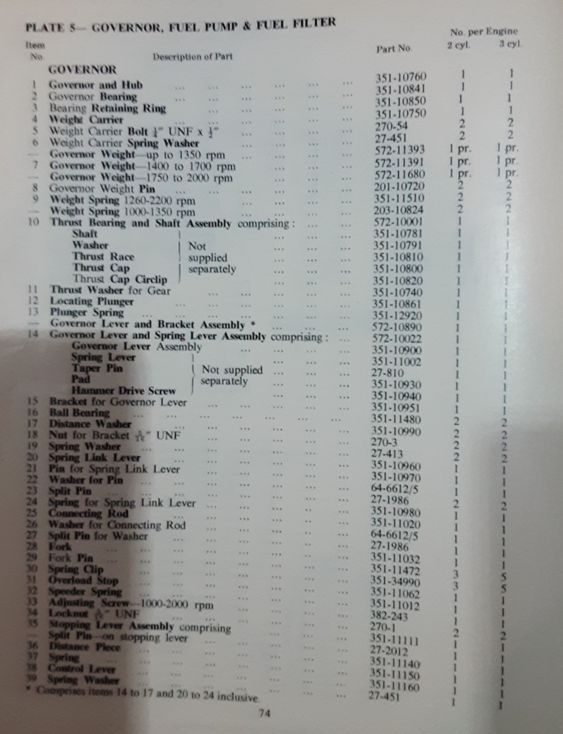
Fixed speed engines have the springs to give a much more stable speed and allow generators to maintain the speed within 4% between full and no load. The problem with this set up is getting the steady low idle speed. In fact more often than not the engine will not run at a low speed. That is the reason for fitting the correct weights without springs. This can be seen looking at the speed ranges in the governor weight chart.
-
A little more info on governors which may help.
-
This may help. A couple of tables showing governor weights. Note that fixed speed weights are linked by springs. Variable speed weights are not.
-
The Lister HA engine was fitted with a oil retaining ring, pt no 351-11520,and a felt washer, pt no 351-11530. Normally the ring will be fine, and you just replace the felt washer. From memory I think this washer may come in the joint set, but not 100% sure.