Mike Adams
-
Posts
819 -
Joined
-
Last visited
Content Type
Profiles
Forums
Events
Gallery
Blogs
Store
Everything posted by Mike Adams
-
I would recommend the process at Debdale. 4 years after blasting, zinc spraying, and two pack with an 85 year old hull and no signs of any problems. It is shame about the waiting list at Debdale. I was hoping to have my other boat done sometime. I have never used Zinga but other zinc based paints I have used don't seem to work that well. I think Zinga is single pack paint. If that is used as a first coat it may be the weak link between the steel surface and the two coat finish. I think there are lot of two pack coatings that will work well directly on properly shot blasted steel. The advantage of Debdale is that they have very controlled conditions inside the facility which gives much better control of the whole process. Time will tell if these processes are more cost effective but if I can get 10 years between repaints I will think it well worthwhile compared to spending weeks blacking in a dry-dock. The only disadvantage of two pack coating seems to be fading to a grey over time.
-
This boat is rather unusual for a 'narrow' boat being only about 6' 6" width of hull 62 feet long and quite slippery. It is a good copy of a Bridgewater Canal little packet from 1875 with a fine bow and long swim so as long as it isn't dragging the bottom it's good. It soon gets up to a good speed and takes a long time to slow down even on the shallow Basingstoke Canal so 55Hp is really not normally needed but at just over tick over at about 1000 rpm everything goes nicely. I am yet to try it on a river but it should go well enough. I have seen a widebeam brick (12ft beam x 2'8" draft) try to push its way along the Basingstoke - very hard on the canal and its banks due to the backflow around the boat. Isn't that why they gave up with wide beamed powered working boats on the GU? I am not anti-wide beam by the way but I lot of their modern hull designs (do they have any?) are not sympathetic to the waterways they are being sold to be used on unless they go at a snail’s pace or get a horse(or is that not allowed anymore because of upsetting continuous moorers). Apologies for rant.
-
The system is great apart from being a little too quick on tick over so I want to stick with it. The control valve and prv are integrated to the side of the reservoir tank all next to the engine at the front of the boat with just two pipes going to the stern to the hydraulic motor. As the motor is fixed displacement as well it is effectively a 2:1 reduction system (19cc/rev pump and 39 cc/rev motor). What I need is the hydraulic equivalent of a 'trolling valve' which fishing boats use. I think I need a flow control valve (electrically operated?) to take say 50% of the motor flow when engaged and the engine running at tick over. At 800rpm tick over the flow rate would be 19cc x 800 = 15200cc/min so if half that say is diverted through the valve, the flow rate to the motor will be halved and the prop speed reduced by half. This might make a two speed gearbox? I remember visiting Venice where the Vaporetto Ferries seem to have two speed gearboxes which give them higher torque when starting and stopping and then 'change up when under way'. I know that more modern hydraulic drives use a variable displacement pump which I guess gives infinite control of the flow and hence the prop speed regardless of engine speed but mine isn't in that league. I will see if I can find a suitable valve.
-
As it is hydraulic drive I maybe able to introduce a flow diverter at tick over to reduce the prop speed. Maybe a bypass valve to take 50% of the flow from the motor operated by an electrical switch? It's such a pain to have to drop in and out of gear all the time.
-
I will leave at 800 for now I set the speed with my optical tachometer -the panel tacho, that is about 50 feet away, seems to be quite inaccurate and reads way too low.
-
Does anyone know the correct or best speed to set the tick over on this engine? I can't find any reference to it in any of the paperwork I have. I can set it to run slow but it hunts when cold, runs smooth as it heats up but slows down and hunts again when it is fully hot to a point when its almost stalling. I think I must have it set too slow at about 600rpm. It was originally set at about 800rpm when I got the engine which seems a bit high and results in a bit too much progress at tickover speed. Setting it anywhere between 600 and 800 causes the engine to vibrate more than I would like.
-
It looks as if the power is daisy chained to the switches. A bad connection anywhere in the chain could cause the problems you have. You could disconnect all the wiring from the switches clean the contacts and tighten the spades.
-
I would first check to see that the equipment on the domestic side is actually 24v rather than 12v. Check a bulb for voltage designation on the domestic side and the engine panel this will show you the voltage in each system. If the domestic batteries were connected up to look as if they were 24v (ie all in series) they may have been shot and just rewired to boost the voltage(unlikely). A split charge relay will only work if both battery banks are the same voltage . The single alternator would have to be 24v to charge a 24v bank unless there is change over system which reconfiqures the 24v bank into 2x 12v for charging (unlikely). Maybe there was a second 24v alternator to charge the domestic set which has been removed. An engine is unlikely to be fitted with a different voltage alternator to the engine electrics. Hope this helps
-
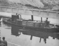
Noticed this riveted craft on ebay today. Pics are not clear but riveted consruction so might be an 'inserting historic'. https://www.ebay.co.uk/itm/canal-narrow-boat-project/202588068964?_trkparms=aid%3D111001%26algo%3DREC.SEED%26ao%3D1%26asc%3D20160908105057%26meid%3D085b6dc9e89249b5824b624039447a71%26pid%3D100675%26rk%3D1%26rkt%3D15%26mehot%3Dpp%26sd%3D202588068964%26itm%3D202588068964&_trksid=p2481888.c100675.m4236&_trkparms=pageci%3Ab5602d60-298c-11e9-b482-74dbd1801ed7|parentrq%3Abf8e2d8b1680ac7026ce3966ffcedf5b|iid%3A1
-
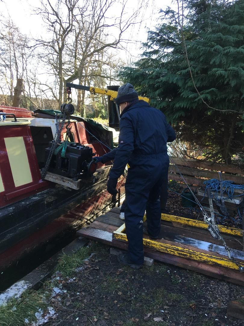
I have already fitted a second engine under the front deck ( 55Hp Isuzu). As the boat has a hydraulic drive it was easy to do this keeping the Kelvin in place. I did toy with idea of keeping both engines but that would be a bit silly. A Kelvin really needs to be in an engine room with easy access from the steering position and room to work around it. This wasn't the case with this boat( replica Bridgewater Llittle Packet) and getting to the engine meant clambering along forty foot of boat and down a very small hatch and into the less than full hieght engine room, with lots of opportunity for an accident in anything other than ideal conditions. I can now make a careful inspection of all the Kelvin parts in the warm of the shed and take it from there. Maybe an engine looking for a boat? Mike
-
At last it's out!

-
My reconfigured engine/skin tank and calorifier needs a replacement pressurised header tank to keep everything nice and clear of air. I have calculated that the water expands by 1/3rd litre between cold and hot so I am looking at about 2 litre capacity. I would prefer one that is transpanent with a traditional pressure cap. Anyone recommend one or should I just use an automotive one although these seem to have bespoke caps. There are plenty of alloy ones around but I would prefer one I can just glance at to check the level. Thanks.
-
Canal lateral a loire + a general book question
Mike Adams replied to magpie patrick's topic in History & Heritage
I believe the Loire was navigable for a long period by various shallow drafted craft. The Briare was built first and you can still see the operational lock that leads down to the river from the basin. As you pass along the Lateral Canal there are a number of branches, some which are operational that lead down to the river and are used by some traditional river/fishing boats. Ths Canal du Centre does not start until you reach the end of the Canal Lateral. Various French waterway guides cover the area in detail with a little bit of history ncluded. -
Yes all marked up and there was a pipe which seems to run down on to the crankshaft gear so the bearing must just be worn. Bearing in mind I don't think it has been overhauled since it went in in 1987 could be worse! I shall be using an engine crane which can be reversed using a counterwieght which has a capacity of 10cwt so that should be fine. 2 days work in end and thanks for the help. Putting it all back together will probably be a job for next winter but having the clutch loose and the timing wheels rattling probably made it sound worse than it is.
-
Thanks for the help. I am now down to the block and crank. The only problem I have found so far is the idler gear bearing being shot! Not sure yet how it is lubricated but no doubt I shall find out. The main job now is to lift the crankcase out. I recon if probably goes about 3cwt at a guess.
-
Is there a special spanner/tool to tighten this nut or do I need to make one up from scratch or does one just use a flat punch and a hammer. I noticed there are not any references to torque settings anywhere. I could make up a bit of steel tube with some notches on the end to fit the tabs with a large nut welded on the other end and fit it over the shaft and use a torque wrench. I didn't notice any shaped washer athough the nut itself is shaped and clearly fits one way around. Mike
-
I have now sorted the cylinders the last nut was the most difficult but eventually I used a 1/2" drive socket mated to 1/2 drain plug remover which had a 19mm hex to which I fitted a 19mm crowsfoot coupled to my 3/8" fine angled ratchet. I have now removed the clutch by sliding an old propsfaft coupling onto it and using it as a slide hammer, the nut of which was very loose, probably accounting for the slack I had In the forward and aft movement of the crankshaft. I have never seen such a strange arrangement using two sets of tapered wedges to hold the clutch onto the shaft. With these removed the cluch is very loose on the shaft so I may have to think if this can be re worked or something. I have also removed the flywheel and tomorrow I hope to remove the timing gears and case which should leave me with a lump consisting of the crankcase and crankshaft that I should be able to get out through the side door. Mike
-
It's lunchtime and a bit cold out on the canal. However one is off and 5 bolts on the back cylinder now removed just stuggling with the centre one at the front of the back cylinder. Thanks for the tip of going down the cylinder - I had't thought of that!
-
Thanks for the help. Pistons now out in a couple of minutes. I am now looking at removing the cylinders. I initially thought the studs went from the crankcase, through the cylinders and through the head. I see that ths is not the case and that I need to undo all the bolts in the crankcase which may take a while as it is quite difficult to get at. They seem much too tight to have been done up with an ordinary spanner. The clutch is unlined so I might have to improvise some sort of slide hammer to dismantle it. I am reluctant to take the shaft off the cone since the nuts are peened over but the cone is quite loose on the crankshaft. Mike
-
Thanks Richard I think the shaft unbolts from the cone but I am not sure if having done this you can detach the forward clutch from the crankshaft without removing the cone first. I am finding the instruction book rather thin on dismantling the engine. I am trying to strip it down to the crankcase and get the bits out through the sidedoor Mike
-
Hi I am dismantling my J2 in situ and have come across a number of problems. When I took the gearbox off it left the shaft and cone clutch stuck in the forward position. Any suggestions how to free it off (it's been stuck in forward for about 30 years as the gearbox wasn't used. Also the whole thing is a bit lose on the crankshaft. I am just about to remove the pistons. What position should the crankshaft be in when I do this and should I pull the bottom of the conrod through the starbord door or let it drop to the sump. Lastly is there any issue with removing the cylinders other than access to the retaining nuts inside the crankcase? Thanks
-
Feed positive into wiper of switch1, two wires from switch one (you need 2 way single pole switches) to the same on switch 2 then from wiper of switch 2 to load, single negative from feed to load
-
British Waterways "Uniform" Mid Century
Mike Adams replied to cheshire~rose's topic in History & Heritage
I've got some BW Wellington boots with the BW logo on the side! -
Pat I have fitted a Isuzu 4 cylinder engine in the forward compartment coupled to a new smaller voac pump. It doesn't sound as nice as the Kelvin but there is much less general noise and vibration and you can't hear anything from the steering position. Unfortunately I will now be able to hear cursing fishermen as we pass! When I remove the Kelvin we will have space for a permanent berth and now we can walk through the entire boat without needing to go on deck. Removing the roof of the engine room is a possibility but there are now welded hand rails across the roof access and my engine crane/gantry doesn't have enough hieght to get it out in one piece. If I dismantle the engine in situ I can slide the block though the boat and lift it through the side door.Well that's the plan. I will sent some pictures when the J2 is out. Mike
-
Hi Pat. No, but I have both stripped out all the internals and motored the boat on the shallow Basingstoke and I can say that it steers perfectly and I haven't noted any significant assymetry on the stern. It is quite a fast boat and I suspect the author was going to fast but we have lost a couple of cylinders since then! If you go out of the channel it does pull more to the side more than some others I have steered but I can't see any obvious reason for this - maybe it's to do with the steering position as you have a differnt viewpoint compared to a tiller and the rudder arrangement is slightly different with the fixed forward section.