Pluto
-
Posts
4,512 -
Joined
-
Last visited
-
Days Won
2
Content Type
Profiles
Forums
Events
Gallery
Blogs
Store
Everything posted by Pluto
-
Much certainly has been lost. The only English description of canal building is the article in Rees Cyclopedia, published in 1805, and that is comparatively brief. This lack of technical publications in English is probably because craftsmen-taught English canal builders did not need anything beyond that passed down to them, plus what their intelligence could develop. This lack of contemporary published technical works is why I translated Maillard's book, which was based on his visit to English narrow canals in 1795. As you have suggested, clay was too heavy to carry any distance, and its availability locally depended on the local geology. I have been going through the Engineer's Reports sent to the Canal Committee during the construction of the northern section of the Lancaster Canal. There Sammel is sometimes referred to as being cut through during construction, and noting that it could be used elsewhere nearby for lining the canal.The description in the Reports is very similar to thatb given by Maillard in his canal engineering book. I have found reference to similar material in the L&LC Engineer's Reports, particularly for the length above Johnsons Hillock, which had a reputation for leaking. Not all people needed to pay a toll. A land owner through which a canal passed could be given the right to a pleasure boat, but not to pass through locks, while owners of farmland could have manure delivered without payment. In the 1920s, the L&LC did investigate what comprised manure, and what was being carried under that title. Isn't canal history complicated.😀
-
The following was taken, I think, from the 1973 MSC/Bridgewater guide. Not sure what £190,000 is in modern terms. BRIDGEWATER CANAL Note on collapsed embankment crossing the River Rollin near Altrincham, August 2nd 1971, andthe major reconstruction of the canal to restore navigation. On 2nd August 1971 at about 07.20 hours the Altrincham Police received a report from two eleven year old boys thatthere was a leak from the Bridgewater Canal near the BoIlin Aqueduct. At 07.50 hours the first stop logs were inserted atAgden and by 11.30 hours stop log dams on each side of the breach had been installed and the remainder of the canalwas safe. The canal in Manchester had dropped 14 inches which was made good with water from the River Medlock by3rd August. The canal crosses the River Bollin at the site of the breach on the largest Bridgewater Canal embankment; thedifference in height between the canal and river level being thirty-four feet. The canal had washed a hole in the embankment 90 feet wide and some 20,000 cubic yards of material had been deposited in the river bed. The cause ofthe disaster will never definitely be established, but detailed discussions with the Engineering Staff of BritishWaterways Board and circumstantial evidence, leads us to believe that the cause was a complicated leachingprocess of fine sand particles from the bed of the canal which had continued over the two hundred year life of theembankment. There have been several other very similar failures of high canal embankment where the canals hadcrossed rivers. The failure no doubt resulted from slight seepage at canal bed level and special precautions have been taken to seal the canal bed of the new embankment and also to check the canal bed where the Bridgewater crosses the River Mersey. The design and reconstruction of the aqueduct and canal embankment was under the direction of Mr. Blyth the ChiefEngineer. A detailed survey and cross sections were immediately taken to establish the magnitude of the task. Indealing with an old structure it is always a problem to decide where to draw the line between repair and renewal anddifficult decisions had to be made. The Company are as yet however bearing the full cost of repairing the breach which together with the associatedcost of rebuilding Woodhouse Lane aqueduct is likely to amount to nearly £190,000. The Inland Waterways Association representing the pleasure boat owners, and other amenity interests, were veryactive in organising support for the restoration. They held a rally of seven hundred boats at Lymm in August 1972,which in spite of atrocious weather was very well attended. They hope to be able to contribute to the restorationwork. The contractors were Messrs. Harry Fairclough & Co. Ltd., of Warrington, for the main restoration and WoodhouseLane aqueduct, and Messrs. A. Monk & Co. Ltd., of Warrington rebuilt the wing wall of the Bollin aqueduct. The canal will be reopened in September, and the Company would like to place on record their appreciation of theefforts made by the contractors and the understanding shown by the canal users.

-
This is a load of b*****ks. There were several Bridgewater Canal Acts authorising its construction in the 1760s and 1770s whose terms are basically still in position, though perhaps slightly amended by the MSC Acts. On the method of construction, although one of the earliest canal embankments - there are earlier ones on the Bridgewater - it did remain sound for 250 years, something which I suspect few modern structures will achieve. Brindley, and other contemporary canal builders, learnt their skills from older craftsmen, with knowledge being handed down verbally. This would have included the assessment of different types of earth, and their stability.Those craftsmen who rose to the top of their trade, such as Brindley and the other canal builders, were not stupid, and probably had higher levels of intelligence than most at university today. We have lost much of that information which was passed down from one generation of craftsmen to the next. For example, where canals needed to be lined to make them watertight, they did not use clay as we know it today. Sources of this are limited and it was too heavy to carry any distance by road. Instead they used a mixture of suitable earth and small stone, known as 'Sammel'. The name probably comes from the German, meaning 'collection'. This type of earth could be found naturally in many places, and it seems to have turned up during construction. Any excess was then used elsewhere close at hand for lining the canal bed, and is why puddle was usually at least four feet thick. This is just one of the many facets of canal engineering that have been virtually forgotten because craft skills are no long passed down by word of mouth 'on the job'. Training in a college or pseudo university just doesn't cut it for producing really good skilled workers.
-
ISTR that after the 1971 breach, a 'flotilla' was arranged in each direction to allow boats to get back to their home moorings. However, the Ashton and Peak Forest have opened since then, so such an operation may not be seen as so important. Regulations may have been watered down for the trip as there were several safety boats accompanying. Others may be better informed.
-
Is Brian Houlton still alive? No one knew the canal and its engineering better than him.
-
Prior to the development of soil mechanics using calculus, embankment construction was pretty much sorted out by the early 1800s. Smeaton (details are in his published Reports) and Jessop had done much work during the construction of the Grand Canal across terrain which would probably be avoided today. Whitworth could not have built the L&LC through East Lancashire had he not had a thorough knowledge of a reliable method of construction for the eight major embankments on this section. The control of drainage was essential, with drainage channels excavated either side of the proposed embankment. It was then raised in stages, with a small embankment raised either side next to the drainage channels, and the space inbetween filled subsequently to form the main embankment. Allowance for settlement was also made, as can be seen in Maillard's drawings for an embankment. One of the main problems for early 19th century canal and railway engineers, and this also applied to reservoir construction, is that they used a profile of around two horizontal to one vertical on both embankments and cuttings. After the passage of time, and the introduction of soil mechanics, it was found 3 to 1 would have been better. These ratios would vary depending upon the type of soil found. Whilst Brindley's Bollin embankment failed after 250 years or more, that is somewhat better than the public buildings we erect today which only last 30 years.
-
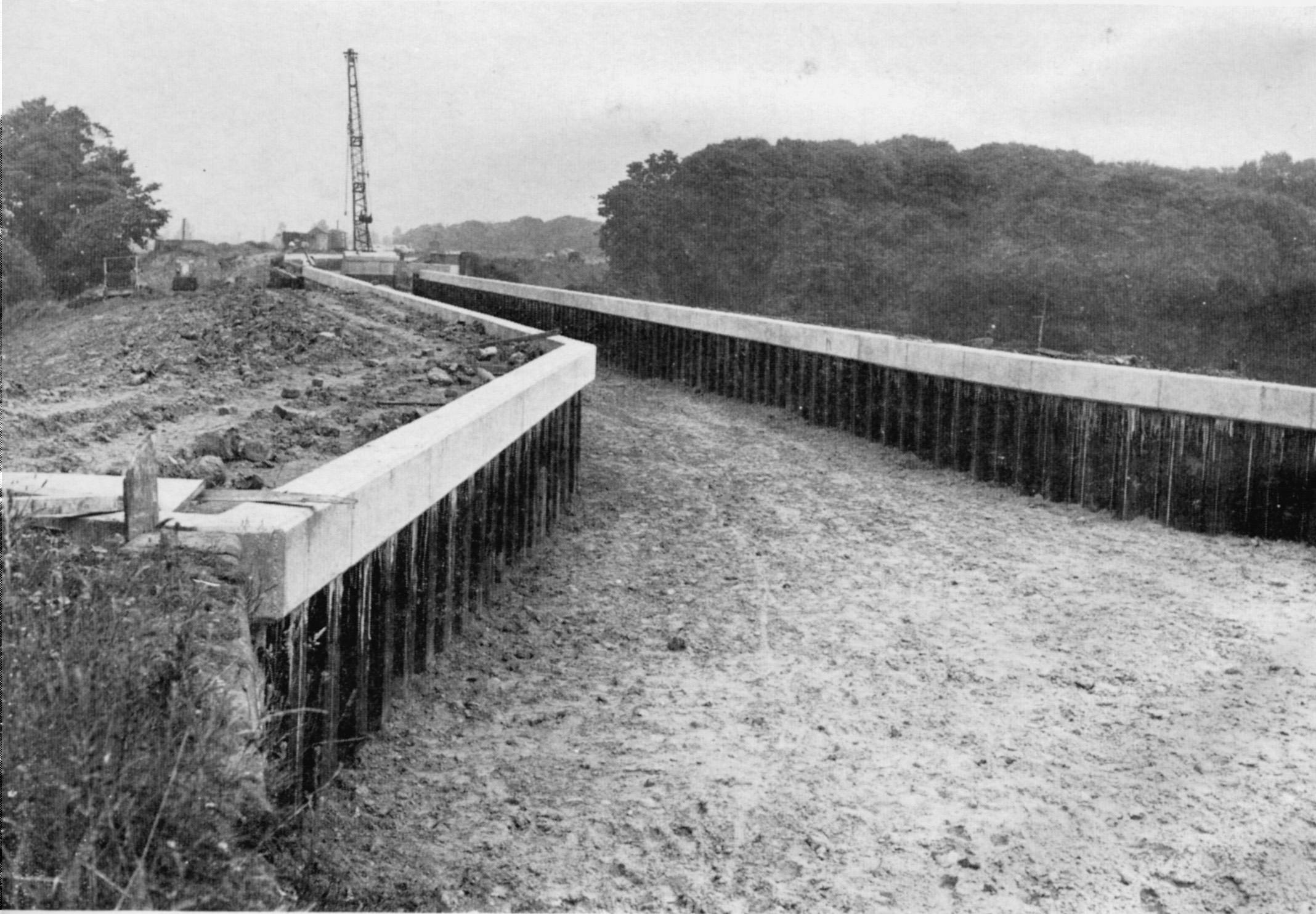
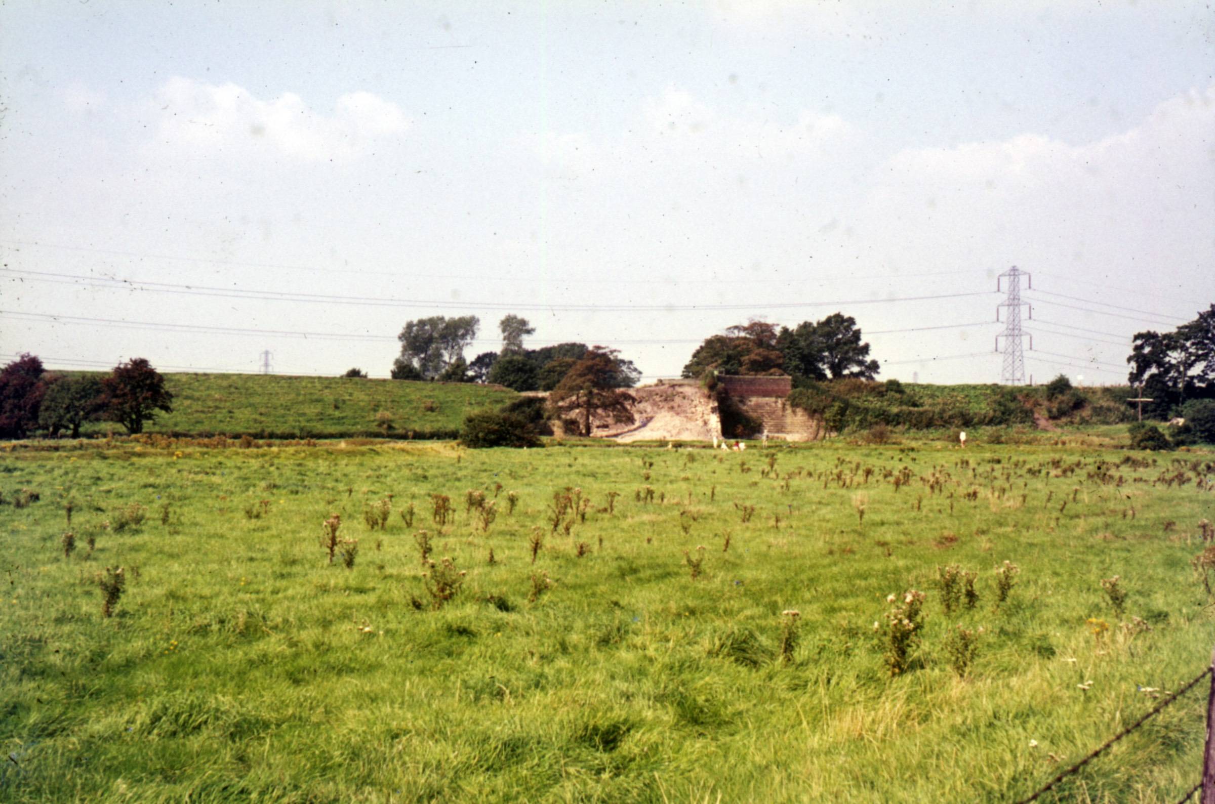
I seem to recall that one of the problems with the 1971 breach was that Barton Aqueduct was open for the ship canal, and that it took a long time for the levels either side to equalise so that Bridgewater Canal traffic could pass. The Rochdale and Ashton were not open, so water supplies to the canal in Manchester were limited. Similar problems resulted at the single gate at Dutton. On stop planks, for a breach like this several sets would normally be used at narrows along the canal before a good seal could be made. Once the flow of water was controlled/stopped, the set nearest the breach can be set properly and the length from there to the first successful stop could be filled. When the Bridgewater first opened, there was much interest in Brindley's automatic stop gates which lay on the canal bed until raised by the flow of water caused by a breach. Unfortunately, in use they became silted over and inoperable. The L&LC style of normal lock gates without balance beams fitted in bridgeholes either side of embankments were more successful. I seem to recall that there were problems with the flow of water in the Bollin right from the start, and the layout of the river was adapted to improve matters. Unfortunately I am about to move, so my library is inaccessible. Any culvert built under a canal during its construction will remain the responsibility of the canal company unless they have been asked to allow improvements by another party. The 1971 breach is seen below in a photo by Roger Lorenz.
-
I have been doing some research into the construction of the embankments on the Bridgewater recently, looking at the way spoil was deposited as described in contemporary publications. Visitors describe the use of two 3 to 4 feet wide boats, with a hopper between. The boats floated out onto some type of split wooden aqueduct, dumping the spoil between the two aqueduct spurs. All the descriptions are vague on detail, with that by Hogrewe in his 1780 book on English canals probably being the best. He certainly had engineering experience, unlike most of the others. I am currently finishing the layout, and have a few more details to add, but hope the translation will be out soon. Basically, I suspect Brindley had that many problems with constructing embankments on the Bridgewater, that he subsequently only built contour canals. The load-bearing embankment was probably the most important engineering development on English canals, and they saw the first steps in soil mechanics. Along with the excavation of deep cuttings, they opened up new possibilities not previously used to any great extent elsewhere in Europe, where most canal construction problems had already been overcome.
-
I am glad you liked Brightwork. I was fortunate to meet Sam at a canal event at Blackburn in 1993. He was a true craftsman who was happy to share his knowledge. He said that as an apprentice you were given one chance to paint a straight line, then passing on to do the scalloped edges to the framing. The yard owner did all the proper decorative paintwork, and Sam was allowed to develop his skills over the years, until one day the owner had a bad cold and told Sam to take over. As a result of our meeting back in 1993, we were able to revive interest and knowledge of a canal tradition. On Norfolk boats, you should contact the Norfolk Wherry Trust, https://www.facebook.com/NorfolkWherryTrust/?locale=en_GB, who should be able to advise. Their proper web pages don't seem to be working at the moment.
-
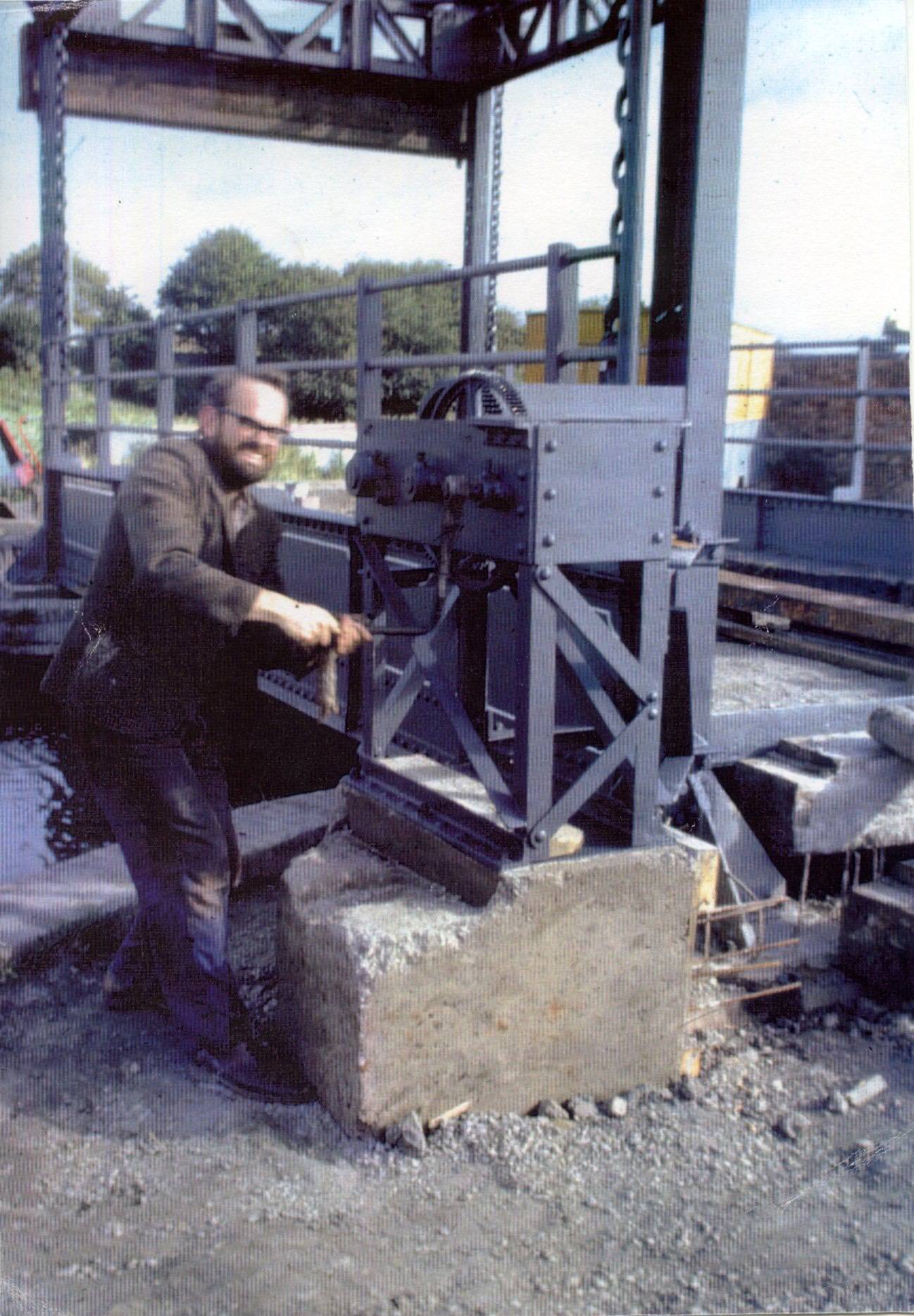
Regarding lift bridges, I was sorting through my collection, prior to moving, and came across this one of me raising the lift bridge at the Black Country Museum for the first time after re-erection.
-
I sang in the choir at the carol service at St Mary's, Gisburn. Not close to a canal, but the church has several memorials to members of Lord Ribblesdale's family from Gisburn Park. Around 1770, the then Lord Ribblesdale installed his young son, fresh from university, as MP for Clitheroe. Wanting to make a name for himself, he successfully opposed the Settle Canal. The Canal would have taken water from the Ribble, which would then pass down the L&LC to supply the proposed Leeds & Selby Canal. Thus Lancashire water would have fed a Yorkshire canal, so it was easy for him to raise objections, and the canal never received its Act.
-
That would seem to me to be the correct interpretation. Translation of technical words, particularly from old books and manuscripts, does tend to be difficult. Often there is a more specific word in one language, though its exact usage can be difficult to assign as we are unsure about exactly what is being described. Has the design of existing structures changed over time, and should we rely upon artist's impressions, where the artist normally has no engineering training? This list of words in German, mainly describing flash locks, shows the difficulty in such translation. They are as correct as far as my understanding of such structures goes. German lock terms Archen Another word for Schleuse or Lock, probably when associated with a weir.. Doppeltschleuse The same as a Fang-Schleusen. Durchlässe Flash lock with maximum of 3 ft fall. Fang-Schleusen Two flash locks close together such that they form a simple chamber lock. Fährlöcher Flash lock of the simplest type. Freiarche Weir with opening for passage of boats. Kammer-Schleusen Chamber lock. Kasten-Schleusen Box locks, where the wooden frame of the chamber has beams over the chamber. Used where the ground is soft. Kuppelschleusen Riser locks Schleusenwehr Weir with opening for passage of boats. Schüttbalken Rymer. Schütttüren Paddles. Schütztafel Single lifting gate Stau-Schleusen Flash lock, with up to 6 ft fall. (?) Stemmtüren Lock gates. Tummelfalle ? Zapf-Schleusen ?
-
In French, aqueduct was a term used for many features which carried water; and its Preston Brook.
-
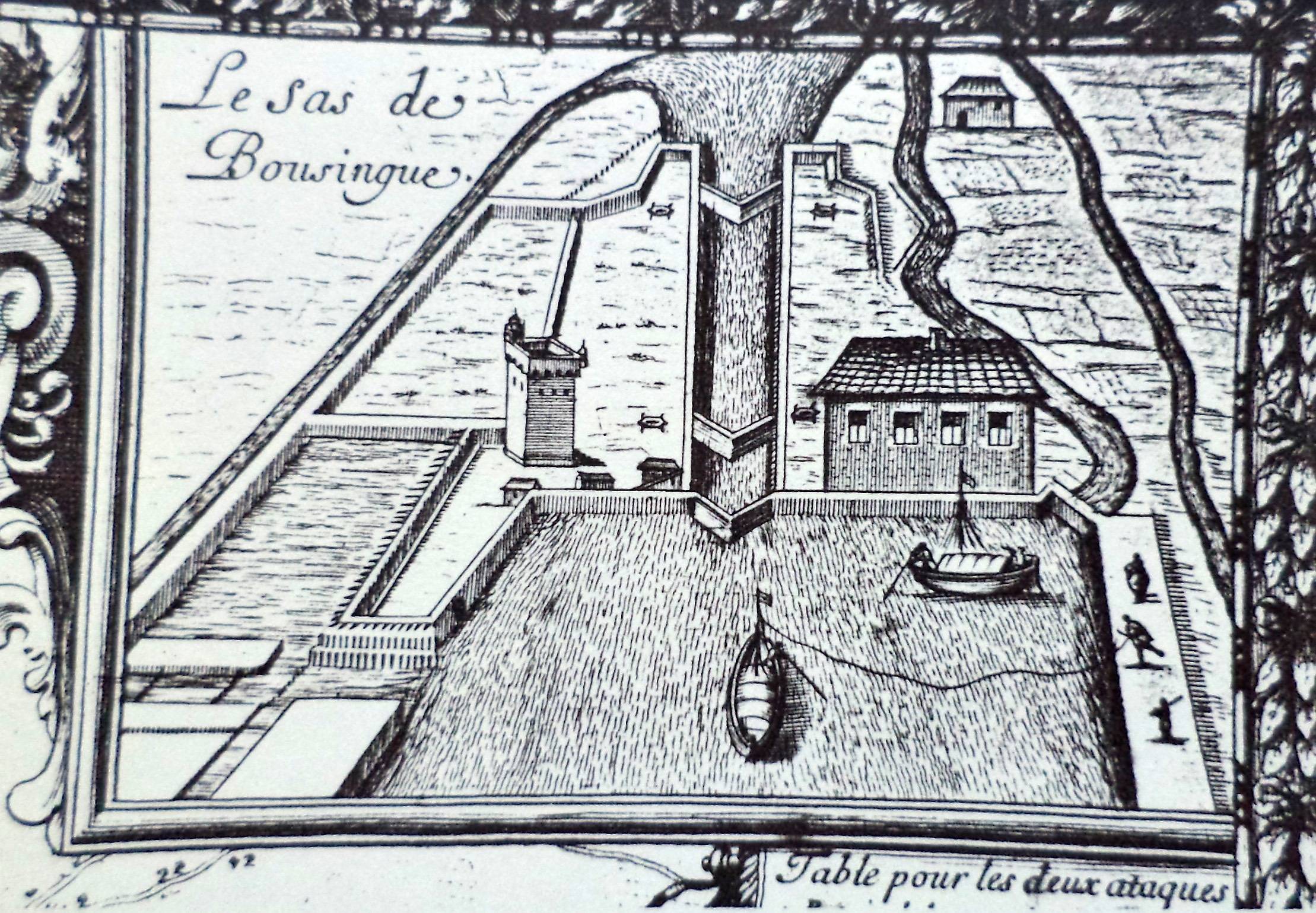
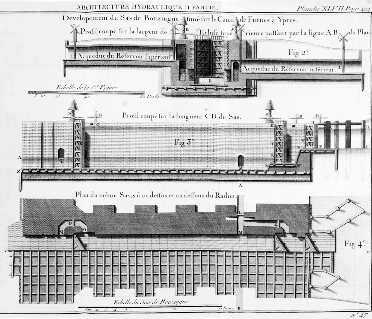
This is the lower lock at Boezinge. on the Ypres-Ijzer Canal. The original lock here was the first to have a side pond. The canal opened in 1637 using Overtoom, inlined planes, with a lock being built here in 1640 with a possible fall of 6.6 metres, though the exact details are vague. Very soon afterwards, a second set of upper gates were fitted, with water from the short section between the two sets of upper gates draining into a side pond. The rest of the water drained into the lower canal. The first, 1648, drawing shows a reservoir on the left, but by the time of Belidor's Architecture Hyraulique, 1753, an additional reservoir had been built on the right. Unfortunately the lock was totally destroyed in the First World War, and was subsequently replaced by two locks, the one shown being on the site of the original. It is likely that the Boezinge Lock was also the first to use ground paddles. The lock at Willebroek, on the Brussels Canal, has been suggested as the first to use side paddles, but contemporary drawings suggest otherwise, and much of the original documentation was destroyed during the siege of Brussels during the thirty Years War, so it is difficult to confirm anything.
-
What happens when a boat with a 1500 T load hits the gates - Moselle
Pluto replied to Onewheeler's topic in General Boating
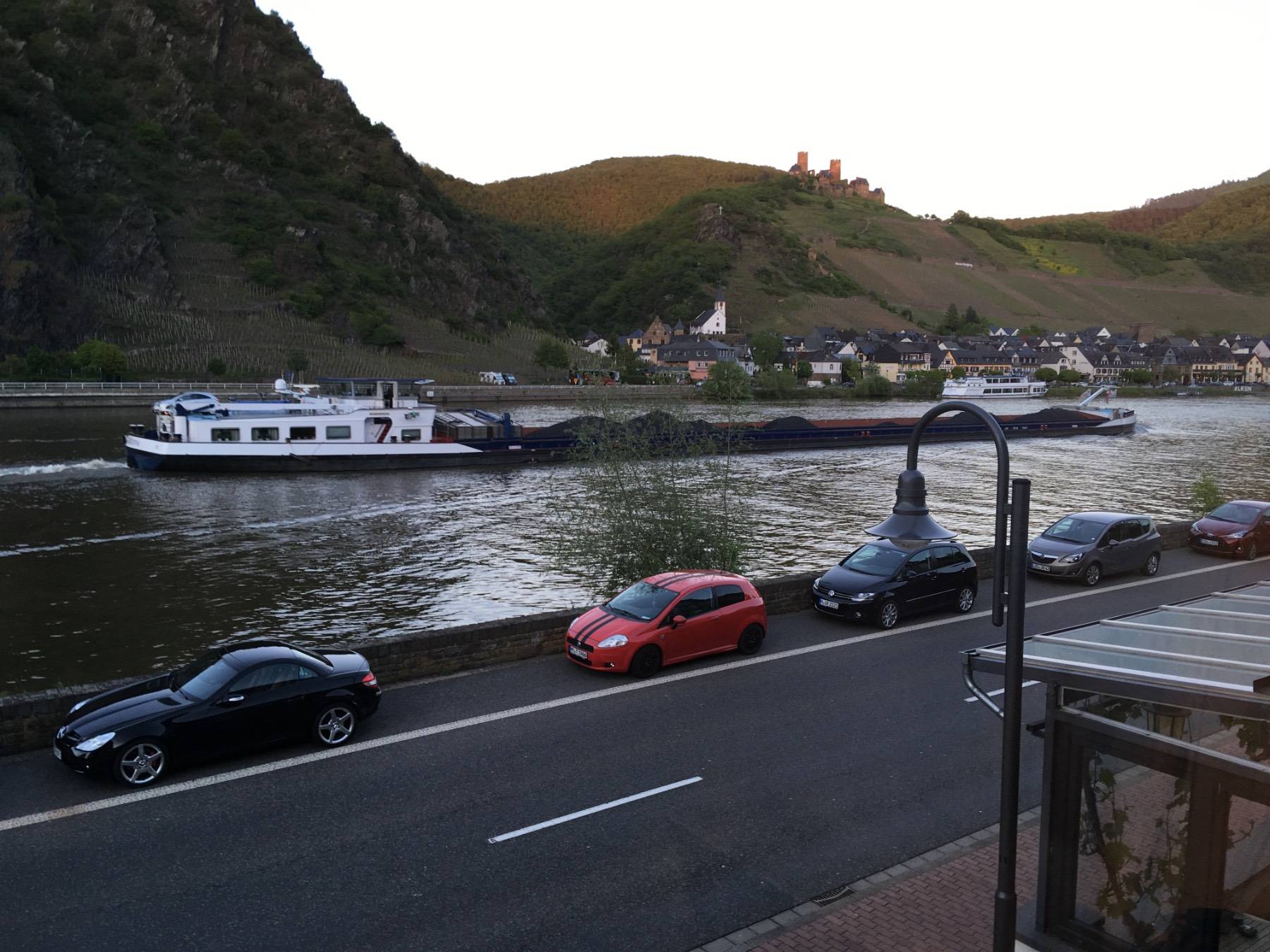
I can recommend the Mosel valley for a holiday, although there is not much commercial traffic compared to the Rhine. This is the view from our hotel room at Kattenes, just below Müden, in 2019. It was just an overnight stop, but we have stayed longer at vineyards, many provide accommodation in Germany, in both the Mosel and Rhine valleys where there was plenty of opportunity to try their 'harvest'.
-
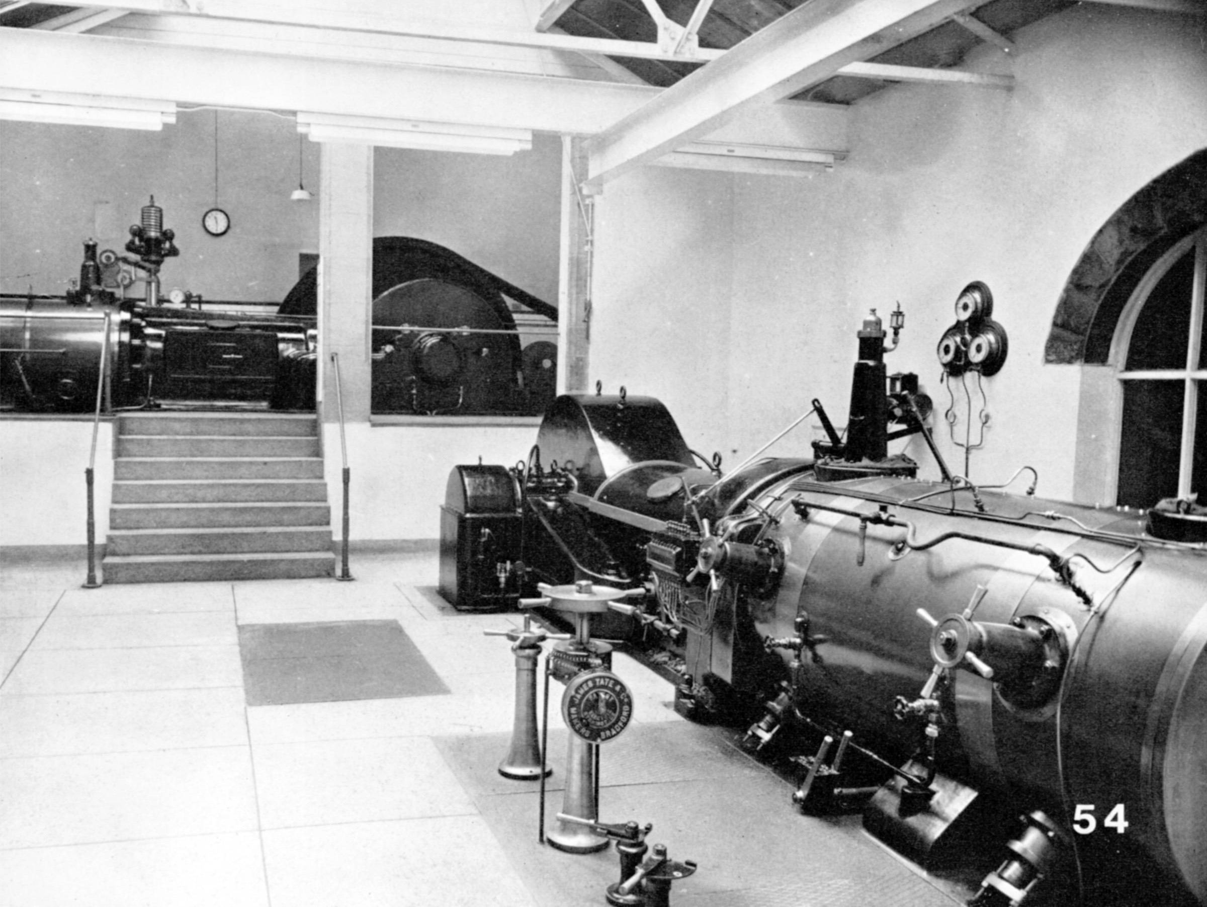
Back in 1974, I took out the Politt & Wigsall Uniflow engine at nearby Dobroyd Mill. It was the one at the back, and three of us got it out using a couple of block & tackle. Not sure if it would be allowed today. PS Photo by George Watkins.
-
Citizen science request – UK watercraft duty cycles survey
Pluto replied to Dr Nick's topic in General Boating
Can I ask what expertise you have relevant to fuel usage on boats, so that you can understand the veracity of responses? -
A whanning hole is where you turn your boat on the L&LC.
-
The first canal filming I was involved with was a Bavarian TV program on a canal holiday on the L&LC back in 1991. The director came over several months beforehand to sort out what they would film and from where, as well as arranging people to help and/or film. Making the film was then fairly easy as everything was organised. Since then, with the introduction of digital filming, even the professional film makers seem to have little idea as to what they will film, making up their mind on the hoof. I did some work with Mathew Corbett about 20 years ago - I was neither Sooty nor Sweep - at Bingley 5-rise. He was fuming at the teams lack of professionalism by the time we were making the tenth go at an interview. They were operating on the point and squirt method of filming, and that lost all spontaneity in the interviewee's response. If you do things on the cheap you tend to end up with rubbish. I tried not to get involved with filming after that.
-
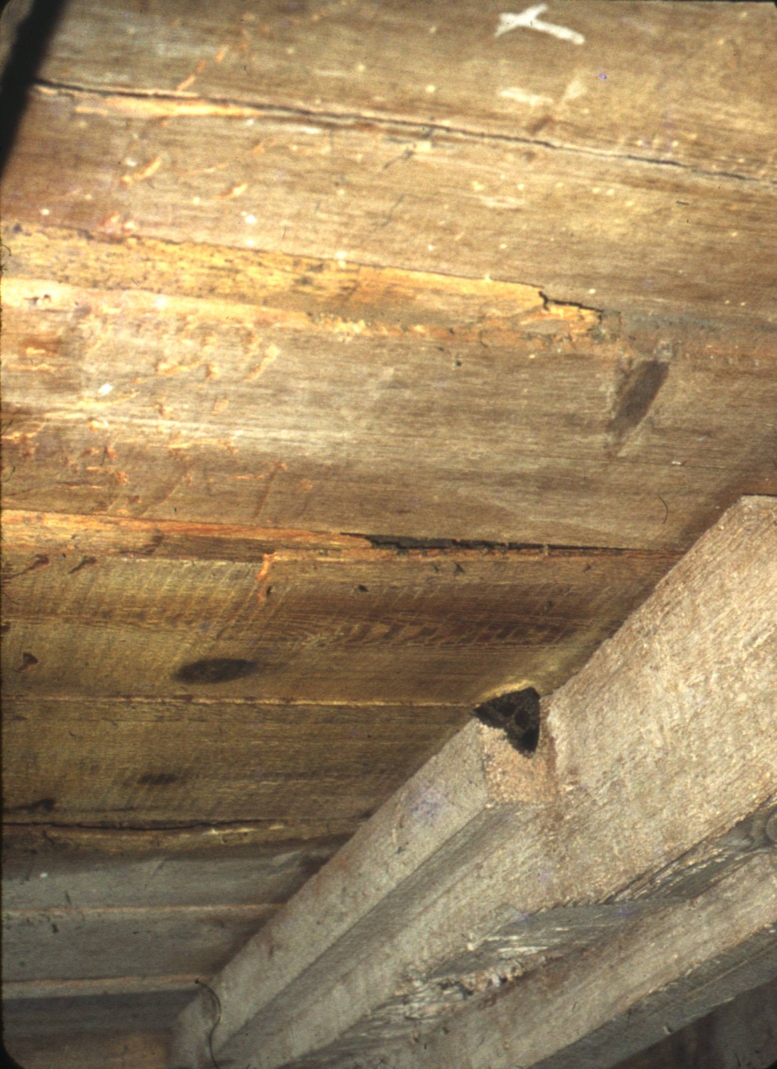
It would be a poorly-maintained mill where there was sufficient dust for a spark from the gears to cause an explosion. The photo shows the underside of the grinding area at Eling. Although the mill had ceased operation for some years, it had not been cleaned and there was little sign of flour dust hanging around. The flooring in flour mills had loose tongues between adjacent planks, drastically reducing the chance of flour falling through to the gear area. It was in the immediate enclosed area around the stones where the danger mainly lay.
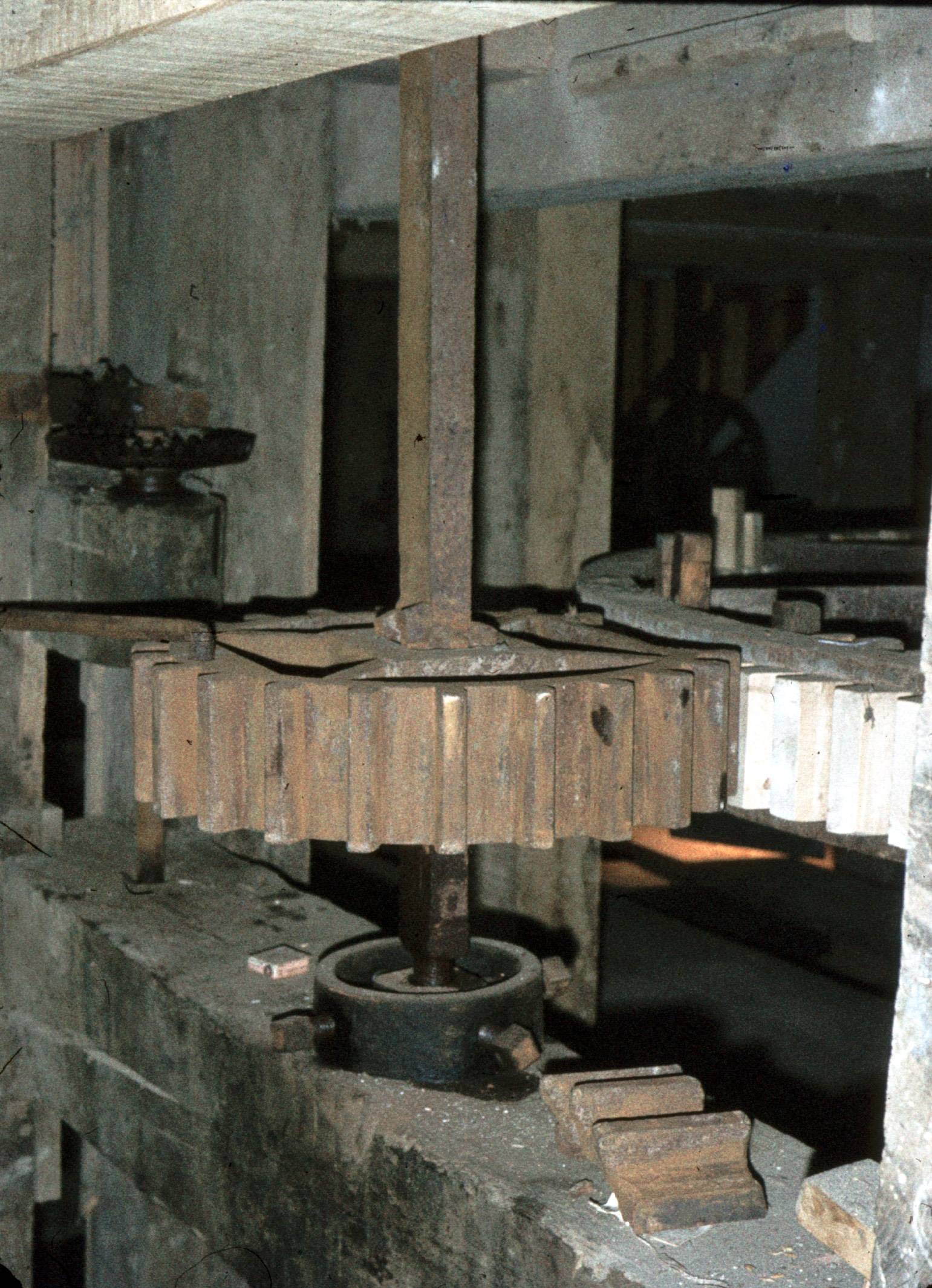
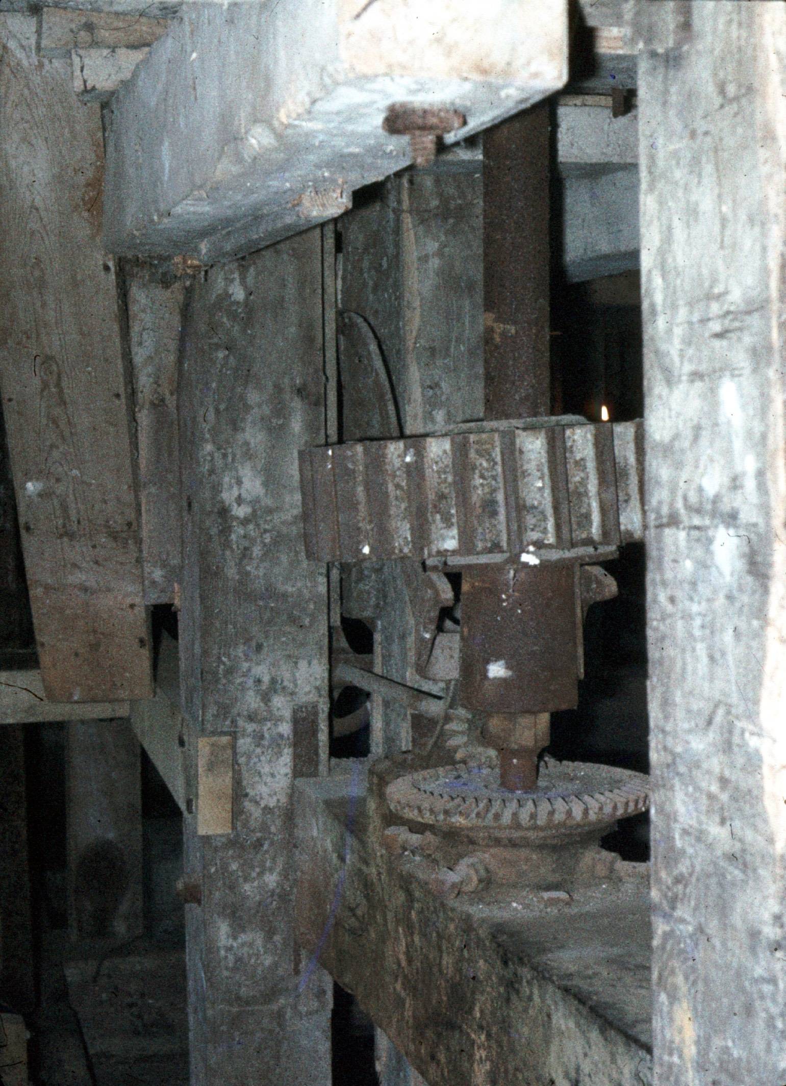
-
Wooden teeth were used because it was impossible to get teeth cast accurately enough to ensure that they meshed easily and quietly if both were iron. Apple is fine grained and tough, so made an excellent material for gear teeth. The photo below, of Eling Tide Mill in 1978, shows a typical set up, with the small cast iron gear driving the mill stone, and the larger gear with wooden teeth to drive it. The mesh was not exactly perfect by modern standards. This photo shows another method for raising the small millstone gear clear of the large drive gear with wooden teeth - the cast iron gear could rise and fall whilst still held by the vertical shaft - and at the bottom of that shaft the gears for raising and lowering it. They raised and lowered the millstone which revolved. The two millstones, one rotating and one stationary, touching whilst grinding was the main cause of explosions and fires in flour mills.
-
Fairbairn, Mills and Millwork, two vols. You should be able to download from Google, or Internet Archive. Just a quick look will tell you that it is a pretty extensive subject. I have a number of pdfs of books I have copied - probably most are now available to download - but can send you a selection by wetransfer.
-
I would be interested to see any archive material related to specific weir and water levels. I haven't found anything on the Rochdale, and those archives are much more extensive than most other canals. This is from the Engineer's Reports for the Lancaster Canal in Jan 1814: I wish to call the attention of the [page 199 begins] Committee to the manner of passing the Surplus Water at the Locks, that is, to convey the spare Water from the Blackburn Level to the Chorley Level. It is usual, in such cases, to pass the Water from one Pool to the other either by making a waste Weir in the form of a Culvert on the back side of the Lock Walls, or to provide for it by leaving an opening in the Masonry above the Sluices and carrying it through the Chamber of the Locks. The former is attended with a considerable expense, probably at each Lock not less than £60, the latter none at all. To this latter method it Is objectionable by some as a sediment in some degree is deposited in the Locks which must be removed from time to time as it happens. Where a strong body of Water becomes necessary to be forwarded from one Level to the other the former is certainly advisable and cannot be dispensed with, it is an operation that can be done after the Locks are finished was a little inconvenience except where there are Bridges at the tail of the Locks as that will be the case at Copthirst Lane. The provision should be made there on the back of the Walls, and the other to be done when the necessity of such conveyance appears. There is no immediate hurry for concluding upon this and the Committee may take some time to consider of it.
-
Then, when the canal is full, there will always be at least 2 inches water level difference across the top gate, making it very difficult to open by hand.
-
The following is extracted from my 2004 report on Rochdale Canal paddle gear. 7.4 Airholes One feature of the Rochdale Canal ground paddles was the use of airholes for water level control instead of byewashes. These are generally to be found on the Yorkshire side of the canal, and lock 39 may be the most westerly example. Excess water from the upper pool runs through the airhole and into the ground paddle sluice and then into the lock chamber. It should then run to waste through the bottom gate paddles. In the first Rochdale Canal Act a clause specifies that the bottom gate paddles should be left open after the lock has been used. Some people consider that this was related to the operation of airholes, but similar clauses appear in Acts for canals which did not have the airhole system, such as the Leeds & Liverpool Canal. More probably, it was included because lock walls were seen as a source of leakage as it was difficult to keep them watertight. This was certainly the case on the Rochdale where the puddle lining behind lock walls may only have been sufficient to preserve the water in the lower pool. Leakage from behind lock walls was a continual problem mentioned in the engineer’s reports, and the effects are still apparent today. With the chamber empty, the smaller upper gates would be less likely to leak excessively then the larger lower gates with the chamber full. The airhole system relies on the upper face of the bottom gate being used as the datum for the pool above the lock. This has been ignored in the reconstruction of some gates. Although byewashes are now installed, gate height is still an important factor in the efficient operation of locks when water is running to waste, and this is causing problems, particularly on the Manchester locks. There the top gates are higher than the bottom, making it impossible for water levels to become equal either side of the top gates when the upper pool is full. For efficient operation, the upper gates should be slightly higher than the airhole or byewash level; the lower gates should then be a couple of inches higher than the upper gates; and the waste weir an inch or so higher than the lower gates. If the lock is left empty, excess water will normally pass through the airholes. If the lock is full, then excess water passes over the lower gates allowing the upper gates to be opened without difficulty. Water flowing over the gates is kept to a minimum by any large excess being diverted over the waste weir into nearby water courses. Airholes seem to have been a feature of some canals built or influenced by Jessop. For example they were used on the Basingstoke, Cromford, Barnsley, Nottingham, Grand Junction and Grantham Canal for which he was engineer. Jessop also trained John Killaly in Ireland when he was working on the Grand Canal, and Killaly uses the system when he builds the Royal Canal extension. It was also used by Crosley Junior on the Lancaster Canal extension at Tewitfield, by Outram (associated with Jessop on the Cromford) on the Peak Forest, and by Rennie on the Kennet & Avon. There are detail variations between in the type of airholes used on individual canals. For instance, on the Peak Forest Canal there are airholes at both the upper and lower gates. The system may have problems when large volumes of water are being supplied to lower sections of the canal or during heavy rainfall on sections not fitted with sufficient waste weirs. In these cases, flooding can result from blockage of the relatively small airholes. Water will cascade over the gates, but in excessive amounts it may damage the structure of the lock tail. Byewashes were built around locks 6 and 7 following flood damage to the canal caused by heavy rain. Byewashes were also built around the Tewitfield Locks on the Lancaster Canal when they were closed to ensure that there was no unnecessary interruption to the supply from Killington Reservoir. Judging from the stonework, they were also fitted to the Peak Forest Canal locks sometime after they were built, perhaps in the late nineteenth century.

.jpg.166e92907ec203324367e6cdb593d2e7.jpg)