Jen-in-Wellies
Moderator-
Posts
6,958 -
Joined
-
Last visited
-
Days Won
32
Content Type
Profiles
Forums
Events
Gallery
Blogs
Store
Everything posted by Jen-in-Wellies
-
Having drunk tea in various parts of the world, including Tibetan style with Yak butter, I've found that Americans make the very worst. What can you expect from a country that started by throwing tea leaves in to cold salt water. Jen
-
More like rose tea.
-

What kind of fuse holder is this?
Jen-in-Wellies replied to BlueStringPudding's topic in Boat Equipment
There are mini blade fuses which, (surprise!) are smaller than standard blade fuses. Could it be a holder for one of these? There are also maxi blade fuses, which again look similar to standard ones, but I don't know how their size compares to standard ones as I've never used them. https://www.polevolt.co.uk/acatalog/Mini_Blade_Fuses.html Jen -
Mixing teas. A potentially very hazardous thing. In the kitchen of a bunk house we stayed in last year there was a packet of Yorkshire Tea, by Taylor's, a packet of Lancashire Tea, also made by Taylor's and a big tea pot. You can guess what comes next. What would be the result? What would the blast radius be? Would the crater be visible from space? Human sacrifice, cats and dogs living together, mass hysteria? Would the contradiction rip apart the fabric of space-time and consign the entire universe to oblivion? We survived and the brew went down well. Could it be that the leaves being confined within the bags prevented them from mixing with disastrous result? Or could it be that Taylor's of Harrogate put Lancashire on the packet of the same tea so they could sell them over the border. I see a scandal here more outrageous than even Dom in Barnard Castle. Jen
-
All that tea has done wonders for my complexion too. ?
-
Loose tea in a pot here. Suspect that the bag bit of tea bags is mostly plastic as they don't rot down when composted at all. Since tea is my drug of choice going to loose leaf is my bit for reducing plastic use. Tea strainers used to be rubbish when I was a little un and left you straining the leaves out with your teeth. You can now get very fine mesh non-rubbish tea strainers. Jen ?
-
That sounds a good way of getting an absolute reading. There are various in tank senders around which would work well if the tank is accessible for fitting. If not, then it may be possible to fit a sender in a remote vertical pipe, T'd in to the pipe between tank and pump. The level in this, if it is open vented, will match that in the tank. Similar to the sight gauges that people sometimes make, but with remote reading to a gauge. It wouldn't be accurate when the pump runs due to the low pressure it puts on that pipe, but otherwise would be pretty good. Jen
-
What capacity shore bollard are you connected to? 16 (or lower), or 32A? The sockets on 32A shore bollards are different from 16A ones. What size inverter do you have? A 3KW inverter can output a maximum of 12.5A at 240V, so 16A rated things will be fine. Over specified fittings for the current being handled are fine. Under specified ones are not. Jen
-
An easy and cheap way to do it without risking accidentally connecting both inverter and mains outputs is to use the usual 16A plugs and sockets. Have one of these as the input to the consumer unit https://www.screwfix.com/p/abb-16a-2p-e-surface-plug-250v/6490f Then have the output from the inverter and the mains coming in from the shore line each on one of these and plug the appropriate one in to the socket above. https://www.screwfix.com/p/abb-16a-2p-e-connector-250v/2264x Similar effect to the Break Before Make switch that @BEngo describes, but cheaper. Only one power source can be connected to the boat at any time. Having both shore and inverter mains meeting will release the expensive magic smoke.
-
I've done a bit of reading on power minimisation, but need to do a lot more. The flow sensor is on an interrupt pin, so this will hopefully be possible to use to wake it up when water flow is happening. The rest of the time it can be asleep as the servo won't be moving and nothing will be happening. The flow meter is in the outlet from the tank. Either before, or after the pump. It doesn't detect tank filling at all. You tell it the tank is full by hitting the reset button. Jen
-
I'm not planning to make any more, but I've hopefully put enough detail in this thread that someone else could. As Arduino projects go it is pretty simple. Only three inputs and two outputs. I've tried reading the Lithium battery threads, but it makes my head hurt. Jen
-
Replacing Rinse Out Cap - Help!
Jen-in-Wellies replied to Gabby_Boating's topic in Boat Building & Maintenance
So it is OK to put diesel on the pump out tank access! Just so long as the thief doesn't spot the real diesel filler. ? -
The Arduino IDE's compiler isn't quite that bad. It will point you to roughly what line it sees a problem. OK the actual problem might be in a previous line that then makes the line shown invalid, but usually enough of a clue to fix after some head scratching. Jen
-
If it is a junction box designed for normal domestic solid cored twin and earth, then boot lace ferrules on the multi strand wire you should be using is a good idea. Jen
-
Replacing Rinse Out Cap - Help!
Jen-in-Wellies replied to Gabby_Boating's topic in Boat Building & Maintenance
Whatever it is, the port needs to be labelled, either on the cap, or nearby with what it is. Having the wrong label is a BSS fail, so putting Diesel on the pump out point is a no-no, despite the karma for diesel thieves. Jen -
Agreed. This is why there is a reset button to take it all back to a known state (Full 100%) every time the tank is refilled. Saves it getting too out of step with reality. No. Yep. C takes no prisoners with mistakes. Looking in to and minimising current draw is the next step in the project. Jen
-
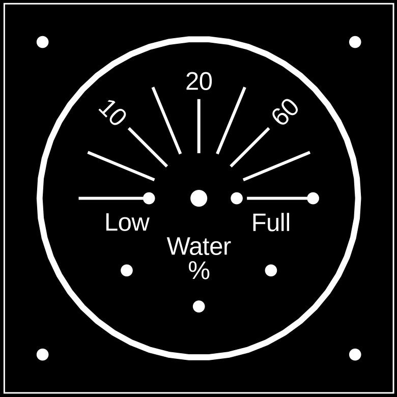
Hardware. The needle that is used to indicate tank level is made from one of the actuator horns that are typically included when you buy an SG90 servo. This has a series of holes in it for fitting actuating wires that, for example, in a model aeroplane, would go to a control surface. These are filled in with araldite. Once the araldite is dry, the needle can be filed to a point. I painted them red with nail polish once they were the final shape. The centres are splined to fit on to the splined output shaft of the servo. If the splines mean the needle isn't exactly set at zero when at 100%, then the servoOffset constant in the sketch can be used to trim it to zero. The dial face on these was made from a piece of 3mm thick plywood, 65 x 65mm thick. The gauge face was designed in OpenSCAD to get the dial marks and holes in the correct positions. If you don't use OpenSCAD, then it can be designed in any Cad program you are used to. I have included the openSCad at the bottom. The exported design was imported in to a graphics program and turned in to a black and white print that was printed out on to thick paper. If you save the picture below it should print out at the correct size. The printed dial was then glued with wood glue to the plywood. Holes and openings were drilled for the servo, light sensor, LED, reset button and fixing holes. The servo is held in with some M2 press fit threaded inserts pushed in to the ply and M2 10mm long bots. The paper dial is protected by coating it either with clear nail varnish (the first one I made), or with a clear spray varnish (the second). The electronics are built up on to a bit of vero strip board. It is all 0.1" pitch, including the Arduino Nano, so not difficult to solder together. For the lead between the flow rate sender and the Arduino is done with some four core twisted pair wire, with the signal and ground using one twisted pair and the +5V the other pair. This seems to work OK over a couple of metres, but at some point will no doubt start to pick up interference, or not work reliably, so there is a maximum distance that it will cover. I just don't know what that is yet! The cheaper Arduino Nano clones can be had for a few quid. Sometimes these need USB drivers installed on the laptop, or may not have a boot loader set up on the Arduino, so it pays to shop around and maybe not go for the cheapest Ebay ones. The ones I got were in the UK and have worked well, but needed the aforementioned USB drivers installed to be able to talk with them. Jen OpenSCad file below if anyone wants to customise it. Give it an .scad extension to use. //Dial design for water gauge $fn=50; overallSize = 65; dialRadius = 26; fixingDia = 2; //full size 3 textRadius = 18; fontSize = 3; markLength = 9; markWidth = 0.5; markDisplace = 12; bigmarkLength = 12; bigmarkWidth = 0.5; bigmarkDisplace = 14; pointerLength = 16; pointerWidth = 5; pointerAngle = 30; font = "Liberation Sans"; //square([50,11.8], center=true); //servo body //Pointer /*rotate([0,0,pointerAngle]){ translate([pointerLength/2,0,0]){ square([pointerLength,pointerWidth], center=true); } }*/ //dial outline difference(){ circle(dialRadius+1); circle(dialRadius); } //overall outline difference(){ square([overallSize,overallSize], center=true); square([overallSize-0.5,overallSize-0.5], center = true); } //Fixing Holes translate([dialRadius,dialRadius,0]){ circle(d=fixingDia); } translate([dialRadius,-dialRadius,0]){ circle(d=fixingDia); } translate([-dialRadius,dialRadius,0]){ circle(d=fixingDia); } translate([-dialRadius,-dialRadius,0]){ circle(d=fixingDia); } //Legend translate([0,-markDisplace*2/3,0]){ text("Water", font = font, size = fontSize, valign = "center", halign = "center"); } translate([0,-markDisplace,0]){ text("%", font = font, size = fontSize, valign = "center", halign = "center"); } //Drill marks for servo, LED, phototransistor and push button. translate([0,0,0]){ circle(d=2.8); //Spindle. Full size 11 } translate([6.3,0,0]){ circle(d=2); //gear. Full size 5 } /*translate([6.3-2.5,0,0]){ square([5,5],center=true); //gear }*/ translate([-markDisplace, -markDisplace,0]){ circle(d=2); // Low water LED. Full size 11 } translate([markDisplace, -markDisplace,0]){ circle(d=2); //Full reset button. Full size 11 } translate([0, -markDisplace*3/2,0]){ circle(d=2); //phototransistor. Full size 4.3 } translate([-8.3,0,0]){ circle(d=2); } translate([19,0,0]){ circle(d=2); } //Text for LED and push button translate([-markDisplace, -markDisplace/3,0]){ text("Low", font = font, size = fontSize, valign = "center", halign = "center"); } translate([markDisplace, -markDisplace/3,0]){ text("Full", font = font, size = fontSize, valign = "center", halign = "center"); } //Text and marks for needle pointer. rotate([0,0,0]){ translate([bigmarkDisplace,0,0]){ square([bigmarkLength,bigmarkWidth], center = true); } /*translate([textRadius,0,0]){ text("F", font = font, size = fontSize, valign = "center"); }*/ } rotate([0,0,0]){ translate([0,markDisplace,0]){ square([markWidth,markLength], center = true); } translate([0,textRadius,0]){ text("20", font = font, size = fontSize, valign = "bottom", halign = "center"); } } rotate([0,0,135]){ translate([markDisplace,0,0]){ square([markLength,markWidth], center = true); } translate([textRadius,0,0]){ rotate([0,0,180]){ text("10", font = font, size = fontSize, valign = "center", halign = "right"); } } } rotate([0,0,45]){ translate([markDisplace,0,0]){ square([markLength,markWidth], center = true); } translate([textRadius,0,0]){ text("60", font = font, size = fontSize, valign = "center"); } } rotate([0,0,180]){ translate([bigmarkDisplace,0,0]){ square([bigmarkLength,bigmarkWidth], center = true); } } /*translate([-textRadius,0,0]){ text("E", font = font, size = fontSize, valign = "center", halign = "right"); }*/ //Bigmarks insterstitial to numbers. rotate([0,0,22.5]){ translate([bigmarkDisplace,0,0]){ square([bigmarkLength,bigmarkWidth], center = true); } } rotate([0,0,22.5+45]){ translate([bigmarkDisplace,0,0]){ square([bigmarkLength,bigmarkWidth], center = true); } } rotate([0,0,22.5+90]){ translate([bigmarkDisplace,0,0]){ square([bigmarkLength,bigmarkWidth], center = true); } } rotate([0,0,22.5+135]){ translate([bigmarkDisplace,0,0]){ square([bigmarkLength,bigmarkWidth], center = true); } }

-
You didn't get to the punch line at }.
-
Programming. There are two Arduino sketches here. First thing we need to find out is how much water the tank contains. The first sketch displays how much water has flown through the sensor. Fill up the tank, connect an Arduino to the flow meter, load this sketch and have a serial monitor open on your laptop. Open up the taps on the boat and wait till the tank empties. Read the tankUsed from the serial monitor. This, minus a few percent safety margin will become the tankFull constant in the water gauge sketch. Tank calibration sketch. #include <FlowMeter.h> // https://github.com/sekdiy/FlowMeter //Sensor properties for YF-S201B flow meter FlowSensorProperties YF_S201B = {30.0f, 7.5f, {1, 1, 1, 1, 1, 1, 1, 1, 1, 1}}; // connect a YF-S201B flow meter to interrupt pin 2. FlowMeter Meter1 = FlowMeter(2, YF_S201B); // set the measurement update period to 1s (1000 ms) const unsigned long period = 2000; float tankUsed = 0; // define an 'interrupt service handler' (ISR) void Meter1ISR() { // let our flow meter count the pulses Meter1.count(); } void setup() { // prepare serial communication Serial.begin(9600); // enable a call to the 'interrupt service handler' (ISR) on every rising edge at the interrupt pin attachInterrupt(INT0, Meter1ISR, RISING); // sometimes initializing the gear generates some pulses that we should ignore Meter1.reset(); } void loop() { // wait between output updates delay(period); // process the (possibly) counted ticks Meter1.tick(period); tankUsed = Meter1.getTotalVolume(); // output some measurement result Serial.println("Currently " + String(Meter1.getCurrentFlowrate()) + " l/min, " + String(Meter1.getTotalVolume())+ " l total."); Serial.println("Currently " + String(Meter1.getTotalVolume())+ " l total."); Serial.print("tankUsed "); Serial.println(tankUsed); } The water tank gauge sketch follows. It will need customising with your own tank capacity (tankFull) and servoCal and servoOffset figures. SG90 servos vary from one to the next, so you'll need to experiment with these so zero and full match the needle positions at 0 and 180 degrees. /*A water meter for boats. Written by Jen-in-Wellies. May 2020. Uses a YF-S201B flow meter at the water pump inlet to track water tank contents. Indicates contents using a servo as an "analogue" dial. Low level warning LED. If this is used in a bedroom, a BP103 phototransistor can measure the ambient light level and disable the low level warning LED at night. */ #include <FlowMeter.h> // https://github.com/sekdiy/FlowMeter FlowSensorProperties YF_S201B = {30.0f, 7.5f, {1, 1, 1, 1, 1, 1, 1, 1, 1, 1}}; FlowMeter Meter1 = FlowMeter(2, YF_S201B); void Meter1ISR() { // let the flow meter count the pulses Meter1.count(); } #include <Servo.h> // Standard servo library. Servo myservo; #include <EEPROM.h> //Standard EEPROM Library to store water level over power downs and resets. //Pins. const byte lowPin = 5; //Low water warning LED pin const byte resetPin = 7; //Reset water level to 100% const byte servoPin = 9; //output pin for servo. const int photoPin = A0; //input pin from BP103 phototransistor. //Customise these values to the boat on which it is installed. const int tankFull = 64; // Tank capacity in litres. const float servoCal = 0.96; // Compensation to get 180 degrees programmed servo rotation to equal 180 degrees in real life. const byte servoOffset = 0; //The c in y=mx+c. Zero the servo angle at 100% //constants and variables. const byte lowLevel = 10; //Low water level % for warning LED to light. float tankStored; //Stored tank level in EEPROM const byte tankAddress = 0; //Address used on EEPROM float tankUsed; //Current cumulative water used in litres. float tankPercent; //Percentage tank water level. float servoAngle; //Calculated angle to swing the servo. float currentVolume = 0; //Current volume passed by sender. const unsigned long time1 = 2000L; //loop time (ms) unsigned long timer1 = 0L; //count for the needle movement loop const unsigned long time2 = 300000L; //time for the loop copying current tank level to EEPROM (ms). unsigned long timer2 = 0L; //count for the tank level EEPROM loop. unsigned long now = 0L; //time now. const int photoThreshold = 50; //Ambient light level at which the low water LED is switched on, or off. int photoLevel; // ambient light level. const byte deBug = 1; //Set to 1 to send serial debug data over USB. 0 otherwise. const byte zeroEEPROM = 1; //Reset the eeprom stored tank used value to zero by setting this to zero. Once only on new Arduino, then set to 1. void setup() { // put your setup code here, to run once: //Define digital pins. pinMode(lowPin, OUTPUT); pinMode(resetPin, INPUT_PULLUP); //Water Meter. Enable a call to the 'interrupt service handler' (ISR) on every rising edge at the interrupt pin attachInterrupt(INT0, Meter1ISR, RISING); // sometimes initializing the gear generates some pulses that we should ignore Meter1.reset(); //Flash low level LED a couple of times. digitalWrite(lowPin, LOW); //LED on delay(500); digitalWrite(lowPin, HIGH); //LED off delay(500); digitalWrite(lowPin, LOW); //LED on delay(500); digitalWrite(lowPin, HIGH); //LED off //Attach servo to pin and move to 0 degrees (full) myservo.attach(servoPin); timer1 = millis(); timer2 = millis(); //Set EEPROM stored tank used Normally not used. Useful to set up a new Arduino. Zero (0.00), or carry over value from old Uno. if (zeroEEPROM == 0) { EEPROM.put(tankAddress, 0.0); } //ReadEEPROM for stored tank used and set initial tankUsed to this values. EEPROM.get(tankAddress, tankStored); tankUsed = tankStored; if (deBug == 1) { Serial.begin(9600); //debug } } void loop() { // put your main code here, to run repeatedly: //Water Meter. Check if water tank level reset button is pressed. If so, then set tankUsed and EEPROM stored value to zero. //Do once only per press by checking if tankUsed has been reset, to prevent multiple EEPROM writes and wearing out. if ((digitalRead(resetPin) == LOW) && (tankUsed != 0.0)) { tankUsed = 0.0; EEPROM.put(tankAddress, tankUsed); Meter1.reset(); //Reset water meter. } now = millis(); //Current time for the conditional loops timer1 and timer 2 //Check every time2 interval and write tankUsed to tankStored if they are different. //Saves water level over resets. A longer time than time1 to save wear and tear on EEPROM. if ((now - timer2) > time2) { EEPROM.get(tankAddress, tankStored); //get current stored tank level. if (tankUsed != tankStored) { EEPROM.put(tankAddress, tankUsed); } timer2 = now; } //Check every time1 interval to see how much water has been used. Set servo to new tank level. if ((now - timer1) > time1) { //Check water usage over time1 cycle and update tankUsed and tankPercent. Meter1.tick(now - timer1); currentVolume = Meter1.getCurrentVolume(); if (currentVolume > 0) { tankUsed = tankUsed + currentVolume; //Add amount measured since last loop } tankPercent = 100 * (tankFull - tankUsed) / tankFull; if (tankPercent < 0) tankPercent = 0.00; //No negative tankPercent. //Calculate servo angles. O to 20% takes up half the deflection. 20 to 100% the other half. if (tankPercent >= 20) { servoAngle = 180 - ((tankPercent * 1.125) + 67.5); } else { servoAngle = 180 - (tankPercent * 4.5); } myservo.write((servoAngle * servoCal) + servoOffset); //Use servoCal and servoOffset to calibrate servo angle swing for individual servo. delay(15); photoLevel = analogRead(photoPin); //Read the light level. if a phototransistor is fitted. delay(15); //Light the low level warning LED if the tank level is low and it isn't dark. if ((tankPercent <= lowLevel) && (photoLevel > photoThreshold)) { digitalWrite(lowPin, LOW); } else { digitalWrite(lowPin, HIGH); } timer1 = now; //Debug if (deBug == 1) { Serial.println("DEBUG"); //Serial.print("time stamp "); //Serial.println(millis()); Serial.print("now "); Serial.println(now); //Serial.print("timer1 "); //Serial.println(timer1); //Serial.print("timer2 "); //Serial.println(timer2); //Serial.print("photoLevel "); //Serial.println(photoLevel); Serial.print("Now - timer1 "); Serial.println(now - timer1); Serial.print("now - timer2 "); Serial.println(now - timer2); Serial.print("reset button "); if (digitalRead(resetPin) == LOW) { Serial.println("Pressed"); } else { Serial.println("Open"); } Serial.print("tankStored "); Serial.println(EEPROM.get(tankAddress, tankStored)); Serial.print("tankUsed "); Serial.println(tankUsed); Serial.print("tank percent "); Serial.println(tankPercent); Serial.print("servo angle "); Serial.println(servoAngle); Serial.print("servoAngle * servoCal + servoOffset"); Serial.println((servoAngle * servoCal) + servoOffset); } } }
-
Simple is good. There are lots of ways of doing this. Got away for years with knowing that a tank lasted me about a week, so Saturday was fill up day. Right at the start of owning this boat I made a transparent sight gauge. This worked well, but went green from algae, so I removed it. Yuck!
-
That's it. You need to remember to press the button when you fill the tank, but it is an easy habit to get in to. The electronics. The gauges are powered from the same supply as the water pump. There is a risk therefore of voltage spikes. I used an 18V automotive grade metal oxide varistor across the power input lines to dump any spikes. There is a self resetting fuse to protect the wiring in to the gauge. The gauge runs on 5V, so I used a buck voltage converter to drop the 12 to 14V in. Arduino PLC's do have a built in voltage regulator, but this is quite wasteful of power at higher voltages, so I fed the Arduino straight in to the 5V pin from a more efficient converter. SG90 servos go from 0 to 180 degrees. Actually a bit more than 180 degrees, so you need a bit of calibration sums in the code so the position matches where you think it should be. They are cheap as chips on ebay, around £1 each if ordered in bulk. The ambient light sensor is a BP103 phototransistor. The same type I used on the solar thermal system. I bought a pack of five last year, so had several left over. The base pin is left unconnected. If you don't want to disable the low warning LED at night, then either remove it from the circuit and sketch, or put a high value resistor to pull A0 up to 5V to simulate daytime all day round. The circuit diagram is below. Jen
-
Last year I added a water tank level meter to the solar hot water control system I'd built for my boat. This used a cheap (around £6) flow sensor fitted between the sediment filter and the water pump. The sensor measured the volume passing and the Arduino logic controller calculated how much water was left in the tank. This was displayed as a tank percent full on a set of LED's. This has been working very reliably since. A couple of neighbouring boaters on the mooring have asked for something similar for their boats. The water tank meters I have built for them use the same model of flow meter, a YFS201B. This time the PLC is a smaller Arduino Nano, rather than an Uno. The level is indicated using an SG90 servo motor to turn a needle, giving an analogue like gauge. The first one is now installed and working. The gauge for the second boat is ready to fit. It is wet and miserable outside today, so I'm writing up a bit about them. First off, a short video of the first gauge being tested. The sketch is simulating 1 litre of water being drawn from a 70l tank every few seconds. The first half of the gauges range covers from 100% full to 20%. The second half covers from 20% to empty. A warning LED lights from 10% down. We are more interested in what the gauge is showing when it is nearly empty, hence the expansion of the range below 20%. The electronics for the second gauge can be seen on the right of the video. Version 2 includes a light sensor. This gauge is going to be in a bedroom and the sensor will disable the bright warning LED at night so the owners can sleep. Total material costs for each gauge comes to around £25, depending on where you get them. More to follow... Jen
-
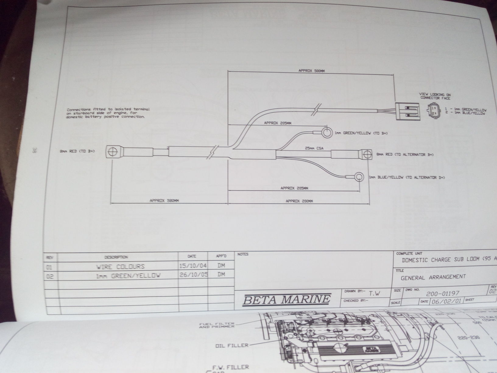
Looking at the wiring diagrams, the domestic alternator warning lamp signal doesn't go through the main multipin plug sockets, but a separate set of 2 pin plug/sockets. My mistake! One at the engine end, one at the panel. The wires in to them are Green/Yellow and Blue/Yellow. The Blue/Yellow being the alternator warning and field energisation wire. It stays this colour from the bulb holder to the alternator through two sets of two pin plugs and sockets. One by the panel, one by the engine. Jen
-
The wire on the domestic alternator that goes to the D alternator warning light will be blue with a yellow stripe. This connects to the alternator D+. This may be hard to identify due to Beta's unfortunate habit of spraying everything green. There is another plug/socket that is in the way of this wire before it gets to the famously dodgy multipin plug, so this is another one to check. See the picture below of the loom for the domestic alternator from my manual. Also the wiring for the back of the posh delux control panel and the dodgy multipin plugs at the engine and panel ends. Jen
-
My Beta 43 control panel, the simple one without oil pressure and water temperature gauges, has two alternator warning lights. The engine alternator light has a picture of a battery as an icon. The domestic alternator icon is the same with a capital D in the middle. This should light when the panel is powered up and the engine is stopped. Go out when engine running. This light is wired Ignition 12V on, via the bulb, rubbish connector block, to the alternator. Jen Edited: Just checked the Beta manual and the Gucci control panel with the extra gauges still has the two alternator warning lights.