Emma b
-
Posts
41 -
Joined
-
Last visited
Recent Profile Visitors
1,277 profile views


Emma b's Achievements
")
Engager (3/12)
4
Reputation
-
Victron multiplus case earth bonding?
Emma b replied to Emma b's topic in Boat Building & Maintenance
Hi elastic, Thanks for that and yes good to know. All has been fine since so good news! -
Victron multiplus case earth bonding?
Emma b replied to Emma b's topic in Boat Building & Maintenance
Right Gents. I disconnected the chassis earth and there is continuity present between the Victron case and the hull (earth) when the Victron is operating via the shore line (on charge only) and when disconnected from the shore line (invertor switch selected ) so looks like no need for that extra earth I fitted! Hopefully that is one query solved many thanks again. Simon -
Victron multiplus case earth bonding?
Emma b replied to Emma b's topic in Boat Building & Maintenance
Thanks for this gents it is much appreciated. I meant the input wiring not shoreline as you picked up earlier. I could either/also take an earth tapping from the boat side of the galvanic isolator to the hull easily too if appropriate. Again many thanks and I look forward to clarification Simon -
Victron multiplus case earth bonding?
Emma b replied to Emma b's topic in Boat Building & Maintenance
Hi Rob just to confirm the earth from the shore line and after the galvanic isolator goes to the earth bus inside the consumer unit and then another earth runs from the same earth bus bar to the hull. In addition I earthed the Victron casing as well to the hull. The casing wasn't earthed before. Regards Simon -
Victron multiplus case earth bonding?
Emma b replied to Emma b's topic in Boat Building & Maintenance
Thank you for that clear explanation nick. I will remove the "additional " earth bond I fitted and shall sleep easier tonight. Simon -
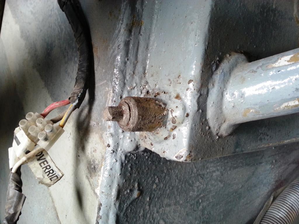
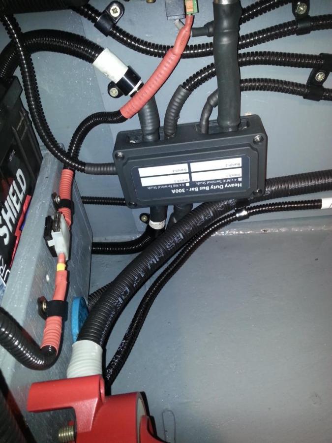
Hi could anyone please clarify whether or not my multiplus casing should be bonded to the hull or not please? There is a hull earth from the 240 consumer unit and a galvanic isolator is fitted . It didn't have a case earth but I fitted one recently. The reason for asking is when, inadvertently I glanced a metal caged lead light on the battery positive terminal, I got an arc which surprised me. Simon
-
I have considered that Tony. We completely drained and cleaned the tank out this summer. It took some doing and was a breakdown waiting to happen I can assure you. Going along the preventive route and as part of that have fitted a drain to the tank. There are images in a recent posting of mine. We now fill the main and front (new stainless steel which feeds the bubble stove) via a rig set up with a fuel filter and water trap filter bowel out of new jerry cans to try to prevent contamination. So your idea may be simplier and as useful I'll have a think Many thanks Simon
-
Thanks Tony I'll work on it and let you know. Re the pick up the original one fitted is about an inch from the tank bottom. The way I understand it works is the 'cleaning' mode is used with the engine not running. There are valves and an electric pump supplied to isolate the engine when vleaning via the electric pump Simon
-
Hi All Am about to refit new fuel lines and diesel fuel filter housing and a fuel guard filter kit. I want to incorporate the 12 Volt pump which allows the fuel to be cleaned/recirculated. Question is does anyone have any images of the fuel guard system fitted to their boat to give me a few ideas of a suitable location etc? Trad boat with fuel tank unions top right hand side of tank and primary fuel filters mounted on left hand swim looking at the stern. Hope this makes sense Simon
-
Hi it's not self bleeding as such but simply a valve which I got from Pirtek
-
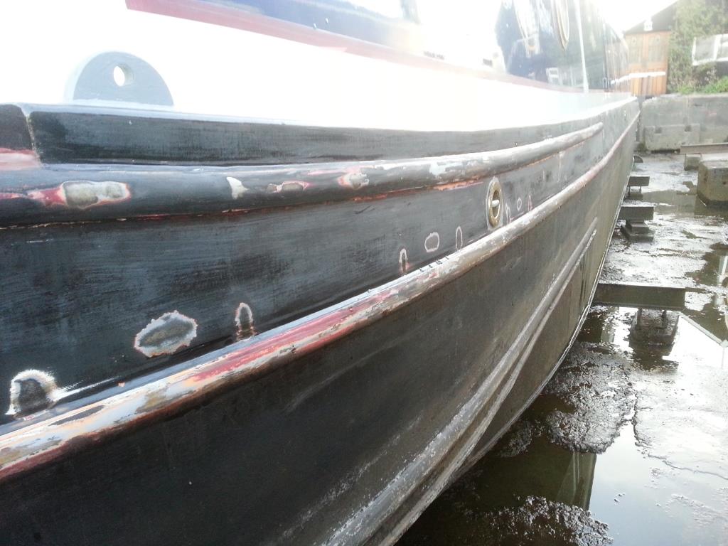
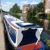
Has been a busy year or so but thought the images shown may give ideas if appropriate. The Ansa pins are probably the most useful thing added, The claw lock on the back doors replaced a ropy old welded shackle. The rest fairly self explanatory I think Kind regards Sim on Simon

-
We have this system and can concur with the other comments although is better since the muck was cleared out as shown!
-
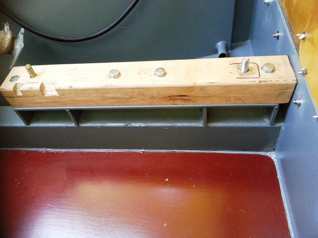
Another 'work in progress' post but engine in on new oak beams. Thanks for the thoughts given albeit sometime ago but the images may be interesting. All of the mounts were repaired by re-drilling them after welding them up. Luckily I obtained some technical drawings which gave me the dimensions including fore to aft mounting center holes @ 22 3/32" and side to side 9" from the center line left and right. i also altered the original top bearers by extending them to run the full length of the engine. Regards Simon
-
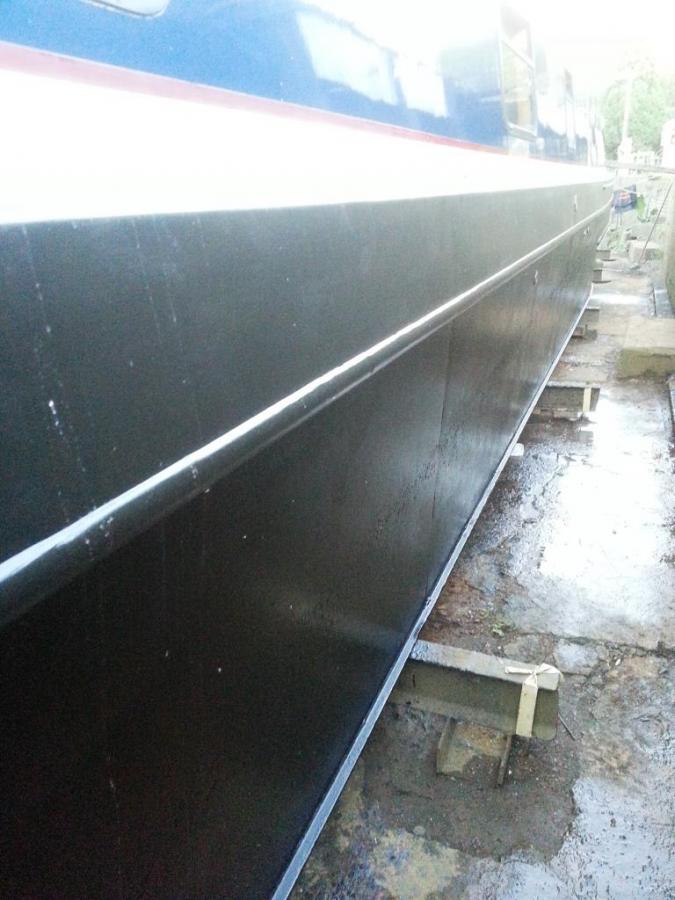
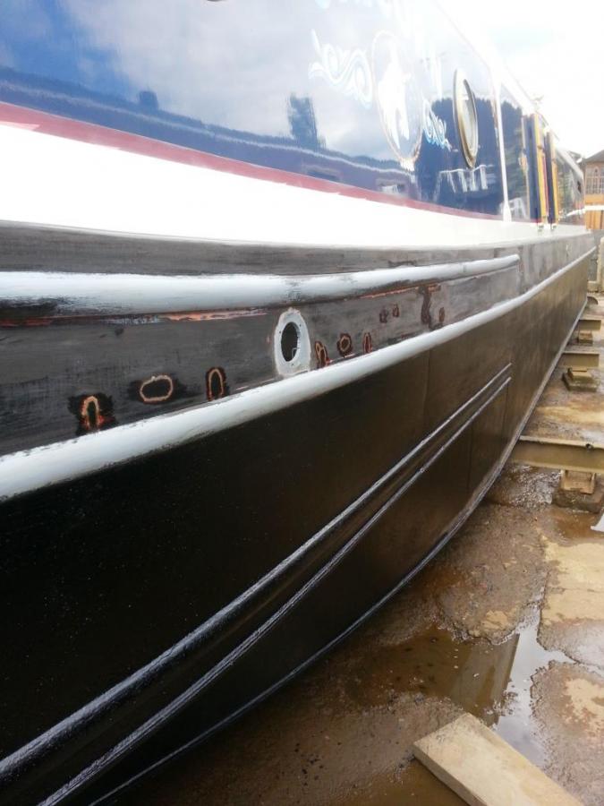
Been a while but to be fair the Keel Black went on well, dried easily and doesn't seem to of fallen off yet (been 5 months) but time will tell
-
Hi All, I have (hopefully) attached a few images showing the wiring Regards Simon