nicknorman
Patron-
Posts
22,144 -
Joined
-
Last visited
-
Days Won
119
Content Type
Profiles
Forums
Events
Gallery
Blogs
Store
Everything posted by nicknorman
-
Lady M is correct. The GSIUR specifically exempts leisure (non-residential) boats from itself.
-
The only surprising thing about that story is that you omitted to accidentally spill the contents of your cassette on his boat. Or maybe you did but don't like to admit it?😁 Obviously some historic boaters are nice people and some are not. It is hard to know if the balance is worse for HBs than for boats in general, but I think the sheer bulk and slightly intimidating appearance of eg a Large Woolwich means that any transgressions are more memorable. There is perhaps a tendency for HB owners to think it is clever to act like it is 100 years ago in terms of how they treat the infrastructure, but often this goes wrong so it is a good source of amusement!
-
Well to be fair to Lady M the “lock landing” outside the Greyhound is very recent. There is plenty of scope for getting off a boat elsewhere in the vicinity. So if someone wanted to moor there it wouldn’t exercise me too much. I wouldn’t moor there myself, but mainly due to the risk of incompetent boaters T boning me as they fail to negotiate the corner!
-
I answered that in the second post! If the cables are inside trunking etc then there is no minimum proximity to gas pipe. And actually a since it is artic flex ie each conductor is insulated, and then it overall sheathed, this is probably good enough even if not in trunking (but I would still run it inside trunking).
-
I think motorway service stations are a bit different because the catering is provided by other businesses and the seating is often not particularly linked to any one business. Anyway, the point of a motorway service station is to provide a service, eg it is quite OK to use the toilet without buying anything. This will be enshrined in the original permission to build the service station. Your addition of the £35 suggests this happened to you, but I think that is abnormal for a UK motorway service station
-
You may well be right in the case of a proper posh restaurant, however most “restaurants” are chains, and I bet the the computer says no if the minimum wage staff ask it.
-
Yes.
-
I suppose it is a little bit like going into a pub but taking in your own beer to drink. It wouldn't seem unreasonable for the publican to object.
-

Cable run size for water tank sensor
nicknorman replied to TandC's topic in Boat Building & Maintenance
12v and 240 ohms is 0.05A so I think 1.5mm^2 will be fine. -
running wiring next to polystyrene
nicknorman replied to Hannah and Jay's topic in Boat Building & Maintenance
If it ain't broke... As you say, the problem really only arises if you try to bend the cable. Left alone it will probably be OK. And if not, provided the circuits are properly fused, the worst that can happen is that some service stops working. -
Unfortunately it is their land and their marina, they can say who is allowed to enter their property and under what terms. So there is no legal recourse. The recourse is to cough up, moor elsewhere, or as said take the boat out of the marina for the work to be done. That latter could be a bit of a problem if mains power is needed I suppose. But anyway, if there is lots of hammering, grinding, drilling, sawing etc then it is only courteous to other marina users to take it out of earshot.
-
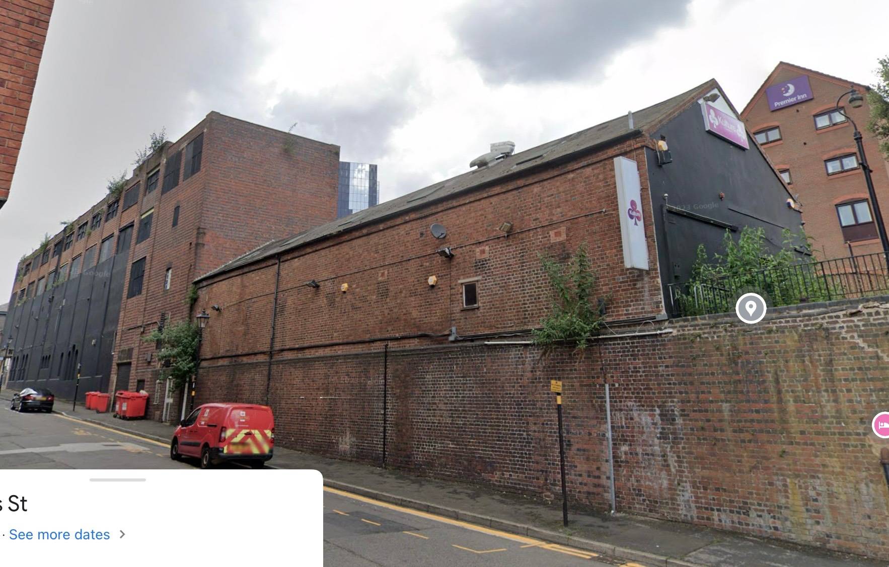
…A view from quite a while ago! It looks like this now. Surely the stables is just a shell with nothing of interest inside? The round house was well worth preserving but this doesn’t seem to me to have much merit. I think it is important to preserve some heritage, but also that one should pick one’s battles carefully. If every change is objected to, that voice becomes meaningless.

-
It stopped because the surface charge effect kept the battery voltage higher than the float voltage for a short time. When a charger is disconnected, the battery voltage doesn’t instantly drop to the rested fully charged voltage of around 12.8v, it subsides slowly as the surface charge effect dissipates. When the natural voltage of the battery is above float voltage, it won’t charge. Charging will resume once the surface charge effect dissipates and the natural voltage falls below the set float voltage.
-
Yes try 15A for now. Adaptive is definitely a fudge, “fixed with tail current” is a fudge if the system is not measuring actual battery current. As I said, the ideal way is fixed with tail current using battery current, but I appreciate the world is not always ideal!
-
Therein is the difficulty with not actually using battery current to trigger float, you have to fudge it! If that is going to be your regime every day, then it is OK, but presumably this won’t be the situation every day? You need a day off / go shopping etc! I would look at the permanent drains which would exclude the fridge, since that is sometimes on and sometimes off. It could only prolong the absorption time by the time the fridge is on until the thermostat clicks off which is probably no more than 15 mins or so. Your drain into the boat is 11A at the moment. If the fridge is running then I’d take off 3A for that. And add 4A for the tail current (rather than 2A, see above) making it 15A if fridge not running or 12 if it is. But if you are not working from home the system is going to go to float early because most of the 11A boat drain will be turned off.
-
This presumes that everyone only cruises during “office hours” which is incorrect. Especially in winter when it gets dark very early, just because it is dark doesn’t mean it’s ok to moor on services/lock landings etc. At night it is even more problematic to find such things blocked by moored boats. Anyway, it is contrary to the “rules” so why do historic boat owners think they are exempt? What would happen if everyone did it?
-
Looking back at what you said earlier - 450Ah battery - I think 2A tail current is rather low as it corresponds to 0.5% of capacity. The current will eventually get that low but it will take a long time and maybe not within the available solar charge time. You will have a long absorption duration at 14.8v and it will use more water. I would suggest around 1 % of capacity, ie say 4A tail current setting. But you can suck it and see of course.
-
So you think it is ok to moor on a water point/services/lock landing, and people shouldn’t object to it? Are you a historic boat owner by any chance?
-
Jaguar.
-
Well yes that is when it is relevant to terminating the absorption phase and switching the solar to float. But that is the “ideal” way of doing it, probably your scheme will work adequately especially if you add an appropriate amount to the tail current setting for any permanently-on boat loads eg an inverter.
-
Ok but I think this works because you have Li batteries. Mike has Trojans and the charge voltage / current profile is quite different. The Trojans need to be fully charged, and to do that they need to be held at the charging voltage (ie absorption mode) for several hours whilst the current gradually subsides, then go to float. With your Li batteries the absorption stage is very short, just a few minutes, and anyway there is no need to fully charge the batteries. In fact it is better not to.
-
Ah yes, I do apologise for breaching your copyright, It is good for some stuff. Fruit is better and stays fresh longer. Ready meals are better. But for general stuff it is no better and very expensive. A £8 bottle of wine in Markies is awful. An £8 bottle of wine in Lidaldi is lovely.
-
The point is that you want the system to go to float when the current going into the battery falls to 2A (or whatever). But the solar only knows its output current, which is the sum of the current into the batteries and the current into the boat’s services. So let’s say something on the boat (eg the inverter) is taking 2A. That means that the current from the solar will never fall below 2A and so the solar will never go to float even if batteries are fully charged and taking no current. Well, not until the sun goes down or the maximum absorption time expires. So the ideal situation is to measure the current into the batteries and use that, but failing that and depending on what services you routinely have on the boat, you can add that current to the 2A to use as the tail current setting. But you have Li batteries. Don’t you use a BMV712 to shut the solar down at the specified SoC?
-
And one just below star lock, stone.
-
See my edit re. what "tail current" is actually measuring. Of course one solution would be to use a smartshunt (which sends battery current to the network) instead of the batterysense, but you have bought it already! Adaptive charging has always been a bit problematic with Victron, don't know why it doesn't work better! It was the same with their Combis. You can try the 3 hrs and 2A and see how it goes. Obviously it will depend on how discharged the batteries are in the morning, but perhaps 3 hrs is a bit short if the batteries have been well discharged. More likely to occur outside mid summer I guess.