nicknorman
-
Posts
23,280 -
Joined
-
Last visited
-
Days Won
119
Content Type
Profiles
Forums
Events
Gallery
Blogs
Store
Everything posted by nicknorman
-
Your first emboldened point does raise a theory - perhaps the old fashioned BEP uses a fairly low resolution ADC with an “autoranging” function whereby gain and or offset are switched to cover the full dynamic range of the meter. 50A is mentioned as a possible “range change” point, so it could be that the meter reads correctly up to 50A, then inaccurately above due to a circuit fault in the auto ranging bit. It would be interesting to see readings just below, and just above 50A as measured by the BMV. But anyway I don’t think it’s an issue with the shunt.
-
I don’t see what the presence of the safety vents pointing at the BMS has to do with battery orientation. If the vents decide to breach, the high pressure liquid and gas coming out is not going to be particularly concerned about the direction of local gravity. And anyway, the BMS is already likely to be knackered as it was clearly not doing its job properly.
-
Normally an inaccuracy would consist either of a zero offset (meter reads something when it should be reading zero), or a scaling error (meter reads something fraction (or %) of what it should read). It seems relatively unlikely (but admittedly not impossible) that a meter would be accurate up to a certain value, then suddenly very inaccurate above that value. Perhaps getting some more comparison data at different currents might shed some light.
-
That seems to be wired correctly. The BMV wiring to the display can't really be done wrong as it is just a matter of plugging in the connector, but I come back to the little wires on the BEP shunt and/or the possibility that somehow there is a negative connection between the actual battery negative and the BEP. It is important that as far as the BEP is concerned, the negative is the point between the 2 shunts, not the battery negative. So nothing connected to the BEP display should be connected to the actual battery negative, only the "pretend" negative between the shunts. If that fails, you could swap the BMV and BEP around. It's a good theory but the connections for the BMV is via an RJ45 plug/socket, whereas the BEP just uses loose wires. Not really possibly to get them the wrong way round.
-
As soon as I see in the spec “watts 2040” (12v x 170Ah) I know the spec is not written by someone with any idea about electricity. As said, why buy these expensive batteries of unknown pedigree and not peer reviewed, when you can get Li for same or less?
-
FTM Cycle life 200. Sounds like a lead acid battery, not sure what the little tubes do to help, other than sounding sciency in the glossy brochure.
-
My iPhone has a Li battery (not LiFePO4 admittedly) but it seems to be OK to place my phone in any orientation…
-
It’s just one of the many issues where the lead acid mindset is entrenched and hard to shrug off!
-
 It depends on whether you are confident of switching the charger off as soon as the batteries are charged. Li battery assemblers like Fogstar can be rather cavalier about float voltages, but IMO a typical lead acid float voltage of 13.8v is too high for prolonged use with Li. I float ours at about 13.2 if I want to hold 80%, or 13.3 if I want hold close to 100%. The 40A Fogstar charger I got for the caravan does seem to shut off once the batteries are charged, rather than going to float, which is good, but as I only use it with a genny and want to switch it off asap, I guess a LA charger would have done.
 -
Fitting a prop while in the water?
nicknorman replied to TandC's topic in Boat Building & Maintenance
Yes it is possible. But difficult and fiddly! There is usually a nut with split pin, the prop is on a tapered shaft (so might not come off easily) and there is a key and keyways. -
Yes. However if you use the BMV relay to turn charging on and off, the discharge floor becomes the lower figure. But it just affected the time to run, not the SoC
-
The problem with solar is that it only knows the current it is outputting. It doesn’t know whether that current is going to the batteries or to the boat services or both. Unlike BMV which only measures current in/out of the battery. Therefore tail current is not useful for MPPT unless no loads are connected. MPPT for boats tends to work on a fixed absorption time, which can be quite short for Li. But if you are using the BMV712 to stop charging before 100%, it doesn’t matter either way.
-
4% is the out of the box setting. Li is nominally 5% but it’s not critical. Apart from the Bluetooth, which is very handy for setting up, the BMV712 has a bistable relay. So if you use the relay for anything (such as terminating charge at a specified SoC), no current is consumed in either state.
-
7 and 8 both been connected to the same place might seem a bit pointless, but one is for powering the device and the other is for precision voltage measurement. If they were the same wire, the current taken to power the device would drop a small but significant voltage and affect the apparent shunt voltage- and hence current - measurement.
-
Also the standard tail current setting for Li is 5%.
-
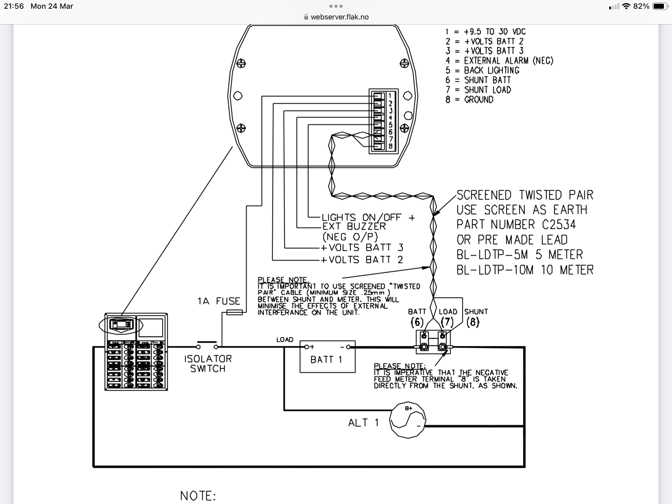
You might need to sketch out the wiring… Here is the manual for the BEP, do you have the 2 wires (7) and (8) connected directly to the load side of the BEP shunt as shown…?

-
If your device is just an inverter then you cannot also connect another ac mains source such as the travelpower. But if it is a combi inverter charger like ours, then you can. Assuming it is wired up correctly and supports power assist.
-
It's likely that the negative for the BEP is on the battery. Whereas to read correctly, the BEP negative needs to be on the bit between the 2 shunts. Probably at the moment the BEP is seeing the voltage dropped in both shunts, hence over-reading.
-
Ours is a bit like that, although recently it seems to be better for some reason. But we just turn it on powered by the inverter, and as soon as it starts we can switch over to Travelpower. Or these days, a combination of Travelpower and Combi Inverter. That is with a Zanussi ZW1300.
-
It is a bit of an issue. If you have a Combi you can limit the power demand from the Travelpower with the remainder being supplied by alternator/ batteries. If you know how! Worth bearing in mind that a washing machine only uses a lot of power whilst heating the water during the first 15-20 mins of the wash (depending on which temperature wash you select and how hot the incoming water is). So using a cooler wash, adding a kettle of hot water during the first fill or even plumbing the washing machine into hot and cold water via a selector, are all ways of reducing the problem time. Once the washer’s heater is no longer on, the power consumption is low so no problem being at idle.
-
It might well be the batteries, but first I’d check for a poor connection between the batteries and the inverter. Put a multimeter on the actual battery terminal posts and check that there is actually only 10v or so on the batteries when the inverter is switched on. If the batteries are at a significantly higher voltage then you have a bad connection somewhere, or maybe a faulty battery master switch. If the batteries are at 10v then yes you need new ones.
-
What size battery interconnects?
nicknorman replied to blackrose's topic in Boat Building & Maintenance
Yes. And as mentioned earlier, battery interconnect cables don’t take the full current. Half the current with 2 batteries in parallel. -
You can get ring terminals of various thickness (internal vs external diameter of ring) but since you now have them and presumably crimped on, could you not just snip a bit of the ring back so it fits?
-
Out at sea? If you are planning any seagoing trips, I wouldn't be climbing on the roof! But if you mean when out on the canal/river, normally there is some sort of thing to hold onto along the top edge of the roof, even if it just an upstand. It's a little bit difficult to see from your photo, but it does look like there is an upstand. It also looks like the gunnels are rather narrow - your boat is designed to maximise inside space at the expense of external usability perhaps. For climbing onto the roof you might consider folding step things, they allow 1 foot to be placed on them to get up onto the roof, and they fold to avoid catching them on locks / bridges. https://marinestore.co.uk/narrowboat-sprung-toe-step-chrome-n-70001-j160224.html?gad_source=1&gclid=EAIaIQobChMIuq3VwYWPjAMVtJJQBh270wGPEAQYASABEgLEIfD_BwE
-
It is wired correctly. As said, if the starter battery negative is connected directly to the domestic battery negative, and bearing in mind on most boats the alternator negatives are connected at the engine, then you effectively have 2 negative paths for the domestic alternator current, one via the shunt and the other bypassing the shunt going direct to the domestic battery negative via the starter battery negative. Net result being that only about half of the charge is registered by the shunt, but all the discharge, so the indicated SoC decreases to close to zero even if the batteries are fully charged.