


stuart
-
Posts
2,329 -
Joined
-
Last visited
Content Type
Profiles
Forums
Events
Gallery
Blogs
Store
Everything posted by stuart
-
From the album: VDO Tach display replacement
-
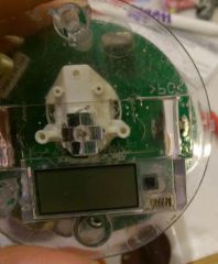
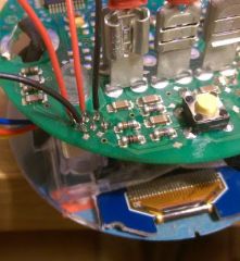
You will need to attach 4 wires to the old LCD header on the gauge's circuit board. There are 6 connections, in a staggered pattern. I didn't have many spare coloured wire available so had to use red/black - if you have 4 colours use them instead to help. A B C D E F A=SDA (data) red wire B=+5v red wire C=ground black D=SCL (clock) black wire E=not connected F=not connected The A and D connections go to the Arduino A4 (data) and A5 (clock) connections. The B and C connections go to +5v and 0v on the Arduino.Once these connections are made, you should be able to power the Arduino circuit up (using USB cable to your computer) and fingers crossed, the display will light up, and then display the hours counter!Hopefully everything works, if so you now need to reassemble the display in the reverse order as these instructions.You also need to push/manipulate all the new parts into the case and re-assemble it. Double sided sticky tape may help to keep things in place.Try and align the screen so that its straight when installed - I used the black stencil (0-4000rpm) so align the display and also to stick it in place. Final unit working...
- 79 replies
-
- 1
-

-
- Hour Counter
- Isuzu
- (and 1 more)
-
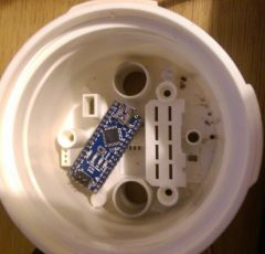
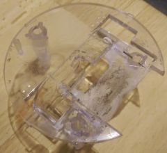
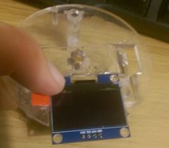
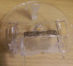
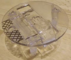
Dismantling the VDO gauge Remove the gauge from your boats engine panel and remove the connector from the back (this is a tight fit and may need to be levered out) On a clean workbench (where you are not going to lose the screws!) remove the 3 T10 torx screws from the back of the unit. The front panel may come away at this point, if not, push firmly on the metal connectors where the plug attached to, the front should now push out. Safely remove the clear plastic “glass” from the unit and keep the rubber seals. (did you know the gauge was double glazed?) Remove the black trim ring from around the display. Carefully using thumb and forefinger, prise the dial needle from the centre of the display - this will be very stiff to move, but break it and you will be buying a new unit so be careful! Now you should have a clear plastic assembly (with the black 0-4000rpm label on it) attached to a green circuit board. Carefully lift up the black label and remove it - its well stuck down! Place this face down somewhere safe you will need this to remain "sticky" You should now see the old LCD panel and a small ribbon cable running to the circuit board. Carefully remove the LCD ribbon cable from the circuit board by lifting the tiny retaining clip and pulling out the ribbon cable. On the bottom of the circuit board, you can see 3 legs from the clear plastic assembly - if you pinch each of these legs together the plastic should come away from the circuit board. You should now have a circuit board and a seperate clear plastic assembly, with an LCD panel and ribbon cable attached. Using brute force, remove the LCD panel from the plastic (lever it up) becareful not to crack the screen. We are going to put the new LCD panel into the gap where the original was. The new LCD is much larger, so you will need to cut out the marked area as per the picture. Note that the connections for the LCD are going at the top - the picture above shows the LCD upside down! Once the plastic has been removed (I used a Dremel type tool), the remaining plastic will need to be flattened down to make the whole area the same height so the LCD panel fits flush. The image shows the black marked area which needs to be reduced. You will also need to make a hole for the cables to drop through. Its really a job of trial and error to get everything nice and flat and smooth/aligned. Once you are happy that the LCD panel will fit snugly in the gap, you are most likely going to need to file down the bottom corners LCD panel's circuit board - just be sure there are no circuit tracks underneath! The picture below shows the LCD panel in its final position temporarly re-assembled. The Arduino board will just about fit into the spare space inside the back of the case - theres not much room. You may also be able to leave the USB cable connected and push this out the back of the case through one of the spare holes. This is useful if you want to later change the program and for testing.
-
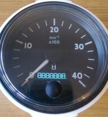
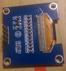
Programming the Arduino Start by programming the Arduino (ATMEGA328) using the Arduino software - http://arduino.cc/ there are hundreds of websites devoted to this topic so I won’t repeat them here. The source code is available from me, send me a message on the forum with your email address and I’ll sent it to you. Next, you will need to connect the display to the Arduino. To make the display fit inside the case, I had to remove the presoldered header pins and replace them with 4 wires. Make sure you leave these wires long enough to give yourself working room 15-20cm long is great. Also use thin stranded flexible wire so you can bend and twist it as needed. The display has 4 connections - VCC GND SCL SDA Connect the SCL (clock) to the Arduino pin marked D7 Connect the SDA (data) to the Arduino pin marked D6 Connect the VCC (+5v) to the Arduino pin marked VIN Connect the GND (ground 0v) to the Arduino pin marked 0V If you now power up the Arduino (using USB cable supplied) the display should clear, a "VDO" logo will be shown followed by "88888888" - if you have got this far, everything is working as expected.
-
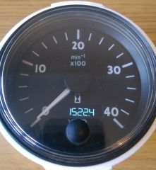
As promised, heres a description of how to repair the hour counter on a VDO tachometer gauge (also used on Volvo Penta) My tachometer is marked with the following model numbers, so this guide may work on other models of similar vintage (2004). My tach is a 0-4000rpm, with digital hour counter and inductive pickup from alternator. * KI "W", Induktiv * N02 012 165 (168) * Date: KW 36/04 Catalogue http://www.em-schiffselektronik.de/html/508475_Marine_Katalog_2004_2005.pdf Useful instructions on how to calibrate the gauge (once its working!) http://www.ybw.com/forums/showthread.php?263571-VDO-tachos-How-to-callibrate-and-make-them-work Lets begin with the background... These gauges have a tendency (fault!) to intermittently display the hour counter, eventually the display is permanently blank. The fault is due to a ribbon cable attached to the LCD display using a process known as chip on glass - practically impossible to repair without specialist tools/knowledge. Repair/replacement LCD screen Unfortunately, VDO’s original display (LPH3930-2) is custom made for them, and can’t be purchased, so rather than trying to repair the original LCD display, I’ve chosen to replace it with a modern alternative. The next problem is that modern displays “talk” differently, so an adapter is needed to convert the old signals into new. I spent many hours decoding the old signals and determining what they mean, the result is the knowledge to be able to build an adapter and understand the original LCD protocols. For those that are interested, the original LCD appears to use a chip similar to PCF8562 (http://www.nxp.com/documents/data_sheet/PCF8562.pdf) So, this project uses a tiny computer (AtMega328) and an organic LED screen. These parts are readily available for home hobbyist use. The actual parts I brought and used for this project were… White 0.96" I2C IIC Serial 128X64 OLED LCD LED Display Module For Arduino http://www.ebay.co.uk/itm/white-0-96-I2C-IIC-Serial-128X64-OLED-LCD-LED-Display-Module-For-Arduino-/261433793901 Compatible Nano V3.0 - ATmega328 Mini USB Controller Board + Cable For Arduino http://www.ebay.co.uk/itm/Compatible-Nano-V3-0-ATmega328-Mini-USB-Controller-Board-Cable-For-Arduino-/191257218511?pt=UK_BOI_Electrical_Components_Supplies_ET&hash=item2c87d18dcf Other websites/sources can provide similar products, just ensure the display is the same - and uses the I2C communications protocol - not SPI. On to the build...
-
From the album: VDO Tach display replacement
-
From the album: VDO Tach display replacement
-
From the album: VDO Tach display replacement
-
From the album: VDO Tach display replacement
-
From the album: VDO Tach display replacement
-
From the album: VDO Tach display replacement
-
From the album: VDO Tach display replacement
-
From the album: VDO Tach display replacement
-
From the album: VDO Tach display replacement
sh1106 oled 128x64 pixel 0.96 inches -
From the album: VDO Tach display replacement
-
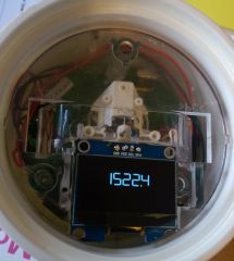
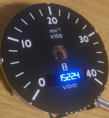
Heres a quick photo showing my prototype replacement display in action The actual display is a flat matt white/black display, although the camera makes it appear brighter than it actually is.
-
X8aGPbk5F4oxkw5E3ju8XeaPbIQmVE6JVn3Xrz3qKz54=w826 h889 No
stuart posted a gallery image in Member's Gallery
From the album: VDO Tach display replacement
-
So far, the only two parts you need are: A new LCD screen - I'm using an OLED one http://www.ebay.co.uk/itm/white-0-96-I2C-IIC-Serial-128X64-OLED-LCD-LED-Display-Module-For-Arduino-/261433793901 and an Arduino Nano http://www.ebay.co.uk/itm/Compatible-Nano-V3-0-ATmega328-Mini-USB-Controller-Board-Cable-For-Arduino-/191257218511?pt=UK_BOI_Electrical_Components_Supplies_ET&hash=item2c87d18dcf Total cost, about £9. You will need a soldering iron, and most likely something to cut some of the plastic, a dremmel would be useful.
-
I'd recommend any non-cast iron stove, I've got a Morso and the associated high repair costs when (not if!) a casting shatters or cracks.
-
I've got it all working now, just need to sort out cutting down a circuit board to fit inside the existing tach casing. Total cost to fix about £10 - and a lot of spare time!!
-
I've done exactly what you describe and it works fine, used a timer with relay to run the pump for 30 seconds after you switch the water off. I did have to fit the flow switch on the shower outlet though, it caused problems on the hot water inlet as I have a thermostat mixer which stopped the flow every now and then
-
If you've got a panel that only works when hot then you can try the hairdryer fix! Take the unit apart and blast the LCD/connector with heat from a hairdryer and then try to smooth the connector ribbon cable flat against the glass. Mine was completely knackered - no display what so ever!
-
Its taken me ages to workout how the LCD is used by these devices, but I'm happy that I've got it working! There are a couple of articles on the internet where people have cut out and replaced the hour counter LCD with a brand new hour counter - but you then lose the original number and also can't get to the configuration menu on the display (bet most people don't even know that exists!) My plan is to remove the existing LCD + bin it, then try and find something thats going to fit into the space left. I've written a tiny program to run and drive a new LCD screen (or similar) which can then be glued inside the existing case. I'm not spending a couple of hundred quid on a new VDO unit !!
-
Hello, its been a very long time since I posted anything on the forum, however, if like me you have an Isuzu engine where the hour counter built into the tachometer gauge (which is made by a company called Siemens VDO) - and the display has gone blank then I've got a fix! These tachometers are rebadged alot, and seem to be similar on Vetus, Volvo Penta and several other brands. Inside the hour counter it will be counting perfectly well, its just the LCD display thats gone. It uses a process known as "COG" - chip on glass, and then a tiny ribbon cable to connect to it - its the ribbon cable on the glass that breaks over time. I've managed to reverse engineer the LCD signals, so I can get a display working again, its not quite finished yet but wondered if anyone else would be interested in it?
- 79 replies
-
- 2
-
-
- Hour Counter
- Isuzu
- (and 1 more)
-
Yes Vactan can be sprayed when mixed with a little water - think it needs a high pressure sprayer though.