


stuart
-
Posts
2,329 -
Joined
-
Last visited
Content Type
Profiles
Forums
Events
Gallery
Blogs
Store
Posts posted by stuart
-
-
On second thoughts,
https://www.whiteline.com.au/product_detail4.php?part_number=W31487
TOYOTA LAND CRUISER 1981-1991 - LAND CRUISER 60 SERIES HJ
TOYOTA LAND CRUISER 1980-1990 - LAND CRUISER 60 SERIES FJ
TOYOTA LAND CRUISER 1985-2000 - LAND CRUISER 70 SERIESAppears to be a good match.
Bush
TypeBush
QtyOD
AID
BL
CFL
DFLOD
EC/Tube
QTYC/Tube
SizeSimilar
Bushing Size7 4 37.5 mm 9.5 mm 16 mm 2.5 mm 14 mm click here -
Looks like the mini part is too small, the outside diameter at 32.8m is smaller than the washers on the Pythondrive @ 34mm. The "top hat" is also 18mm vs 14mm.
I might give it a go anyway and see what happens!
These are the dimensions I got from this site https://www.whiteline.com.au/product_detail4.php?part_number=W81156&sq=280666

-
For anyone who's shopping online to find heater hose, I found https://www.autosiliconehoses.com/rubber-hose-radiator-heater-epdm-automotive-hoses-black.html
to be the most competitive priced, and free delivery if you spend over £40.
-
I'd agree @Alan de Enfield but I'd struggle to find hose that is 34mm I/D, you have to go with the standard sizes. There is a single barb on the inlets rather than smooth tube though, so if I can get the clamp around that, should be good.
-
 1
1
-
-
I took the plunge and pulled the pipes off to measure as I couldn't find any information online.
Here's the results, in case it helps somebody else.
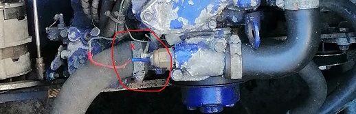
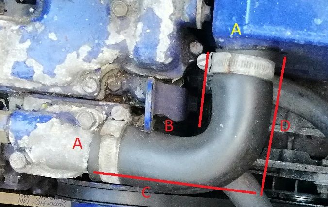
On the bottom of the header tank, is a 35mm outlet, requiring 35mm I/D hose
The other side of the pump is also a 35mm I/D hose (marked X below)
On the thermostat to header tank connection, it's a 90 degree bend.
A = 32mm outlet, requiring 32mm I/D hose
B = 72mm
C = 112mm
D = 100mm
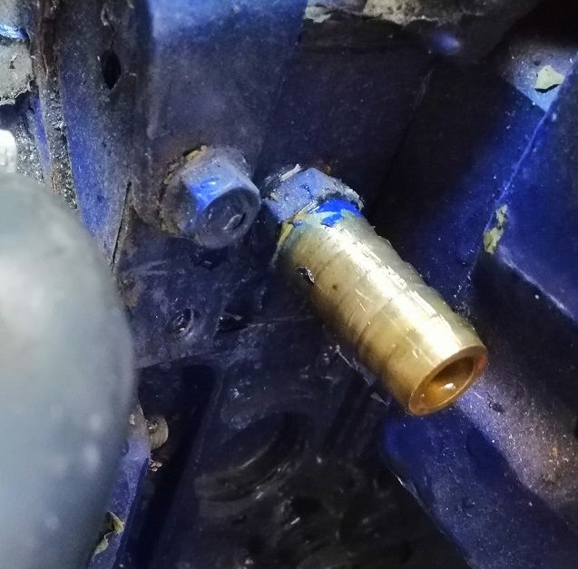
The hot water take off for the calorifier is two 16mm barbed fittings. Requires 16mm I/D hose.
-
2
-
-
Thanks Tony, I'll see if I can find the dimensions for those, the 'top hat' looks a little wider in the photos I've found.
May see if my local motor factors has some to look at.
-
Thanks Tony.
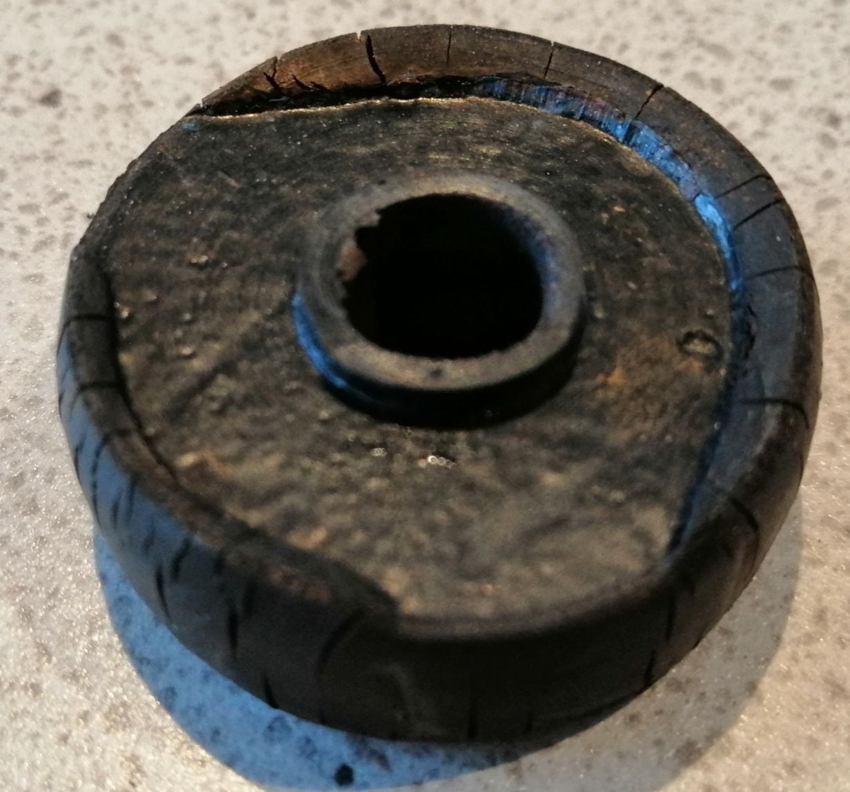
I've just been to the boat to remove them.
They have a 10mm hole for the bolt, the bushing is now 39.6mm in diameter (after being squashed) and 13 to 14.7mm thickness.
There is a little top hat that fits into the python unit, only a few mm tall and 14mm in diameter.
The metal washer that pushes against this is 33.7mm diameter.
As expected hard as nails after all these years
-
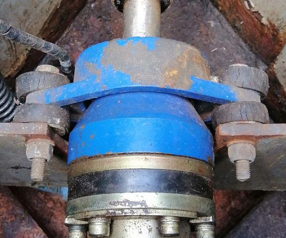
Opening a REALLY old thread here, but I've still not replaced the bushings - 6 years later they are still grazed, but working, although the boats hardly done any miles in that time.
I'm going to take a look this afternoon to measure up for after market parts.
My boats been left unloved for a number of years, so ignore the rust!
-
Hello everyone, Its been a very long time since I last posted, but I'm hoping you can help.
I've an Isuzu 35hp engine, model 4LB1 - which I've had for 15+ years now.
It's still using the original EPDM rubber hoses between the engine and skin tank for cooling, I'd like to swap those out to avoid failure due to the hoses getting brittle.
I've checked all over the existing hoses for the dimensions and found nothing - does anyone know what the internal diameter of the Isuzu water outlet/inlets are?
I've read through the service manuals, and whilst it tells you all the relevant info on disassembly - it makes no mention of the diameters!
I'm trying to get all the parts I need before getting to the boat, so as not to drag this out over several weekends, obviously I could just pull the existing pipe and measure, but that would dump all the coolant into the bilge, which I don't want to do (yet).
-
On 14/11/2020 at 13:56, nicknorman said:
1) turn on the MOSFET, 2) wait 75 mS, 3) turn off the MOSFET. Easy Peasy!
I implemented that logic in my diybms as well.
-
6 hours ago, MoominPapa said:
outputs get configured in error for normal relays
@MoominPapa just for information, I've implemented the DIYBMS v4 code tonight to provide a pulsed output on the relays should it be required. The relay switches on for about 100ms - anything less and the relay can't switch fast enough so nothing happens.
-
2
-
-
49 minutes ago, nicknorman said:
JLCPCB seems better for shipping.
I've used PCBWAY and JLCPCB, no problems with either.
-
3 minutes ago, nicknorman said:
However I have done lots of SM soldering and not yet had a problem. I use solder paste (PbSn, obvs!) and reflow heat it (using a temperature controlled heat gun). And a big magnifying glass! Provided the solder paste is in date it works really well.
You'll like my youtube video of reflowing using a frying pan then !!
-
2 hours ago, nicknorman said:
AD7280A
It will be fun soldering that by hand!
Are you going to get those machine assembled ?
8 minutes ago, MoominPapa said:I'm a bit of a dinosaur, and prefer a text editor and makefiles to an IDE
Thats the nice part of PlatformIO - you get to keep the Arduino 3rd party libraries but in a much more friendly way.
-
1
-
-
10 minutes ago, nicknorman said:
i know a lot of people use Arduino but I find the development environment very poor. Starting with the stupid name “sketch”!
I agree, thats why I don't use it - take a look at platformio or the Visual Studio Code solutions, much better developing and debugging platform.
Are you building the alternator regulator yourself ?
-
Should be easy enough to change my relay code to provide a pulse relay output instead of latching.
At the moment I'm not reading current, but the system is designed to allow this - I was looking to use the ACS758 (hall current sensor - up to 200A).
Although I could also design a seperate module specifically for this purpose if needed.
-
3 hours ago, nicknorman said:
Not to mention everthing being on a web interface! I'm not a Millenial!
I'm sure I can russle up a green screen terminal for it ?
The BMS was designed for large battery banks - take a look at DIY Powerwalls - there are people with 100kWh+ of battery capacity powering their off grid homes for weeks at a time.
The trouble with most chinese BMS type systems and ebay specials is the balancing current is tiny - 50mA or less in most cases and would take forever to balance a large pack.
-
32 minutes ago, MoominPapa said:
If not already possible, and option to drive bistable relays of the Tyco BDS-A type would be useful. These need two coil circuits, one to open the relay and one to close it, with 10-15 mS pulses.
At present the BMS drives 4 seperate relays (it could go up to 8 ) and you can configure what each relay is for based on need.
I don't do anything clever with the timing at the moment, but thats easy enough to do with a microcontroller.
Assume for these bistable relays, a "disconnect" rule would just connect the relevant driving relay for 15mS and then disconnect.
-
Hi @Dr Bob my BMS was designed originally for people recycling laptop 18650 cells but it works okay with LiPo and LifePO4 cells as well - aka DIY Powerwalls.
The DIY BMS has a simple moduler design, temperature monitoring, along with generic relay outputs which are controlled by software defined rules.
So it would be quite trivial to have rules designed to switch relays off at certain voltage set points or raise alarms when cells are above/below set voltages or temperatures.
The cost is also low, each cell module is about £5 and the controller about the same. The code may need a bit of tweaking for use on a boat, but nothing that can't be easily solved.
Let me know if you'd like to have a chat about it, or even a demo unit or two. I'm in the Midlands.
-
I've not been on the forum for years, but noticed the article in Canal Boat magazine this month on Lithium battery systems and LifePO4.
If you are looking for a DIY BMS - I've built/designed one thats proving to be quite popular.
There is another forum where the discussion takes place.
https://community.openenergymonitor.org/t/diybms-v4/11292
-
Hi John, no reason the display can't be separate - although you will need to disconnect the original - the replacement Arduino emulates the display so both together will get confused.
The connection to the hour counter is over an i2c connection, so you do need to keep the cables as as short as possible, possibly with shielded cable as well.
-
Sorry, just get a 404 error on the link provided!
-
Its been ages since I last posted, however looking for options to replace my existing dry exhaust for something a little quieter.
Its an Isuzu 35 engine, with a dry exhaust - about 4.5" by 15" both ends have a 1.5" male thread (screw on) fitted with a flexible pipe to engine.
Another quick question - the flexible pipe to the engine from exhaust is really flexible - is this normal? Its not leaking!
Thanks
-
Fascinating thread.
A couple of quick questions:-
1:- it looks like the Arduino Nano can be obtained with header pins pre-soldered or without. Which does this project require?
2:- what power soldering iron should be used in this project? I'd rather not fry either the OLED or the Nano if I can avoid it!
Thanks in advance.
It doesn't really matter on either point, I use a 25W iron - as long as its not a 100W beast you will be fine.
It may be easier to fit the Nano into the case of the gauge without the pre-soldered pins on it - although you will have to connect a few wires instead manually (soldered on).
You could also try a "micro" board
Although more expensive than the ebay clones.


Python Drive - replacement parts
in Boat Building & Maintenance
Posted
Thanks Tony. The original parts quote "P30-R: silent rubber blocks should be compressed to 13 mm."