Mikexx
-
Posts
541 -
Joined
-
Last visited
Content Type
Profiles
Forums
Events
Gallery
Blogs
Store
Everything posted by Mikexx
-
I have been successful in measure with a wire or similar going round the pulleys. Its then a question of finding a size that closely matches. By way of your example your 4PK1052 will be 4 ribs and a length of 1052mm.
-
My go-to in these situations is to use threadlock. It stops bolts coming loose as well as keeping them captive.
-
Most people advocate phosphate free if you're going to discharge directly into the canal. I'm sure any detergent conforming to that will have on the package "low phosphate" or "phosphate free". Their Almat range is quite extensive, so can't tell at a glance the issue. I guess all detergents aren't good for the environment but perhaps some are better than others?
-
I have an engine that hasn't been run for years. It's fairly clean but has been subject to lots of "training use" and so things may not be quite as they seem. Since the sump had to be replaced I checked the bearings and came to the conclusion they looked serviceable, so put everything back. Just as well I looked as the mains were loose as well as other things like the oil pump bolts. In order to release the rear-most bearing I took the rear plate off. There wasn't a seal, just a flinger like disk coming out of the crank that looked as if it ran in a groove by the end plate. I recall that some use this method of retaining oil, but on looking up on the subject some had proper oil seals and have heard felt pads mentioned? Without taking everything apart again, is there a way of knowing what type of 'seal' I should have at the rear?
-
From what I remember the area of pulley with the holes mentioned are recessed such I'm not sure that tool will work? Do let us know how you get on with it as it saves a lot of faff removing the starter.
-
I confess I have been wary of using a rattle gun where there is a chain involved. When I have removed and replaced a crank-bolt I have always taken out the starter. The ring gear should be pretty strong. It has to put up with the hammering action of the starter pinion. While there are two small bolt holes on the pulley, you would have to make up a tool to bolt to the pulley or your studs or screws would simply bend after supplying the sufficient torque to undo the crank-bolt.
-
A 2008 Transit with a 2.4 Duratorq engine didn't have a lift pump. It could be an utter pig to start. No sign of any air ingress and even changed the filter body and other fittings. As a partial solution I fitted a Facet fuel pump that only ran when cranking!
-
It's not a term anyone else would generally use in the circumstances you now describe. Rocking valves occur when the exhaust valve is closing and the inlet opening. There will generally be some overlap, such the valves will be slightly depressed. Can we rotate the crankshaft one turn, so the camshaft is on the money? There is a direct 2:1 relationship between the sprockets. If everything else is working, it is either fuel, or perhaps poor compression. It might be worth looking at the procedure to prime the fuel system.
-
That is precisely my presumption. Confusion clouds any problem here. The definition of valves "rocking" is another ambiguity; all the more likely from a novice.
-
Do you agree that valves on 4 will be rocking when the crank is TDC for both 1 and 4? Simply rotating the crank 1 whole revolution will now make valves on no 1 rock. It also depends on your definition of "rocking". A firing cylinder will have both valves at clearance. On the alternative stroke the swap from exhaust to inlet often overlap such they are tight. My definition of "rocking" is where you can see the change-over from exhaust to inlet. The OP might have a different definition, where the tappets have clearance on the firing cylinder.
-
I missed that bit. That confirms that all is well. All the OP needs to do is rotate the crankshaft one whole revolution and hey presto, the marks will line up, and both no 4 and no 1 will be at TDC and the camshaft will be 0 degrees out. What am I missing here? How does he know which is the firing stroke from an injection POV? I suppose if he slackens the HP injection unions he might be able to film the valves and "pumps" together on cranking. Then examine the video frame by frame?
-
Sorry, but the cam 180 degrees in error would make do difference. One rotation of the crank would make it right again. I'm wondering if the OP means the crank is 180 degrees out, so 90 degrees at the camshaft? That would never run. In fact I would wager valves would have crashed into pistons.
-
A seized engine from loss of oil after a couple of months will not run smoothly. The marina's responsibility when they haul the boat out Advisable for bondage. Difficult to use these shackles all by yourself, some form of mutual co-operation might be required. Nothing some tissues won't resolve.
-
Any ledge would be made of weld and ground accordingly. My thoughts is that I can make full use of the hole at the bottom of the top hat so it should be pretty strong and homogenous. If anything breaks then it's head off. Something I had expected prior to discovering the top hat was a separate item could be removed. At the moment I'm happy to let sleeping dogs lie, this has been a useful learning experience.
-
I will bear that in mind. I had previously assumed they were machined directly into the head. I was also thinking about Tony's idea. I have access to materials and could weld a ledge on a steel rod with a slide hammer. Given the boat and workshop are a modest distance apart and also a short walk I would prefer to go prepared.
-
I felt I did the best I could without knowing the Top Hats were removable. I have now read that they can stick to the injector and come out as one lump. Mine didn't move. It is possible this was a bodge by someone who had the copper washers but not the top hat, or they couldn't remove the top hat. I tested the new injectors for opening pressure and pattern. I felt the spray pattern was lopsided towards the side Aux hole and was a good mist. I didn't check for back leakage and TBH assumed that would be the least of my concerns especially with new nozzles.
-
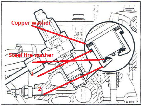
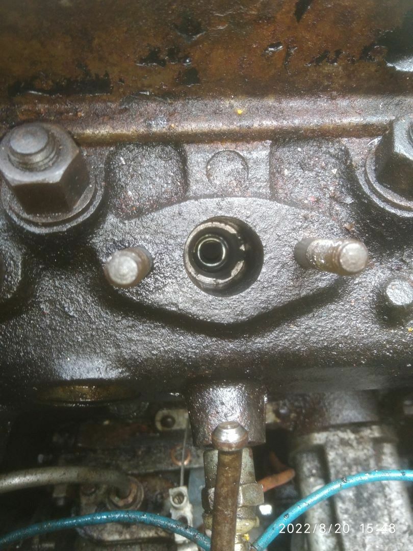
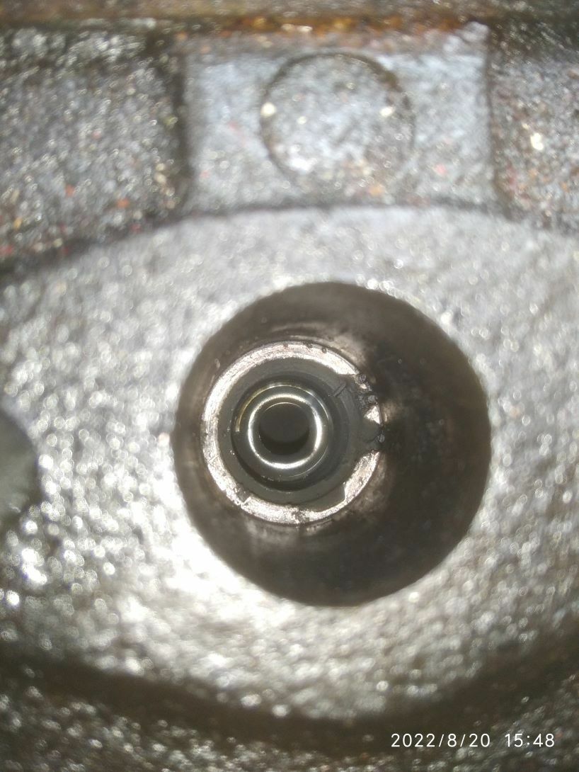
I changed the Steel fire washer and the top copper washer. Yes, the fire washer was at the bottom of the bore, this would have been changed, or was the changed item. I assume you mean Thin Washer [1] Top Hat [2]? I wasn't aware that the 'top hat' was removable, and it seems it is this item that has become eroded. For future reference, are they easy to change? The ones advertise on ASAP Spares are a copper colour. The ones at the bottom of my injector bores are very steel coloured.

-
Yes, I got a modest supply of heat shield washers from Bob Becks and wouldn't reuse them.
-
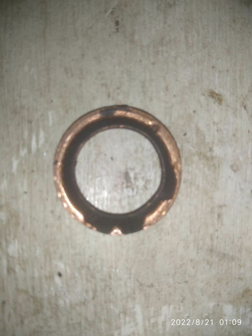
My engine has always smoked and would miss on tickover, firing on 3 then back on 4, so took the plunge of sorting out some spare injectors. In the end I got 4 new nozzles and use my pop tested to set the opening pressure. I got new heat shields and new copper washers hoping this would be a simple job. After removing the old injectors I was aware that not all the old copper washers were the same, two were stuck in the injector bore and a bigger diameter than the others. I was also aware that No 2 injector bore looked as if suffered erosion. After fitting the refurbed injector with a new washer, it was obvious when cranking the engine that this washer wasn't sealing. After running for just a minute or so this is what this washer looked like: Given the old injector didn't leak the clue was in the old washers. The standard washers are OD: 21.0mm / ID: 14.5mm / Thickness 1.5mm The old larger diameter washers were OD: 21.6mm / ID:17.0mm / Thickness 0.85mm To compare with the bore, this is ~21.5mm, the injector body mid diameter being 21.3mm So, I heated the old 21.6mm OD washers to red heat and quenched them in water to anneal them. I fitted these into the No 2 Injector bore and after refitting and starting the engine there were no leaks. I can only assume that when tightened down the washer expanded sufficiently sideways to seal against the bore if not just the 'shelf'. It was a relief that I didn't have to swap heads. I did come across this size washer on a US website namely: https://www.superiorwasher.com/washer/815-422-040/815-422-040.html but I can't find any UK suppliers. I found a seller on eBay selling a washer with the same OD 21.6mm but with a ID of 8mm. I'm sure the centre ID could be enlarged. I'm pleased to say there is less smoke, and there is no misfire. I had a look at the old injectors. 2 were marginal in that the opened at a slightly lower pressure and spray pattern was distorted. The other two were worse, one would open at half the pressure to get a dribble out of of the idle spray hole. There being no 'snap/pop' action I might expect from a half decent injector. The injector nozzles worked out at a little over £50, and the tester another £60. Apart from setting opening pressures the tester gives you some confidence an injector is in working order before fitting. I thought I would pass on my experience. Also don't allow any exhaust to leak by the injector for any length of time!
-
In the end I used 4 cable ties to bring the dipstick max line line up with the oil level. After various stories here I am just as worried with the oil level going up as well as going down!
-
Thanks for the heads up. I now feel a fool, especially as the bearing at the low end of it's rotation shows con-rod bolts! At least my question, and your answer, will save anyone else's blushes!
-
I'm not sure if that is to scale. If I put the image into MS Paint, and after some measuring in pixels, at BDC I put the lower bolt on the crank to be on the sump bottom. BICBW
-
I take your point. I recall a friend travelling some distance, got to mine and checked the oil level. It was below the end of the stick. He poured in a litre, and it was still not on the stick. His thinking was, if he got there ok, he could surely get back home. When I said 4.6/7 litres, I was going by eye on the side of the container! 🙂 I think I might go the route of adding cable ties to lift the dipstick off the bottom, and perhaps raise it the odd 20mm or so, so the max mark should match the known volume of oil.
-
There are anecdotal stories of dipsticks going through the sump, so wary of leaving the dipstick in this state. I can leave it midway by stiction, but feel that is a temporary state and prefer a permanent solution. Currently, after filling with ~4.6/7 litres the oil level was above the max mark with it touching the bottom, I think it's the probably on the "X".
-
The sump looks the original tin one, like yours. I've been looking at MGB dipsticks and there seem to be 3 types, though I'm pretty sure mine will be the latter type. With a push fit tube and straight dipstick. However I did read somewhere that BMC engines made in Turkey were different again.