IanD
-
Posts
16,003 -
Joined
-
Last visited
-
Days Won
117
Content Type
Profiles
Forums
Events
Gallery
Blogs
Store
Everything posted by IanD
-
All understood, but you're not allowing for the fact that the demographic of game-players and that of boaters is very different. There are lots of gameplayers out there, mostly young, and mostly not living on boats. There are lots of boaters out there, mostly older, and mostly not gameplayers. That's what the data shows. Still, there will be a few, and they only have Three as a truly-unlimited provider... 😉 P.S. Grandkids visiting occasionally for a few days don't count, heavy use day in day out is what racks up the data...
-
Those figures (chosen to keep overall revenue unchanged) are on top of the x2.5 (+150%) overall increase -- so compared to today x3.75 for new boats, x2.5 for typical boats, x1.25 for old boats... Don't forget the suggested 50% CC surcharge, so CCers would pay x5.6 for new boats, x3.75 for typical boats, x1.9 for old boats. Yes that a x4.5 difference between the cheapest license (HMer with old boat) and the most expensive one (CCer with new boat). That's what happens when you need to raise a lot more money and try and be nice to some people, some others have to pay a *lot* more... 😉
-
I've never downloaded a >100GB game in my life, and I suspect neither have most other boaters... 😉 Not disparaging people who do, everyone chooses how to amuse themselves, but I suspect you and Torblimey are a *very* small minority of boaters -- just like people with £300k hybrid boats are ... 😉
-
And each of those boaters gets a *massive* benefit from being on the canals, and everyone else gets a *tiny* one... Nobody -- apart from you -- is saying that boaters ought to pay the entire cost of running the canals or keeping them navigable, or that the license fee could go up 400%. What we're saying is that license fees are extremely cheap compared to anything else comparable, that CART need more money, and that boaters should pay more to help keep the canals navigable because this is preferable to the entire system carrying on deteriorating to the point of being almost unusable at times. Which you keep complaining about (all the stoppages) while simultaneously objecting to any significant license fee increase. Do you really not see the cause and effect here?
-
Except 1% of boaters paying extra has sod-all effect on CARTs finances, what's needed is 100% or boaters to pay more... 😉 (but see above post about how to make this less nasty for the likes of LadyG...) P.S. Beaten to it my @MtB. Isn't it astounding how many people simply don't seem to understand how finances and markets work? 😞
-
Of course this could be fixed by means-testing, CART charging a lower license fee to those on low incomes or the unwaged, and more to those who are much better off. I can't see there being any objection to that, or opportunities for fiddling the system... 😉 A much simpler approach -- far less admin effort, no privacy issues, and harder to fiddle -- would be to charge by boat age, say going from 1.5x for "new boats" through 1x for "typical age" boats (12yo?) to 0.5x for "old boats (25yo or above). Which would solve the problem for low-income people like LadyG and others who tend to have older cheaper boats, and get more money from people like me with new shiny boats -- who must have been relatively well-off to buy an expensive/new(-ish) boat in the first place. Couple that with area-based charging and a bigger CC surcharge (+50%?) to make up for the money CART don't get from CCers compared to HMers, and surely everyone would be happy, including LadyG? 😉
-
You're not by any stretch of the imagination a typical data user then -- Three is your only option... 😉
-
I'm not missing the point at all, I'm saying that even large percentage increases in the license fee (e.g. +150%) are not going to drive many boaters away because today it's a small part of their total annual costs. There would be howls of protest especially from the NBTA and their supporters, but most boaters -- liveaboards and leisure -- will just suck it up. If you're a CC liveaboard with total annual costs maybe half compared to living on land, the cost would go up to two-thirds of living on land -- where else are you going to go? My point exactly -- I'd rather pay more (+30% total per year?) for a system that works than what I pay today for one that's falling apart and doesn't.
-
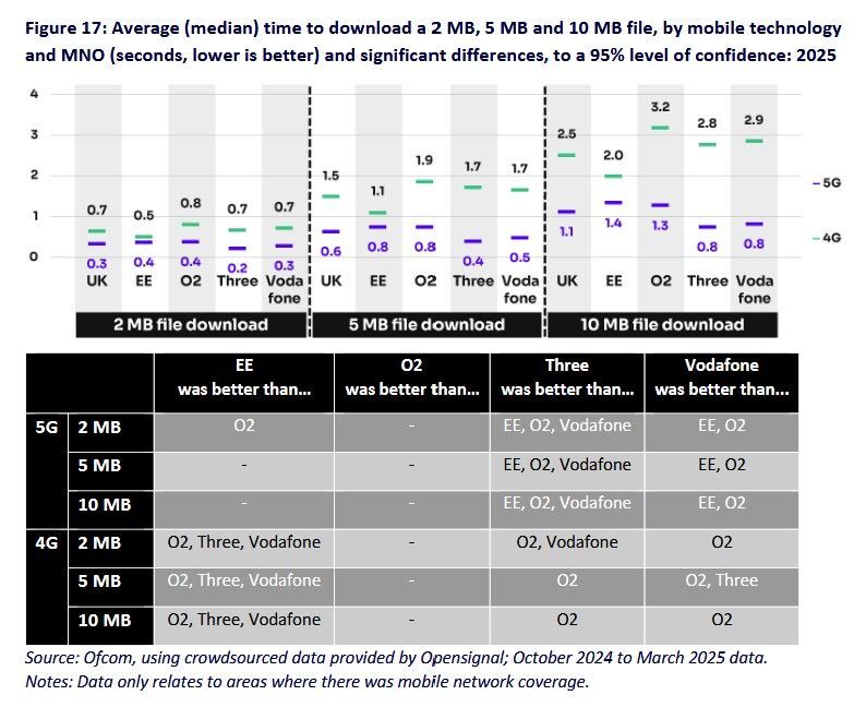
For anyone using terabytes per month Three is the only option, all the other networks "unlimited" packaged have FUPs (Fair Use Policies) of typically 600GB/month... Thought you have to do an *awful* lot of UHD streaming/online gaming to get beyond this... 😉
-
It wouldn't greatly reduce the number of leisure boats (80% are HMers?) who currently pay for a marina or online mooring (£3000pa typical?) since their total costs are similar to CCing liveaboards (or higher?), so will have similar sensitivity to total annual price rises (which is what the Laffer curve works on). Out of the 35000 boats on the inland waterways, I'd be amazed if the number dropped by as much as 20% if the license fee went up 150% (~30% higher annual cost for many/most boaters, leisure or liveaboard) -- but that still means double the income for CART.
-
I don't think there's the slightest doubt about the "sweet spot", especially given the increasing number of boaters in the last 15 years or so who are living aboard because it's by far the cheapest way of living in any kind of comfort (I'm excluding rotting caravans parked up somewhere). Given that typical license fees today are around £1000pa and it's usually estimated that the total canal living cost including everything is around £5000pa *and it's this that determines whether people stay or leave*, I'd have thought that a doubling of the license fee wouldn't drive many people away -- after all it's a 20% increase in total living cost, not much more than a few years of inflation or what happens when things like Ukraine happen. An unpleasant shock but most people will complain and carry on as they are. A 400% rise (+£4k) would put annual living cost up to ~£9k (+80%), and this would undoubtedly drive a significant number off the canals -- but then CART would get 4x as much from those who remained. Still this is probably going too far, quite possibly past the peak of the Laffer curve. Taking all this into account, I'd guess that if CART want to maximise their income from boaters something like a 150% increase in the license fee (to ~£2500pa typical) might do this -- after all, this would still mean that boaters were typically only paying about a third of their total living costs (which would go up by ~30%) to CART in exchange for having all those now-properly-maintained canals to live and cruise on...
-
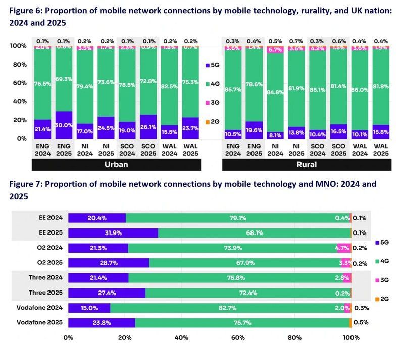
Latest 2025 report of networks across the UK: https://www.ispreview.co.uk/index.php/2025/07/ofcom-study-examines-uk-speed-and-coverage-of-4g-and-5g-mobile-networks.html https://www.ofcom.org.uk/siteassets/resources/documents/research-and-data/telecoms-research/mobile-matters/2025/mobile-matters-2025.pdf?v=400314 A few selected things relevant to boaters, confirming what has often been said: EE have the most connections made using 5G -- but in rural areas more than 80% of connections are 4G EE had the best 4G performance, Three had the best 5G performance, O2 was worst for both This may change in the future when the Vodafone/Three merger takes effect...

-
And some of that £51.5M comes from hire companies paying license fees to CART -- yes their customers then pay them to hire the boats, but they don't see license/mooring fees directly and anyway these are a tiny part of hire fees. Either way, ~35000 boaters pay a small fraction of CART income -- probably less than a quarter -- and get far bigger benefits for this than anyone else, even with stoppages. And as is repeatedly pointed out, what they pay to CART in license fees (and even mooring fees) is a lot less than anyone on land pays for a place to live, so it's difficult to avoid the conclusion that since CART don't have enough money boaters should pay more. That's still true regardless of the (often valid) objections of "I can't afford to pay more" or "it'll price people off the canals" -- just like on land, the answer to this is for society to find ways to support such people, not insist that CRT license underpricing continues leading to the system going to rack and ruin. Of course the alternative solution that would keep everyone happy is for the extra money to come from the taxpayer not boaters, since it's a drop in the ocean compared to other things the government spends (wastes?) money on -- but this doesn't seem likely to happen... 😞
-
This post cannot be displayed because it is in a forum which requires at least 10 posts to view.
-
This post cannot be displayed because it is in a forum which requires at least 10 posts to view.
-
This post cannot be displayed because it is in a forum which requires at least 10 posts to view.
-
The most reddest of red paints?
IanD replied to pedroinlondon's topic in Boat Building & Maintenance
Alfa red -- presumably after the car... 😉 https://shop.craftmasterpaints.co.uk/products/alfa-red -
They will -- and if CART put up mooring fees for their directly-owned moorings to make more money, you'd expect the marinas to put their fees up too, which means they make more money, which would give CART justification to raise the rent/lease fee when it comes round for review. And that will appear in the CART accounts as their income from property/investments going up... 😉 There's no other way CART can put this into their accounts, because they can see the lease/rent income from the company but they can't directly see where the company revenue comes from -- it could have come from mooring fees, or owning and renting boats out to ladies of negotiable virtue, or any other part of the business...
-
And I've now corrected it. If I went back and edited the original, I'm sure someone would accuse me of trying to hide that what I said was wrong -- which it turned out to be after more information was provided, as I said in a later post... 🙂 If a boater pays mooring fees to CART that counts as mooring fee income; if they pay more, CART get more. If a boater pays mooring fees to a business paying a lease fee to CART then the income from the business to CART counts as property/investment income; if the boater pays more, it all goes to the business, CART get nothing extra.
-
I agree, now more details have been provided -- see previous post... 🙂
-
That's your suspicion/opinion. Do you have any actual evidence? But even if you're correct, then yes it's money going out of your pocket, but it's not going to CART. The marina or boat club could double your mooring fee and CART wouldn't get an extra penny more -- or you could leave and pay nothing and CART wouldn't get a penny less. You're contributing to/paying a business which isn't CART. What CART see is a fixed income from leasing a property/business, which by definition is investment/property income. This has been explained several times now...
-
In that case they'll count as "mooring fees" not "investments".
-
So, which is it going to be then to fix the canals? 1. Taxpayers pay -- DEFRA doubles/trebles the grant 2. Boaters pay -- CART doubles/trebles license/mooring fees 3. The canals pay -- a good part of the system (500 miles?) closes down I would bet that only a small part of that "investment income" comes from boaters. And the point anyway is that it's not money going to CART, it's going to the investment company (e.g. Aquavista) -- if they make more or less money from moorings it has no effect on CARTs income. That's what happens when you sell off assets to make short-term money, they're not in your control any more, and you don't get any extra profit/income they make. Your (higher) mooring fee would be contributing to Aquavista profits (and their shareholders), not CART maintaining the canals properly... 😞 See marinas, water, telecomms, railways, electricity, gas, Post Office...
-
This post cannot be displayed because it is in a forum which requires at least 10 posts to view.
-
The most reddest of red paints?
IanD replied to pedroinlondon's topic in Boat Building & Maintenance
But that's not what RAL is for, even if you're colourblind (like my son) -- it's to ensure that what you see on the swatch matches what you get in the tin. However the light conditions really matter -- using the colour fan at home I chose RAL3001 Signal Red for the handrails etc. on my boat, and when I finally saw it on the boat in bright sunlight it was too orange-looking -- as was the colour fan when I looked at it under the same conditions. I ended up getting them repainted in RAL3003 Ruby Red which was much more the colour I was looking for...