


Eeyore
-
Posts
1,154 -
Joined
-
Last visited
Content Type
Profiles
Forums
Events
Gallery
Blogs
Store
Posts posted by Eeyore
-
-
17 hours ago, Michael Siggers said:
Good Afternoon
Hoping someone may be able to shed some light on a problem which has started today.
I had to move the boat this morning so that it could be taken out the water for blacking. All good so far.
The problem came to light when I had to turn the Engine off. On the Bukh, to turn the Engine off, the key has to be pushed in and turned to the 11 o'clock position, at which point the buzzer sounds, the engine stops. The key is then turned back to 12 o'clock and removed.
However, this morning, when I did this to stop the engine, the engine stopped but the Oil and Amp light came on and stay on, even when the key is turned back to 12 o'clock and removed. For the last week it has been fine as I've been crusing in it. It was fine yesterday when I arrived back, so not sure what has changed overnight. The lights do go out if I turn the Engine Ioslation off, but come back on when I turn the Engine Isolator back on, even with no key in.
The ONLY thing which I did this morning, by mistake, is that I unplugged the Shoreline from the boat first before the land connection. I had turned the Victron Inverter on before unplugging to maintain 240V.
I spoke with Nick at TW Marine and he has suggested that a short may have developed on the connections on the rear of the Key Switch which I will be looking at as soon as possible, but just wanted to see if anyone had any thoughts.
Just seems odd it was OK yesterday and now today, it's decided not to be.
Kind regards
Mike
Sounds like a Bosch switch? I just flooded mine with contact cleaner lub. Lots of muck and spiders can get in via the quite large gaps in the casing.
-
55 minutes ago, Tracy D'arth said:
I still think that you could find a nut to go inside..........................................
Keep trying, he’ll get there eventually😎
-
 1
1
-
-
Get a "T" handled hex key and a length of string as a wrist strap for the outside. Small hex keys are difficult to hold and often dropped.
You may occasionally encounter one of the more interesting things about working with stainless fasteners; their ability to lock up solid despite only being spun on by hand. Just have to shear or cut them off and try another one.
-
Have you bled all the radiators (and any other bleed points) before running the Webasto?
You will need to leave the charging loop connected and turned on whilst bleeding the system; and the main domestic water pump switched on.
-
 1
1
-
-
The blue arrow points to red knob for adjusting the pressure relief valve. These can sometimes stick/weep, so its worth checking that nothing is dripping from the pipe marked in red.

-
1
-
-
22 minutes ago, longy said:
Not 100% sure but doesn't the expansion tank take care of that.
In the operating manual for the boat under the central heating system it states
A connection is fitted to fill the water system which is located in the rear deck locker the operating pressure should be checked on a regular basis on the gauge on the expansion vessel and maintained at the correct level by topping up with water mixed with antifreeze.
Hope this helps
As an update I have managed to fill the expansion tank as there was a feed loop by the tank as Tracy suggested.
Now it appears that by running the system dry I might of damaged the webasto as there's white smoke coming from the exhaust and a smell of diesel.
It looks like a repair is on the cards
Thanks for the update. The forum software has an annoying habit of combining posts, and making it difficult to follow threads sometimes. I'm still curious as to why the header tank is there at all. Might as well remove it as its only taking up valuable space.
-
6 minutes ago, longy said:
Not 100% sure but doesn't the expansion tank take care of that.
In the operating manual for the boat under the central heating system it states
A connection is fitted to fill the water system which is located in the rear deck locker the operating pressure should be checked on a regular basis on the gauge on the expansion vessel and maintained at the correct level by topping up with water mixed with antifreeze.
Hope this helps
Not sure how repeating your self is helping us to help you.
At least give us the picture I reqested 😎
-
Humour me please.
You can get your hand all around the plastic "header" tank, and can't feel or see any pipe or hose connections?
I would consider it very optimistic to use gate valves to achieve 100% seal regardless of actual function. You need to trace where these are connected.
A new image of the gauge from slightly further back might be helpful.
-
Rather depends on whether you have a currently non functioning gauge on the panel, or intend to fit a stand alone gauge.
A photo of the panel would be helpful.
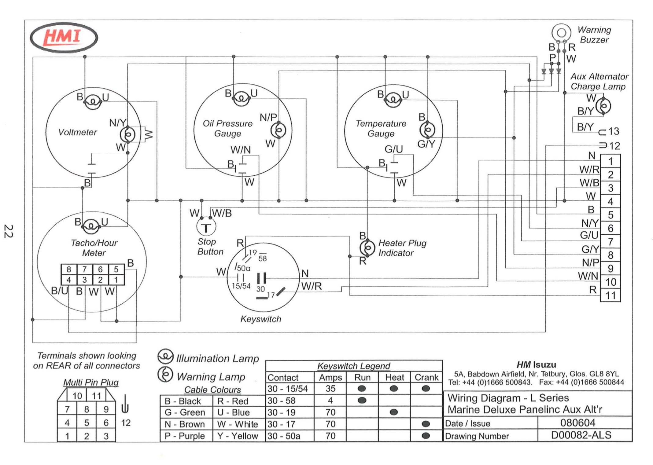
The green/blue wire is for a gauge. (Some manufacturers only produce one wiring loom, and will have all the optional wires installed regardless.)
Do you have the wiring diagrams?
-
2 hours ago, Alan de Enfield said:
Attached screen shot of LPWS spares manual, showing the starter solenoid and part numbers.

Wouldn't that be the grounding solenoid for the "insulated" return wiring harness?
-
Morse control stuck in neutral?
-
1
-
-
It's also worth checking the spill (return to tank) pipework for damage/restriction. Has been known to create similar symptoms.
The coolant pipe thing may be a red herring, there are a lot of incorrectly labeled images on the web.
-
I think the TNE engine has very small coolant hoses running to a temperature controlled advance unit. The later TNV certainly does. A blocked hose will leave the engine running in "cold start" position.
Can anyone confirm?
-
14 minutes ago, Doodlebug said:
I agree that running an engine for hot water and trickle charging is not suited but putting a 120a load on it to charge lithiums is going to be good load on the engine - which after all was built for generating power?
This could work - I will investigate how the engine is mounted because if I can bolt to the floor it would be ideal!
I wonder how I would tension the pulley though.
A sliding mount for the secondary shaft bracket will work with the existing (primary) belts.
A polyvee 6PK belt with a tensioner pulley running on the back of the belt will allow for a fixed relationship between the secondary drive pulley and alternator, and will provide additional wrap (belt contact) on the smaller alternator pulley.
-
2 minutes ago, Doodlebug said:
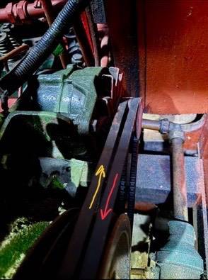
I believe the red arrow but does it make a difference?
it’s quite hectic behind. Here is another photo and pipe might need moving but that’s not impossible. Why what were you thinking?
pulleys on a pillow block might might work?
Yes, I think David Macks idea will fit below the alternator. The intermediate shaft mounted on two bearing (on a suitable bracket). Both pulleys at one end for a forward facing alternator, or one each end for an aft facing alternator. Depends which gives the clockwise rotation required by most modern integral fan alternators.
-
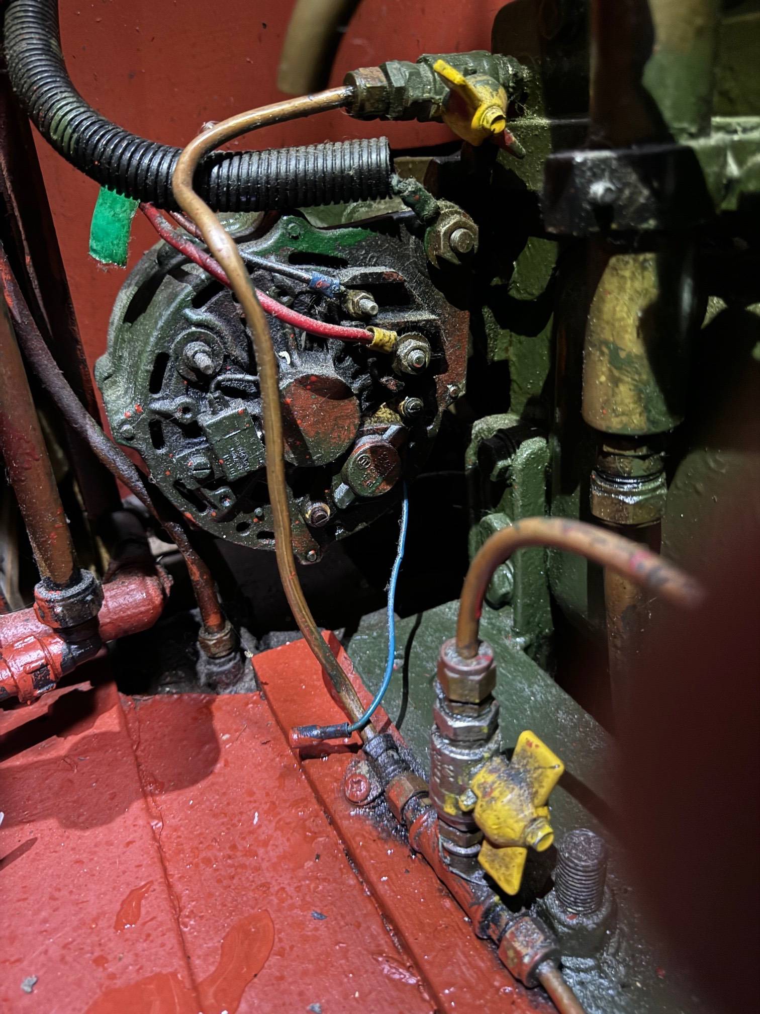
Is there much clearance at the back of the alternator?
What is the direction of rotation? red or yellow arrow?
Which 120amp alternator are you thinking of?
-
Picture of existing setup please.
-
8 minutes ago, MtB said:
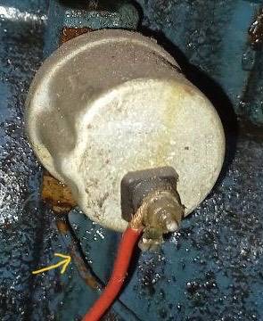
Looks more like a pressure switch for the warning light to me than a thermistor, which a temperature gauge sender will be.
Yes of course, I think I just got used to seeing all those tiny modern ones 😇
-
9 hours ago, nbbranwell said:
Hi all,
What is this part, and should I carry a spare?
Curious that it has a pipe (usually for a gauge) on a fitting behind the sender.
Probably worth following the pipe and wire to see where they end up. Might be an oil temperature gauge sender?
-
@BlueStringPudding Hi, any update on the coolant issue please? or still the same?
By the way did you check under the floor at the back of the boat?
-
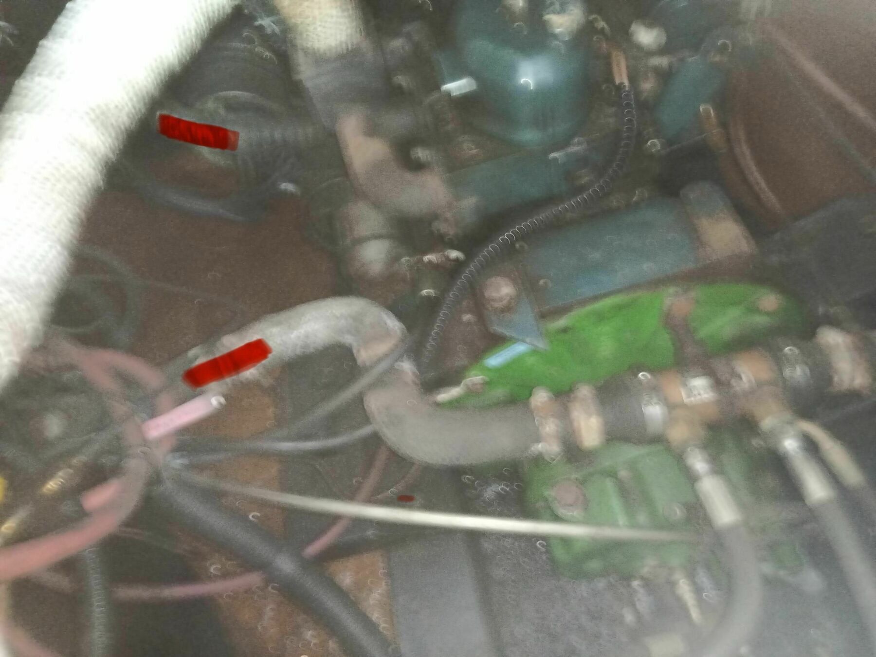
So the two "red" hoses will be connected either directly by the convoluted hose or via a second skin tank.
@BlueStringPudding No bilge diving for you today please, just wait till you have some help.
-
@Tony Brooks I didn't mention clamping the pipes in my earlier post because it looks very much like the hoses are the same age as the engine; might be a bit risky. Certainly looks self bleeding.
-
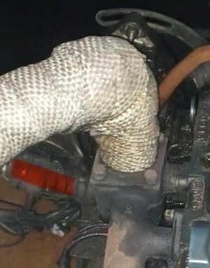
@Tony Brooks said ."It looks as if a plain hose on the oil cooler changes to a convoluted hose that Eeyore has marked in red. That change MIGHT account for the hose clips he mentions."
Ahh yes, could be. Looks to be a bit tight in there.
@Tony Brooks said. "Apart from the cylindrical remote from the engine coolant header tank and the use of the CH Header tank as an expansion tank with the shared pipe I can't see anything odd or unusual about the system."
Agreed. I quite like that the neck for the filler on the blue cylinder has been fitted at an angle so that there is always an expansion gap above the coolant when filling from cold.
-
@BlueStringPudding I've just been on a bigger screen, and this looks interesting. I think I can see 6 or 7 jubilee clips. Perhaps a photo of this if possible. Wouldn't be surprised if this is a twin skin tank set up at this point.


.png.350c76265e362269dd7d13024569d5b1.png)
cav ac203 alternator question
in Boat Equipment
Posted
60/80 amp inc every possible option