Craig Shelley
-
Posts
60 -
Joined
-
Last visited
Content Type
Profiles
Forums
Events
Gallery
Blogs
Store
Everything posted by Craig Shelley
-
I totally agree. But often as we try to achieve higher performance, the complexity has a tendency to spiral upwards. In this case I believe we are still seeing the ramifications of design decisions for automotive systems where cost would have been a very significant factor. The voltage surges hadn't used to be much of a problem when the only loads were bulbs, relays, ignition coil etc... The radio was more sensitive, and It was far more cost effective to build the surge protection into the radio rather than into the alternator. As time has moved on, there are now many electronic gadgets connected to the 12V supply. The automotive industry decided that every device connected to the supply should incorporate the surge protection, and published standards such as ISO-16750 to define the test scheme. It's quite a harsh set of tests, one of which (load-dump) defines a pulse of over 100V. The only problem is that the market is now flooded with a lot of cheep kit which won't come close to meeting these specs. e.g. knock-off mobile phone chargers. The industry has started to recognise that designing the surge protection into every device is no longer a cheap get-out, and the problem needs to be remedied at source. The next generations of vehicle alternators therefore, inevitably will be more complex.
-
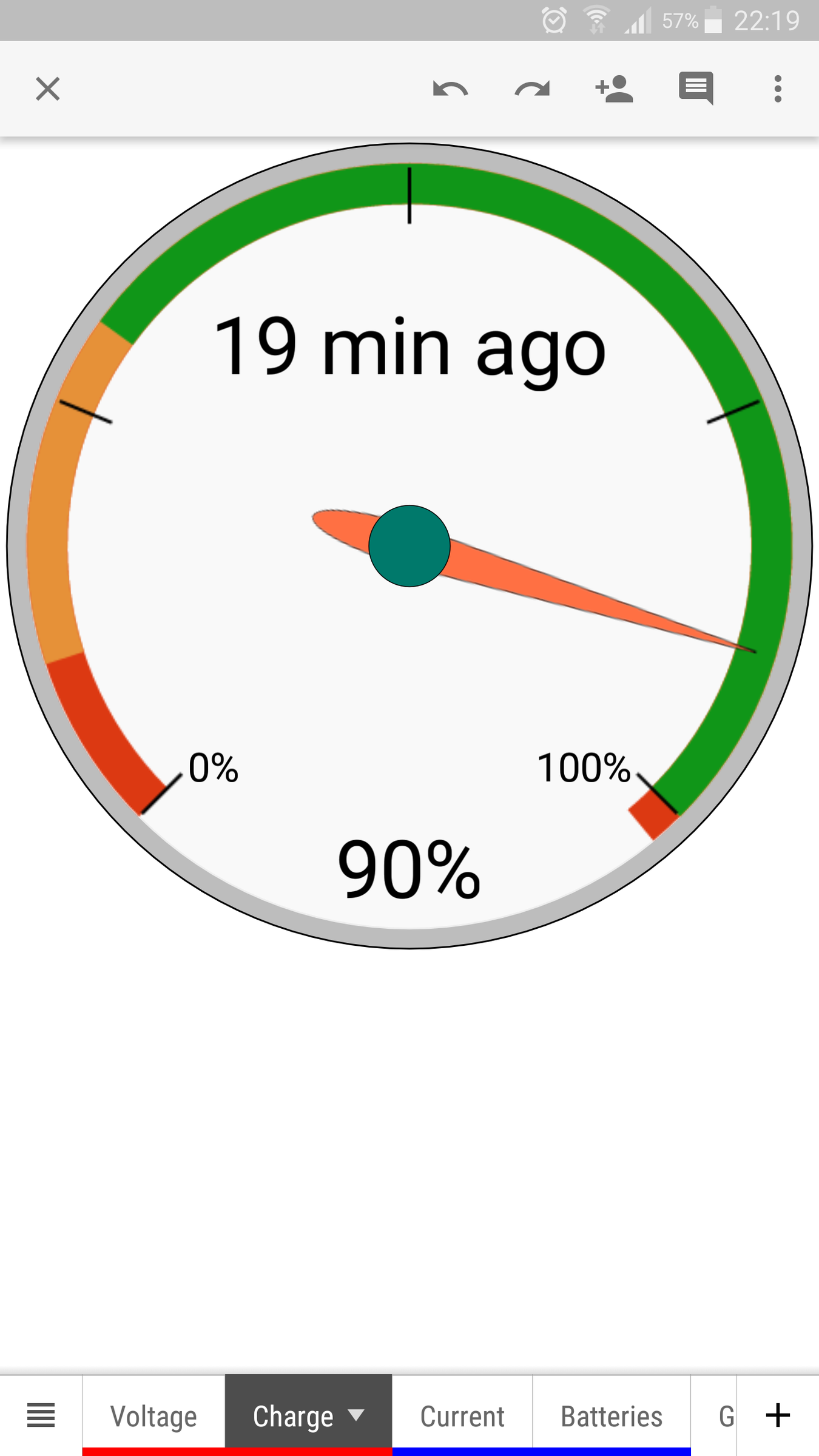
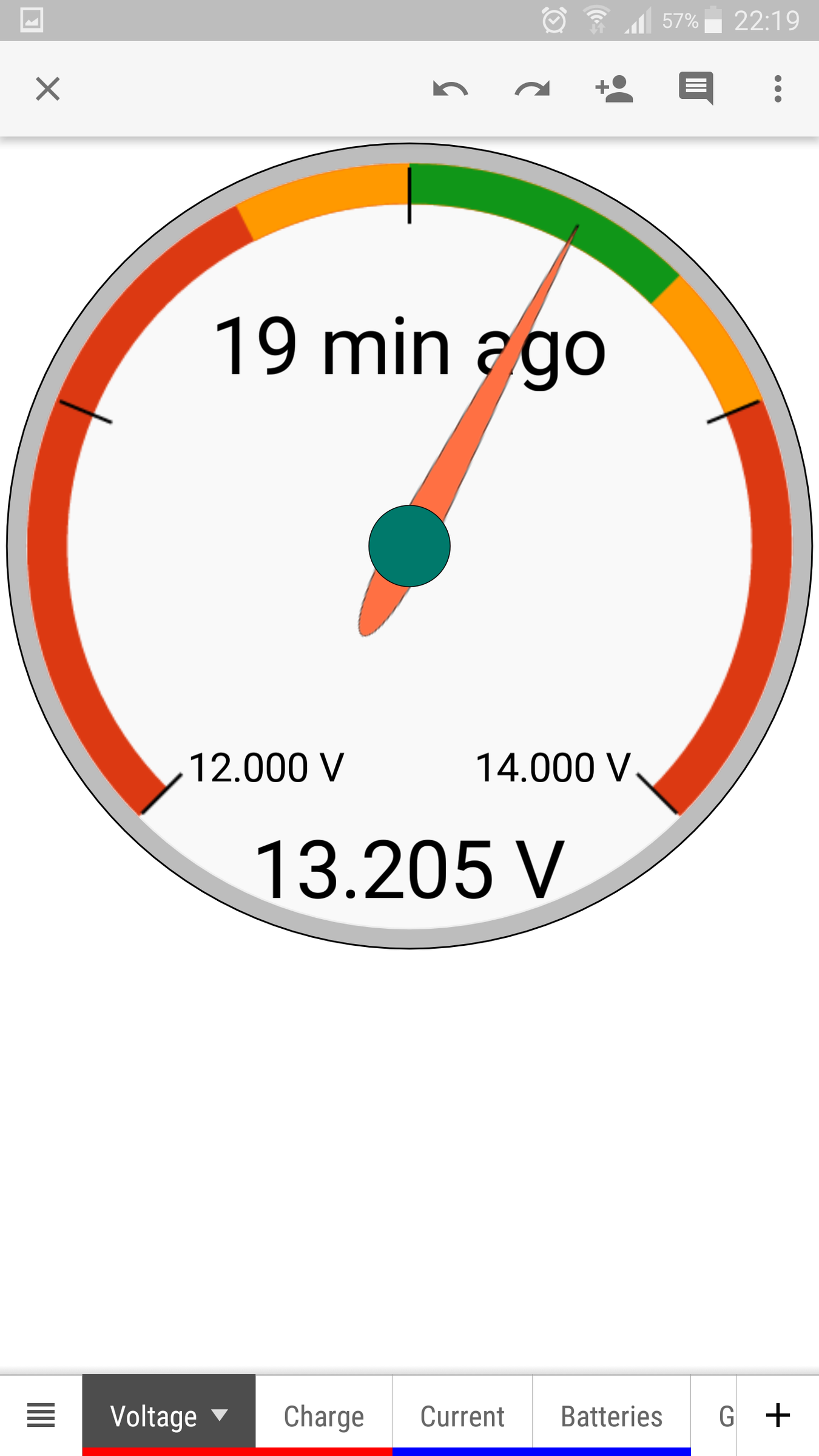
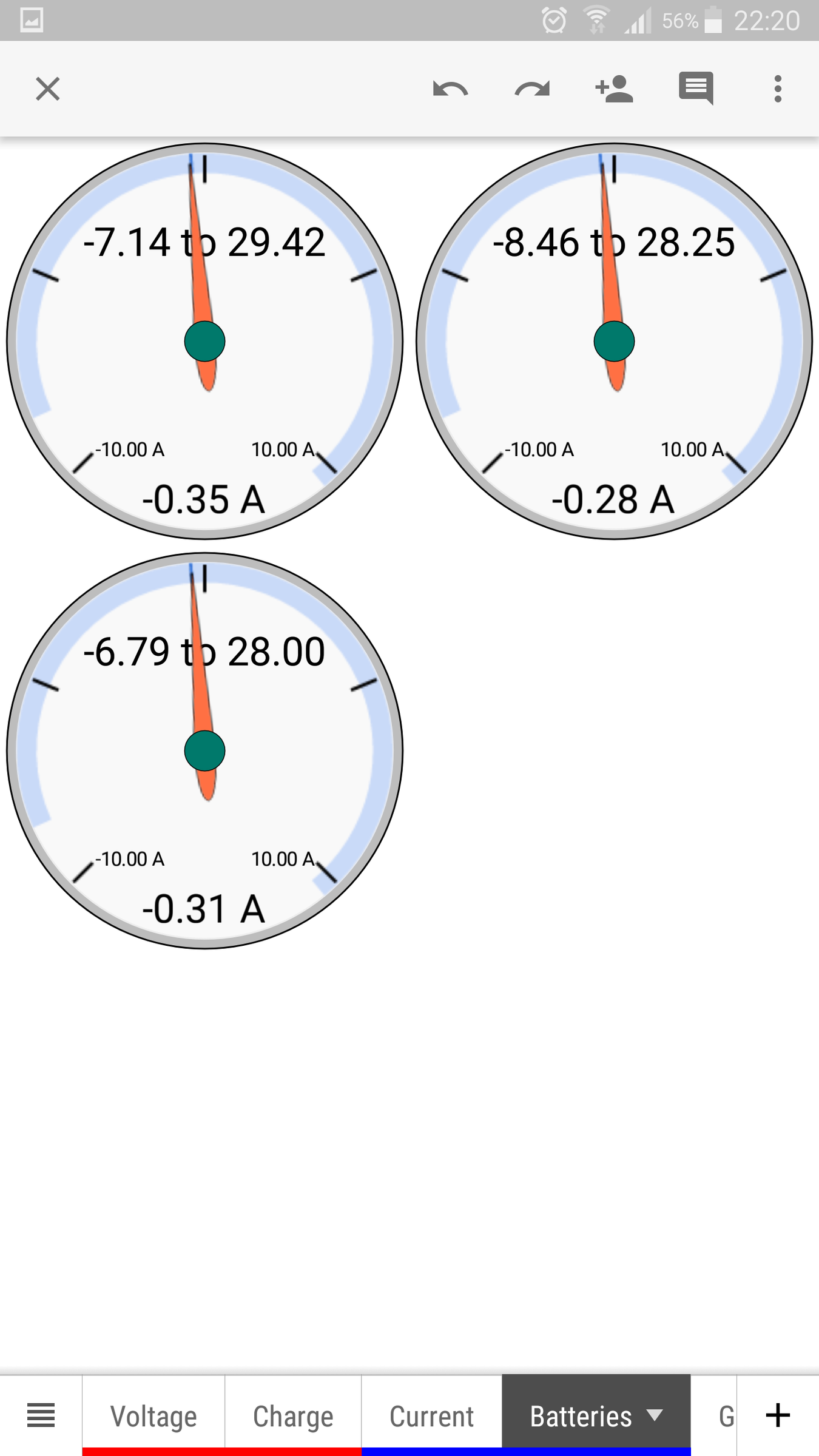
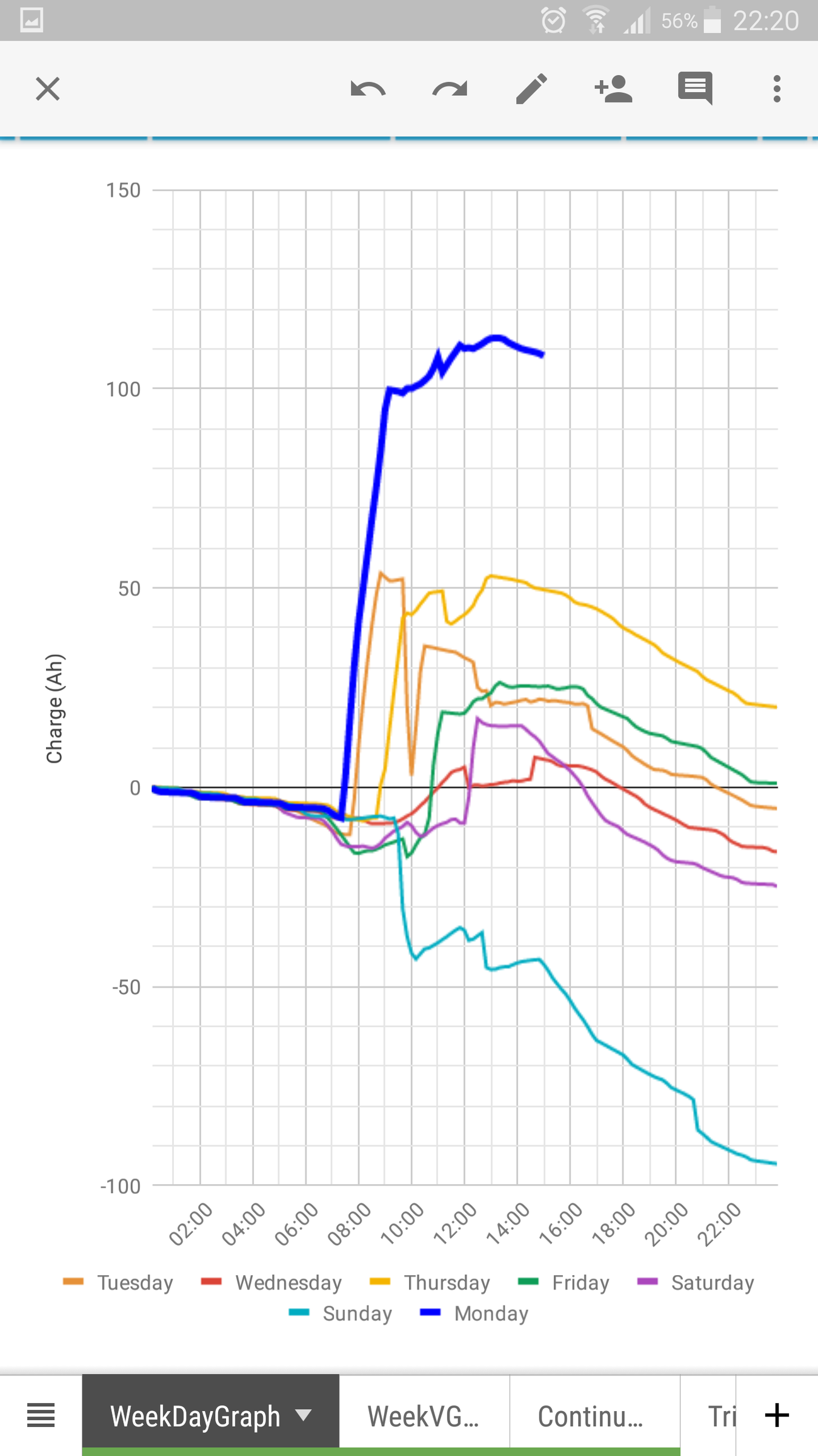
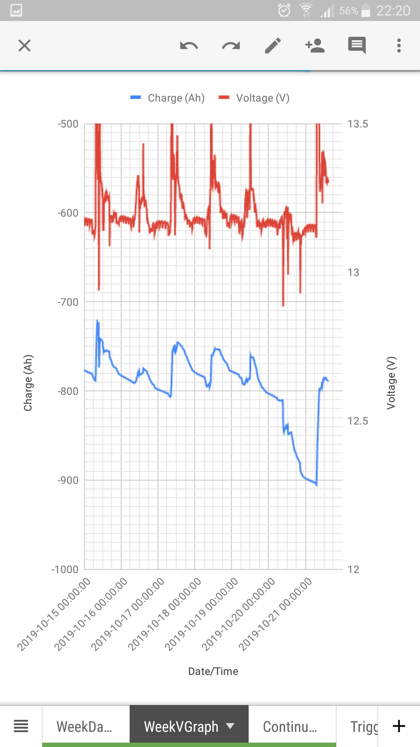
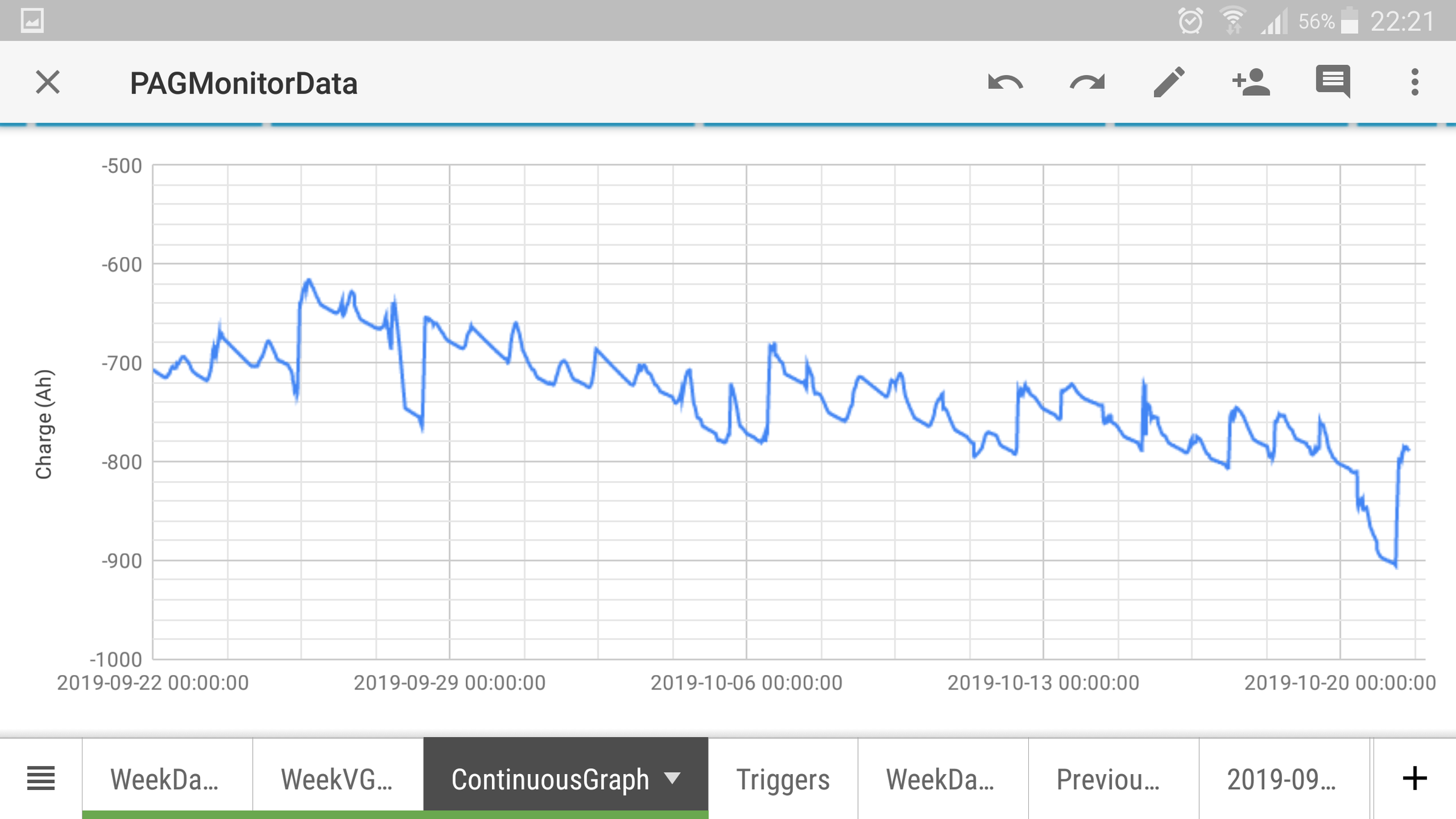
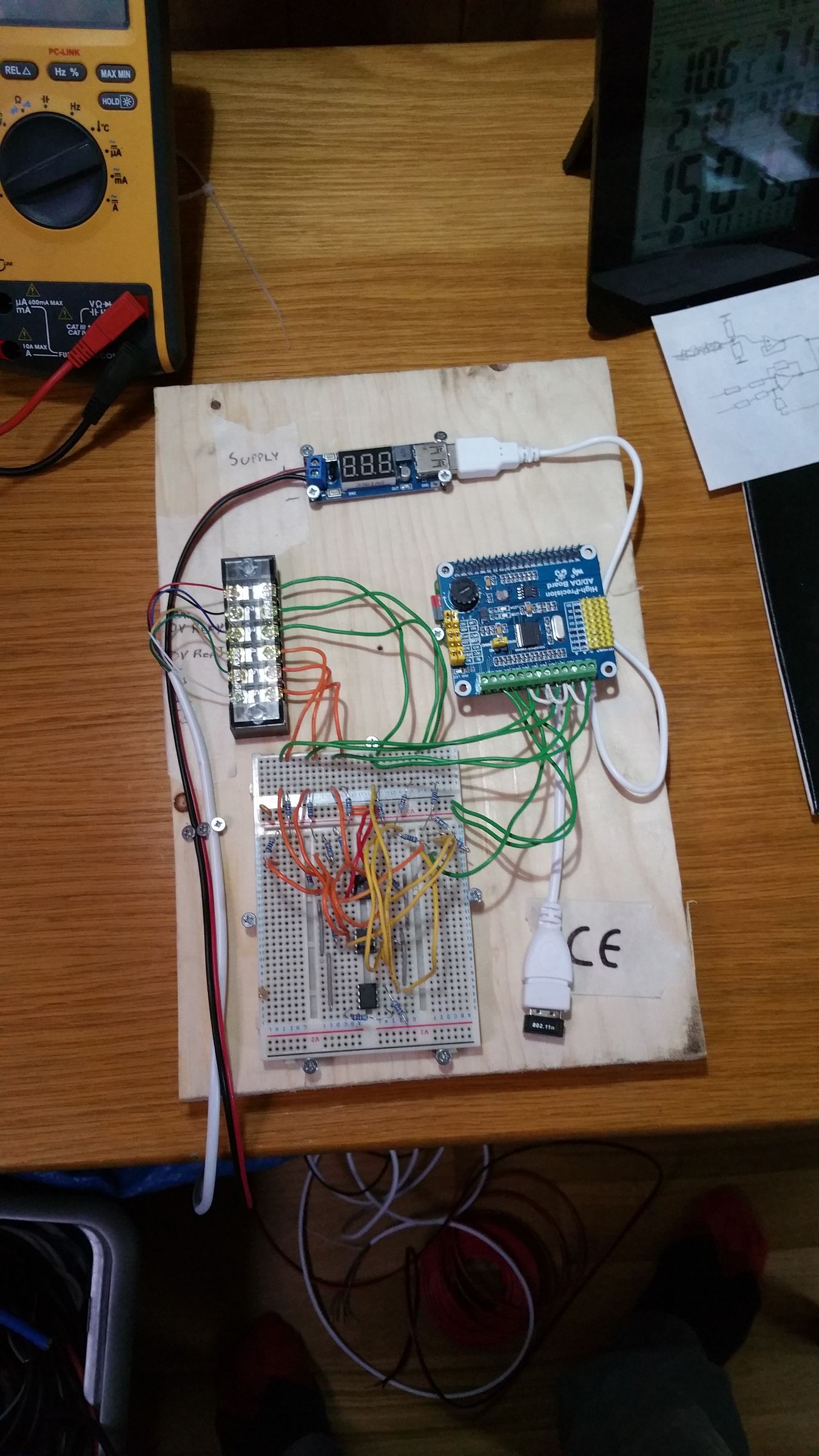
Sorry for the late reply... Too many hobbies For the curious, there are a few screenshots of the monitoring system which was bodged together over a weekend using an RPI zeroW, a 24bit DelSig A/D (ADS1256) and google sheets. For convenience i'm using a board made by WaveShare, which just plugs into the RPI and has screw terminal connectors. Cheaper clones exist. After a year, I'm afraid this bodge has still not been turned into a proper system and parts of the circuit are still on breadboard. Despite this, it has been surprisingly reliable. This system just monitors 3x battery currents, and the overall voltage. I would like to expand it to monitor the individual cell voltages + temperature. Currently the cells have no means of balancing, so we occasionally do a manual spot check with a DMM. After 2 years of use, they have remained sufficiently balanced that no intervention has been needed. From the continuous monitoring of battery current, it's possible to derive the charge and determine an estimate of the state of charge. The data is plotted on a Google sheets chart, which can be viewed on any internet connected device with display. This system is far from perfect, but you have to start somewhere. I'll cover the alternator mods in a different post.

-
We've faced very similar issues as the design has evolved. The boat was already fitted with a sterling alternator controller, which was not compatible with the new battery type. Luckily, this contained a PIC, so we've written new firmware for it. The batteries are switched via a BlueSea Systems remote switch, which can easily be incorporated into a battery protection scheme. A side effect is that this leaves the alternator vulnerable to load-dump if the batteries ever become disconnected. So we've installed a crowbar to short the alternator phases if a voltage transient is detected. There's a YouTube video demonstrating the testing of the crowbar. Battery monitoring is via a raspberry pi.
-
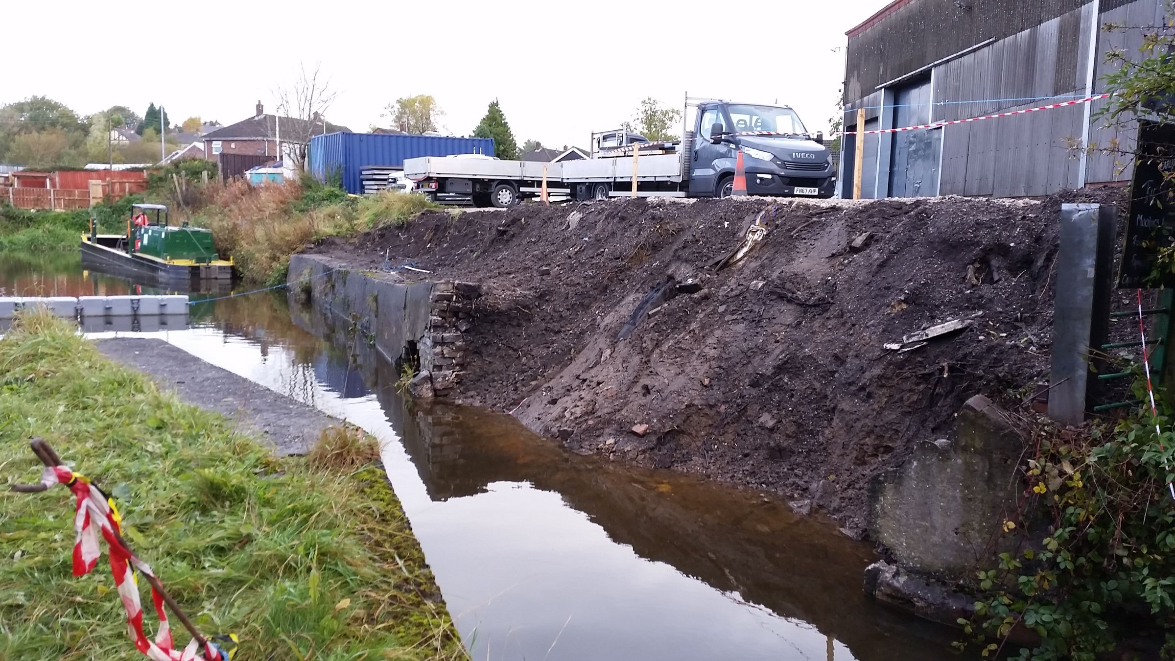
Currently awaiting CRT to open the navigation. Doesn't look as if there's any rush to fix it.
-
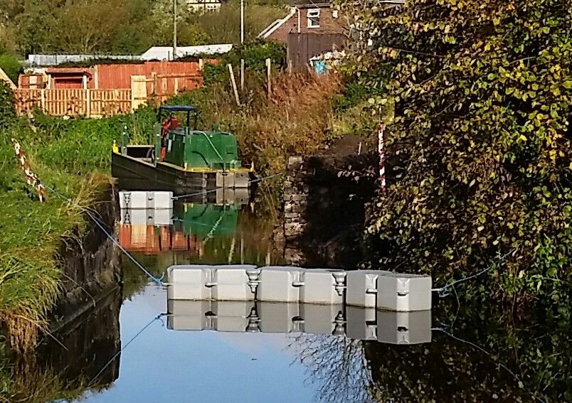
We went by on Saturday 5th, and wondered what they were doing with all of those concrete sections perched on top of the bank. They still had a fresh concrete dust smell. Saturday night it rained quite heavily. Going to the Foxley without a coat wasn't a good idea!
-
Unable to Stop the Fuel
Craig Shelley replied to Craig Shelley's topic in Boat Building & Maintenance
Perhaps your fuel injection pump has a different design. In our case the fuel must have been back flowing through the pump. Another thing worth noting is that the fuel which has back-flowed through the system has effectively bypassed all 3 fuel filters. The filter we were attempting to change was the on-engine filter, which is the last in the chain. -
Unable to Stop the Fuel
Craig Shelley replied to Craig Shelley's topic in Boat Building & Maintenance
Would fitting a non-return check valve instead of another manual shut-off valve, be an acceptable solution? -
Hi, We had a bit of a surprise while changing the on-engine fuel filter today. I thought I'd share it to hopefully prevent someone else from having the same mishap. Despite turning off the tank fuel valve, fuel kept flowing from the engine fuel filter. It turned out that the fuel tank had been over filled above the height of the fuel return line, which doesn't have a shut off valve. We believe the fuel was back-feeding through the injector pump. I can't find anything in the BSS which mitigates against this scenario as in my opinion being unable to stop a fuel supply is a hazard. The fuel had recently been filled, but the level appears to be sensible. Looking at the side of the tank, it's obvious that the level is above the fuel return line entry point. Is there supposed to be a shut off valve or check valve in the fuel return line to prevent this? Regards, Craig
-
Vetus M4.5 coolant temperature sensor?
Craig Shelley replied to Rivelin's topic in Boat Building & Maintenance
The blue wire is the over heat switch. It sounds an alarm on the panel if the engine gets too hot. The manual describes how to test it. Vetus don't usually provide engine temperature gauges on these engines, which I think is a bit ridiculous. The bolt next to the hose is the logical place to install a temperature sensor, with the appropriate thread adaptor. It looks like someone has already installed a sensor on your engine. The bolt on the top with the blue lug crimp is being used to provide the 0V reference for the gauge. That bolt is actually a coolant air bleed, which supposed to be removed when filling the coolant for the first time to avoid getting air lock. The wire is obviously missing from your sensor. I would say the stud appears to be broken off the sensor too. As there is no provision for engine temperature sensor in the engine harness, we have cable tired our wires to the hose in order to provide a strain relief. My guess is that someone installed the temperature sensor onto this engine, but didn't adequately provide a strain relief on the cable. The cable has at some point been snagged, and ripped the stud out of the sensor.