twelveeyedfish
-
Posts
134 -
Joined
-
Last visited
Content Type
Profiles
Forums
Events
Gallery
Blogs
Store
Everything posted by twelveeyedfish
-
Ah, yes there it is! Maybe I will get in touch and see if there's a response. Perhaps it can be resurrected - if it were me, i'd be pleased if someone were carrying it on. For now, this seems to be the index page - it's all a bit spread out as it grew organically but there are some treasures in there which are relevant to boaters and caravanners alike. https://web.archive.org/web/20150423022649/http://www.satelliteforcaravans.co.uk:80/index.htm
-
Heartbreakingly, I am guessing that the guy who ran the website "satellite for caravans" has now died. He was an older man but he had the most amazing webpage ever regarding satellites, alignments and their relative transponders. Unfortunately, that website doesn't seem to exist now. Being an engineer, I lapped up all the information and understood it and much to the annoyance of all those who see me do it, I can now set up a satellite dish with a compass and no box virtually perfectly. Usually I just use the gauge on my (Pace 430N) Sky Plus box or Humax PVR. I don't often do it on the boat but I do have to do it on caravans and people's houses! For some time I have been thinking about recreating that information - it will take a long time to get it as detailed as he had it (it was a fascinating read) but it sounds like there might be a call for it? A winter project perhaps.
-
I use a 1 kW immersion heater which I got from here: https://www.heatrodshop.com/product-category/immersion-heaters/domestic They have the full selection of shapes and sizes unlike most people who only sell the version above - my vertical calorifier needs the 27"er and they seem to be a bit of a sod to find. The prices are a bit steep compared to a normal one but they're fully conventional regarding replacement thermostats and things and of course made in the UK.
-
Lister LPWS3 fuel system bleeding
twelveeyedfish replied to colmac's topic in Boat Building & Maintenance
Hallo! this is getting fascinating! I was able to deduce visually from the service manual that it wasn't a true marine engine but it has been providing power for over 20 years in this boat. I do wonder how you might find out what it's special build purpose was! I doubt all this was special build though. My suspicion might be that the flywheel ismodified or the attachment to the gearbox housing. I have never been able to place what the gearbox is at all. Erm, the only part I can actually find to buy is the difficult part... <http://www.ebay.co.uk/itm/like/232152617758?lpid=122&chn=ps&adgroupid=13585920426&rlsatarget=pla-75952154106&adtype=pla&poi=&googleloc=9046677&device=c&campaignid=207297426&crdt=0> though given what you say, this may be a replica part. Of course, the fittings are all going to have been modified to accept this rigid hose. I'm going to end up with a greasy set of spanners! Thanks for all your comments. This is helpful. I'm off work on Friday so I will call to discuss if there are any bits which we can get hold of! -
Lister LPWS3 fuel system bleeding
twelveeyedfish replied to colmac's topic in Boat Building & Maintenance
Thanks Richard, It looks like conversion back to stock might not be that trivial, unless LP spares can provide everything! I didn't realise 1991 was "early"! hah. I will just add though that Item 12 on the illustrations I have seen connects through 12/13 back to the leftmost point of Item 1, the low pressure rail. Doing this would severely tidy up the engine bay! Is this spares document available to buy? Presumably the part numbers are listed elsewhere. The exploded diagrams are really useful! -
Lister LPWS3 fuel system bleeding
twelveeyedfish replied to colmac's topic in Boat Building & Maintenance
I had the same thought. I'm not sure why they never did meet the requirements but I only have a current BSS guide! The fact that I thought rubber hoses were against the rules was just something I had in my mind from a conversation a few years ago. -
Lister LPWS3 fuel system bleeding
twelveeyedfish replied to colmac's topic in Boat Building & Maintenance
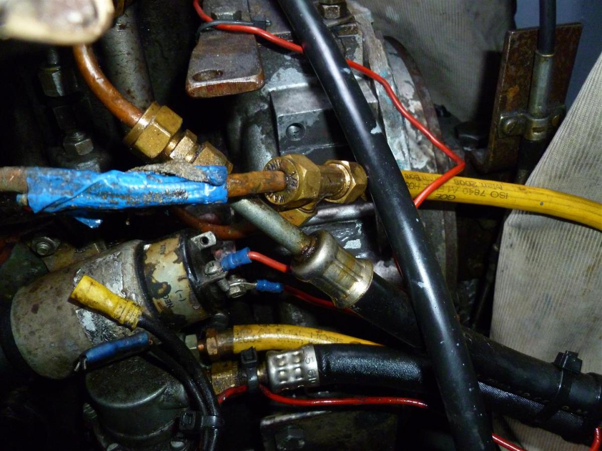
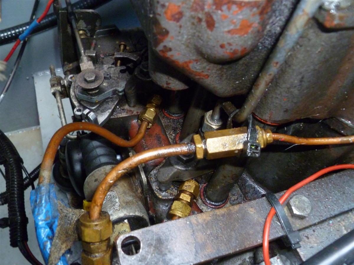
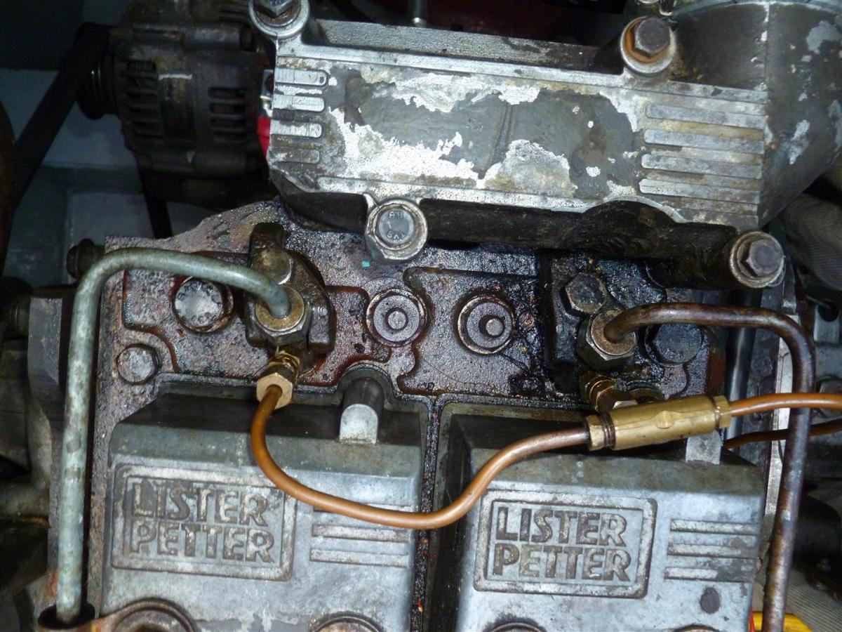
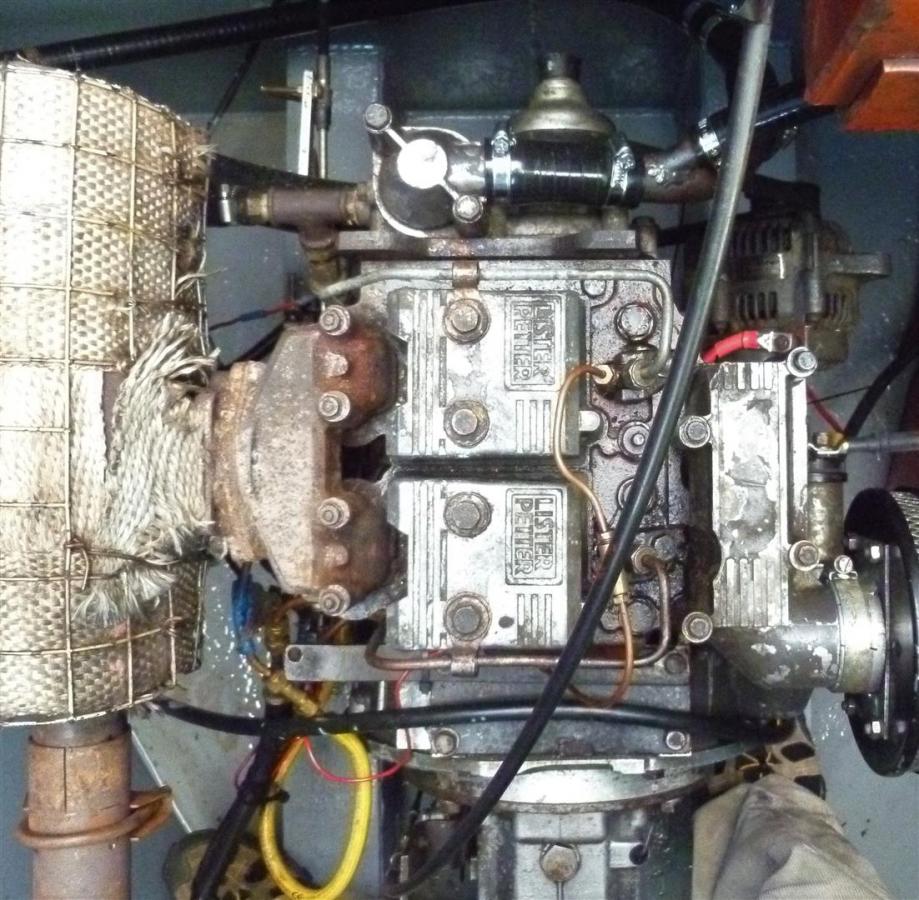
Here are the images - the "T" is the split from the output of the lift pump into the injector pumps. The flexible black hose is the return from the spill rail, brought to the same place before the fuel lines run together back to the tank. The diesel injector pumps are just the weird way they're set up. It's hard to see as set up. If you need more, just say. The spill rail is just a detailed picture of the spill rail from the injectors, showing the injector plumbing. This is just an overall picture to show position etc. All I will say is that the diesel is the result of the last few days. Not a leaky engine that's falling apart! It's a mess I've created!
-
Lister LPWS3 fuel system bleeding
twelveeyedfish replied to colmac's topic in Boat Building & Maintenance
Well, in a hurry I can't work out how to put a picture up. But the engine number in full is: 410061LPW2A902 I presume there's a guide on posting images so I'll go take a look for that now -
Lister LPWS3 fuel system bleeding
twelveeyedfish replied to colmac's topic in Boat Building & Maintenance
Hello! I'm back in the warmth of England again (no, that's not a joke). Thanks for the pictures; I think the engine I have is a bit more modern but the pattern fits. What I can see of the parts are in the same general places. Tomorrow in the daylight I will take a few photos of my own and get that engine build number. The photos may help some other people too so it's probably worth it. Thanks again -
Lister LPWS3 fuel system bleeding
twelveeyedfish replied to colmac's topic in Boat Building & Maintenance
Either way, this does not seem to be what the engine should do when configured as stock. But yes, I'm not sure how it becomes self bleeding if it has feedback like that! More mysteries! -
Lister LPWS3 fuel system bleeding
twelveeyedfish replied to colmac's topic in Boat Building & Maintenance
Judging from pictures, this apparently mythical hose is missing! Also, I've always been confused by the fuel exit... so let me entertain you a little more... Fuel tank, offboard fuel filter, lift pump, injector pumps, rigid hoses to injectors, outflow from injectors through copper brake type hose back to fuel tank. This always seemed a little wrong to me... and it seems like it should be this: fuel tank, (offboard fuel filter), lift pump, onboard fuel filter, injector pumps, rigid hoses to injectors, outflow from injectors back to inflow to injector pumps. This would severely tidy my engine bay! It would also stop warm fuel from being returned to the fuel tank and promoting the growth of biological annoyances though I seem to have opened my own can of biological annoyances (worms!), albeit a fun one! I'm not too afraid of cost - I live for a love of machinery; like you I'm an engineer but I design electronics and write software. This is much better than watching the X Factor and still cheaper than a TV licence. -
Lister LPWS3 fuel system bleeding
twelveeyedfish replied to colmac's topic in Boat Building & Maintenance
Hello Richard, That information is on the engine, but I don't have it to hand. I am away in Germany for a week working now but if there's magic that you can do with it, I'm happy to provide it! I realise now how rude my previous comment seemed! This is what you get for being half asleep! Sorry about that! -
Lister LPWS3 fuel system bleeding
twelveeyedfish replied to colmac's topic in Boat Building & Maintenance
Well my Blizzardino friend, after trawling through a bunch of photos and exploded diagrams, you're right! There should be a fuel filter exactly where you say. And there isn't! So, that issue aside, which I will resolve... in due course! I'm going to have to track down part numbers and new pipeworkage. Thanks to your confidence building however, the engine runs! Nothing you said really helped because nothing was really wrong. But I did as you suggested and unplugged the pipes at each level. In reality however, the fuel just splurged through anyway - but you might expect that from a diaphragm fuel pump perhaps. I presume the non-return valve is really the stop solenoid... (there's definitely nothing missing except the fuel filter). I'm also not massively confident that one of the injectors is receiving fuel, but it's late and dark so I will reserve judgement! It sounds like, although this engine will run on and on regardless right now, I might need to sit down and have a pint with someone who knows about these old fashioned engines and how they work. Thanks for your comments throughout the day. Much appreciated. -
Lister LPWS3 fuel system bleeding
twelveeyedfish replied to colmac's topic in Boat Building & Maintenance
Having looked into it a little further since you originally raised the point, this doesn't appear to be specified for an LPW2 engine. But now I come to write this I'm not sure I gave that level of detail originally. I can't see it as a serviceable item in the manual. Not to appear as if I am arguing. I am just at work rather than in front of an engine! I have seen small (tiny) paper filters on some other more modern engines however. I am guessing this is what you mean. The pipework on the LPW between the regulator mechanism to the injectors is rigid. So... perhaps the on board filter system is fuel, fuel pump, filter, regulator injector? Even then however, the fuel filter will be a standard oil filter sized affair (as although it's not fitted to the engine mount, it is the same housing attached elsewhere). Oh, the mysteries! -
Lister LPWS3 fuel system bleeding
twelveeyedfish replied to colmac's topic in Boat Building & Maintenance
Oh... there isn't one! Nor is there space to put one. There's just the standard fuel filter which is normally mounted on the engine but is mounted elsewhere on my boat just for fun! It goes fuel pump -> regulator -> injector. That's what all the diagrams say too. That's why I had originally disconnected at the injector itself to see if I could see fuel spewing out. -
Lister LPWS3 fuel system bleeding
twelveeyedfish replied to colmac's topic in Boat Building & Maintenance
Thanks Blizzard, I'll give that a go. I didn't think there was much resistance to my finger on the lift pump. Knowing that a good squirt should come out certainly helps with the diagnosis. I wasn't too sure on the quantities involved. I did wonder if I wasn't catching something when pressing the lift pump lever though. I'm a shade confused by your suggestion to remove the inlet or bleeder on the fuel filter - if I do that then the fuel will just squirt out strongly by the force of gravity (this happens, it's how I primed the fuel filter). The fuel pump is after the filter. -
Lister LPWS3 fuel system bleeding
twelveeyedfish replied to colmac's topic in Boat Building & Maintenance
Hello, nice to be able to resurrect an existing thread that answers my question! so thanks. However it didn't work so I get to carry on a bit! I have an LPW2 engine on which I recently changed the fuel filter and now I have done this, I cannot get the dratted thing to start. The fuel filter is primed but owing to a misunderstanding with a piece of dirt, air got in. The manual is pretty clear about how to prime the system as are the guides above - all systems go, operate the lift pump a few times and away! I have operated the lift pump a few hundred times and I can't see anything spewing out anywhere, especially air! Even with the fuel connection to the injector removed, nothing is coming out. Unfortunately, this also seems to be the case whilst the engine is turning. Does anyone have any thoughts or can they point out the thing I might be missing. Maybe the fuel pump is kaput, though the engine was running before I started this operation! I'm pretty confident with these things but I wont undermine the experience of you lot who also have them! Maybe it was just the draw of the engine that was pulling in fuel previously, aiding a weak pump. Thanks! -
Control cable routing
twelveeyedfish replied to twelveeyedfish's topic in Boat Building & Maintenance
Hello all, busier day than expected at work so I have only just had a chance to look at these. Yep, for now I'm looking for an imitation of what's already there but if nothing is quite right I will revisit those other posts (I too had considered using cable grommets but I already have a massive hole in the deck). Just to clarify, the hole in the deck is circular (and modifiable if required) but the hole in the grommet was 8 shaped as in two holes side by side for the cables. Thanks for the links, there are several things I imagined would exist but couldn't manage to work out the google words to find them! You've also pointed me at some products I didn't know existed but might be suitable and elegant too. Not spotting "two holed grommet" was a bit embarrassing for me though. Much appreciated! -
Hello folks! In the process of doing standard maintenance on the boat I want to replace a little rubber gland through which pass the control cables from the Morse control. The control cables pass vertically through the floor of the stern decking and down to the engine and this is a point at which water drips down and into the engine bilge. With time, this rubber gland has perished and try as I might, I can't find anything whatsoever to replace it with, be it similar or otherwise. Now that it's dark when I get home from work I'm also struggling to take a look at other boats nearby! This one is 1.5-2 inches across and has two holes in it for the gearbox and throttle cables (like a figure of 8). It fits into the metalwork of the boat like a bung that home brewers use (I've already considered this, they're too small!). It definitely looks like a "part" and not something that someone has skilfully whittled from a lump of rubber. I'm happy to take a picture if it helps but I dare say some people will already know what I'm talking about and have something in mind. So thanks as always. But... has anyone got any ideas?!
-
Painting an engine bilge
twelveeyedfish replied to twelveeyedfish's topic in Boat Building & Maintenance
MJG, I'm inclined to agree in some ways. In my mind a boat that has a filthy engine bay may or may not have a well serviced engine. However, a well serviced engine bay that is boat maintenance in itself to me. It's a messy place with some engines - but if it's so putrid with oil and diesel, even if only from oil change spillage so that it's not practical to get into it, then that is a sign of poor maintenance. If it's rusty and in need of some love, that's poor care, too. The condition of your engine bay may have been appropriate to your selling price (and not just the condition of the engine), but my boat has been so well cared for over its life that I am simply maintaining it to the standards to which it has become accustomed. If it were a state, it would be incongruent with the condition of the rest of the boat. I wish to maintain that. The truth is, I have as much enthusiasm to do it as you seemed to! haha. -
Painting an engine bilge
twelveeyedfish replied to twelveeyedfish's topic in Boat Building & Maintenance
Yeah, I have this issue with danboline and primer! I'm not sure it does anything but maybe it just helps the application be more reliable. I doubt primer gets surface condensation as easily as bare steel which might make the Danboline application more reliable and consistent in some weather conditions. Like I said, my bilge is in incredibly good condition after 20 years and I'm only doing this as a matter of maintenance and to get some painting skills for the roof which actually does need painting. -
Painting an engine bilge
twelveeyedfish replied to twelveeyedfish's topic in Boat Building & Maintenance
Ah, yeah I saw that thread - didn't answer my specific question about the Danboline needing primer so I started my own. Your bilge was grotty to start with. Mine is (after 20 years) still pretty tidy! and rust free. I think it's worth doing though. You need to keep up to all painting really. Is the second "black" picture with the Fertan? Haven't found anywhere selling the primer I want yet. Something for tomorrow evening I think. Can't use that till after the Fertan anyway. -
Painting an engine bilge
twelveeyedfish replied to twelveeyedfish's topic in Boat Building & Maintenance
Well, you can go over the top for an extra 20 quid or you can do the whole thing again for 50. -
Painting an engine bilge
twelveeyedfish replied to twelveeyedfish's topic in Boat Building & Maintenance
Ah, that stuff. Okies I'll get some of this stuff on order, thanks. Especially about the primer for the Danboline. -
Painting an engine bilge
twelveeyedfish replied to twelveeyedfish's topic in Boat Building & Maintenance
Morning BEngo - thanks; I've not read the tin as I haven't ordered it yet(!) but the web page says nothing apart from the colours it's available in. I presumed it would need a primer but the total absence of mention on the webpage made me ask! I thought Gunk might have been useful. It might be overkill for the bit above the swim where the batteries live but it's not a massive area. However I'm not sure what "washing soda" is... (maybe it's my age!)