


LL 1975
-
Posts
29 -
Joined
-
Last visited
Content Type
Profiles
Forums
Events
Gallery
Blogs
Store
Posts posted by LL 1975
-
-
17 minutes ago, MtB said:
From the manual:
In-Line Fuse Assembly
Purpose
The purpose of this fuse is to protect the pump from
serious damage in the event of system blockages,
therefore please ensure all valves are fully open before
operating the pump.
Connection Instructions
Insert this fuse assembly between the positive terminal
on the pump and the positive feed wire.
Note:
1. If the fuse blows check:
a) all system valves/stop cocks are open.
b) the inlet and outlet nipples are not blocked
c) the remainder of the system is not blocked in any
way.
2. Fuse rating for BP1552 (12v DC) pumps 5 amp
automotive. Fuse rating for BP2554 (24v DC) pumps
2.5 amp automotive
To control the pump an in-line switch should be fitted
between the positive live terminal on the battery and
the positive lead on the pump. If using an automatic
switch (such as a float switch) an isolator switch
should be fitted.
https://www.manua.ls/whale/gulper-220/manual
super commenting here - thanks indeed!
1 hour ago, BEngo said:What size is it? Length x diameter in mm.
If it is the cylindrical glass type a Google on length x diameter numbers and "5A glass fuse" should find some.
I can see no reason to need a slow blow fuse.
If you are not just seeking spares, you should really investigate why the Gulper has blown its fuse.
N
I am happy the gulper came across some debris which accidentally got past the plug filter gummed it up and caused it to overload, I've since cleaned hoses and checked the pump is operating normally (gland not ruptured etc) by holding the fuse contacts together. So yes i am looking for spares and am confident I've found the problem.
57 minutes ago, bizzard said:A card of fuse wire usually has 5amp wire on it. Twist a bit of it around the prongs for the time being.
didn't they discontinue them after the Boer war?
-
40 minutes ago, Tracy D'arth said:
5A would seem to be a bit under-rated to me for a Gulper. Most 12v pumps have 10A fuses. Is it 12v or 24v?
12v
-
I cannot for the life of me find a like for like replacement for the fuse for the 220 whale gulper. I read that it takes a '5 amp automotive fuse', however it's a cartridge fuse shape but longer than standard household fuse and I am unsure if it is a slow blow or not. Can someone help? I'd love to get my hands on a pack of 10 so I can label them in my fuse box and never have to worry about it blowing again....... thanks in advance! I cant believe I've written slow blow in the internet.....
-
 1
1
-
-
8 minutes ago, dmr said:
How many hours has this engine done and has it been regularly serviced etc (if you know) ?
Does it sound ok or any nasty knocking sounds?
Hours around 2000, good service history around once a year after initial 50 hours. Not sure about oil filter mind you, oil was def changed in the last 3 services.
-
4 minutes ago, ditchcrawler said:
What oil are you using?
The correct non synthetic one - reason I’m so confident is I checked with Engines Plus to get the right one and had to order it delivered by new era to get the right one in large quantity (25 litres so I don’t faff around next time).
-
Canaline 52HPCan any one think why my engine which runs at between 1 and 2 oil pressure (standard canaline panel) after about an hour slightly loses oil pressure (dropping down to around 1 ) which causes the oil pressure alarm to sound? Funnily enough increasing revs with the engine out of gear at this point increases the pressure and stops the alarm sounding. However bring the throttle back at any time after this and the pressure drops again and the alarm sounds. Oil level looks fine. Recently changed the oil sender which didn’t change anything.
-
35 minutes ago, Alan de Enfield said:
I'd suggest reading the BSS requirements (available on the BSS website - I have them but they are too many Mb to post here), once read, phone the BSS and explain your plan and see if they agree, and if so, get them to confirm it in writing as any future examiner is likely to give you a BSS fail.
Any other course of action (including taking advice from some random guy on a forum) could result in a BSS failure and the cost of resititution
My reading is that apart from the drain hole, the locker must be gas tight up to at least the height of the top of the cylinder 'handle / ring'
Putting stuff in the bottom which could potentially move and block, or partially block, the drain is forbidden.
Is your boat post 1998 ?
If so then it should have been built with a gas locker to the ISO 10239 "Small Craft Liquified Petroleum Gas (LPG) Systems" and comply with the following :
8.3 Cylinders, pressure regulators and safety devices located below decks or in cockpits shall be mounted in cylinder lockers which, when closed, are vapour-tight to the craft interior and vented at the bottom by a drain of not less than 19 mm inside diameter or the equivalent area if not circular. The cylinder locker shall be openable only from outside the craft interior. Cylinder lockers located in cockpits may be openable from inside the cockpit if the locker can be opened only from the top.
8.4 The locker drain shall be run outboard, i.e. to the outside of the craft, and shall be ⎯ without sumps which can retain water; and ⎯ with the outlet at a level lower than the locker bottom and as high as practicable, but not less than 75 mm above the at-rest waterline and above the waterline at a heel angle of 15 degrees when in the fully loaded ready-for-use condition.
The BSS requirements :
The sides of every cylinder locker must extend at least up to the level of the top of the cylinder valves, or other high-pressure components where these are higher.
Up to the level of the top of the cylinder valves, or other high-pressure components where these are higher, the bottom, sides, and seams of every cylinder locker must be free of any:
• holes, e.g. caused by drilling, rust or cutting; or,
• cracks, splits or de-laminations; or, • missing or damaged welds at seams; or,
• other signs of damage or deterioration… …. that can be identified by visual examination to penetrate the locker to the interior of the vessel
Thanks Alan,
Appreciate the feedback including getting any changes confirmed by BSS - seems sensible. Aside from that - which i will do, based on the points you have pasted i think i am ok providing the painting of the locker doesn't affect the hole which it wont, anything i place on the bottom of the locker offers no possibility in its design to enable blocking of the drain hole and that any vent sits on the exterior side of the locker. The boat is 2014.
Best
Till
-
HiI have a gas locker on the port side stern locker of my widebeam. Fully compliant locker neatly fits up to two 13kg gas bottles etc.The locker has the obligatory hole toward the bottom which opens out onto the side of the boat to let any leaked gas from the locker empty out overboard.Problem with it is it’s sweaty as hell all year long and now needs a proper scrape treat with Fertan locker paint etc which I want to avoid having to do often so am keen to put a vent or 2 on the outside side of the locker (side facing the canal).Can anyone see anything wrong with this? It’s no where near a door or a window and will only aid air flow in the locker and in the case of a gas leak only allow the gas to waft overboard.I was also thinking of getting something to put on the floor which allows a bit of airflow (like that netting they up upside down glasses on a pub - but more industrial) something that enables air flow and prevents damp build up on the bottom and ensures the gas bottles aren’t just sat on the steel floor.Any thoughts welcome? Are vents a no no? If so why? Any specific best practice, regs, bss etc dictating this should or shouldn’t be done or should be done in a certain a way.ThanksTills
-
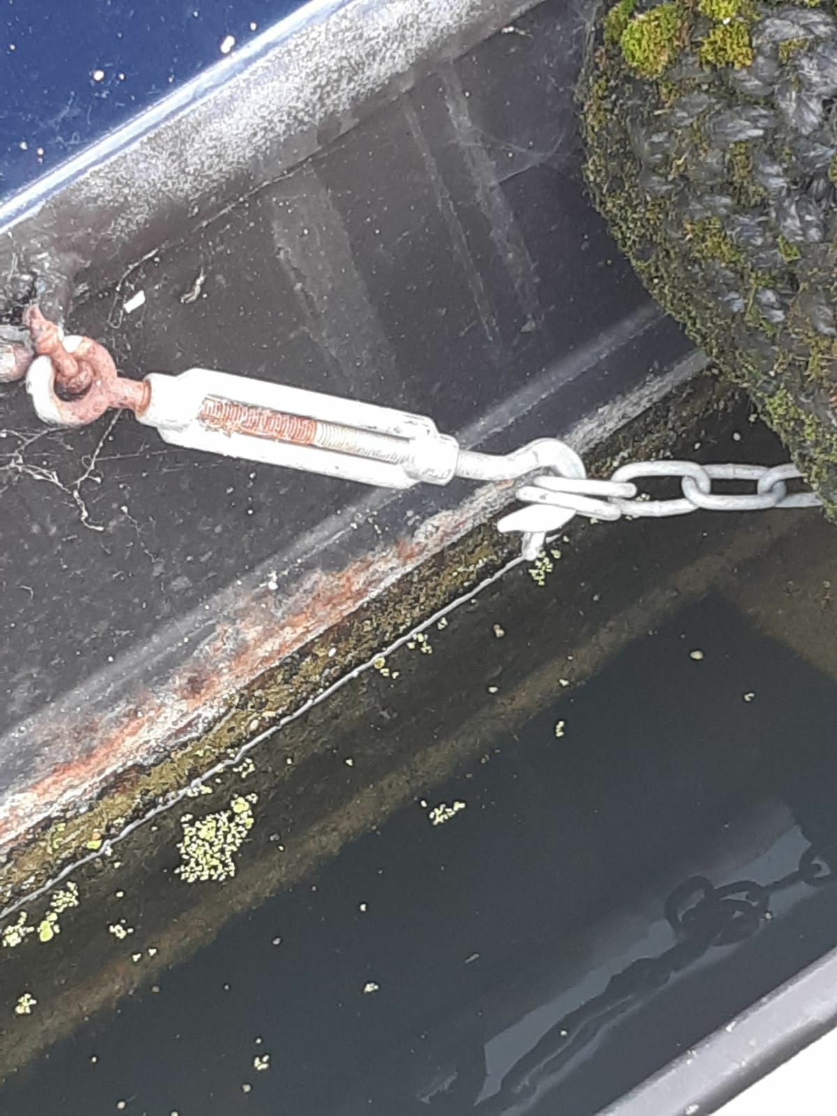
Hi Boatys,
could someone pls let me know what this swiveling, tightening, hooking shackle thing is pls, cant find them anywhere on the internet so looking for that special name.
Thanks so much

-
Canal world postDear enlightened friends.My Engineer has asked me to purchase:A threaded insert set for a 1/8" water temperature switch on a 42hp Canaline (EP910512).......... in his words he's tried and failed to drill out the old sender (which was sheared off accidentally by me) so will need to drill a hole, put in a thread insert and replace the sender with a new one (already purchased). With a google i can see kits that look like they would do the job but to be honest I am worried I'll get the wrong one, could anyone help please?CheersLL
-
Just now, Bee said:
It does sound like fuel and the filter(s) are the first thing to look at. Water in fuel is a sod and will make the engine shudder and knock, its not good as it does not compress in the cylinder. If the filters and fuel are clean then you could have a tiny air leak. I would not add new fuel to the tank until you are sure what's in the tank is OK or you might have to drain that out as well and the whole lot will end up mixed up and ruined.
ok gotcha, make sure fuel is good via fuel filter check and fuel test before filling with more fuel....
-
9 minutes ago, dor said:
Water in the fuel tank? 15%. Is getting quite low, and if the tank hasn’t been checked it could have a few litres sloshing about.
testing is drop a pipe down right to the bottom, thumb over the end, pull out then release contents (which should be a vertical section of the tank) into an empty ,cleaned out plastic bottle, let it settle and analyse (as in look at ? the contents?
4 minutes ago, Tracy D'arth said:Suck the tank dregs out with a wet and dry vac, a length of copper pipe in the sucking end will get you into the lower corner of most boat tanks.
Check you prop too, I've known poly bags cause some odd effects especially when going into reverse.
thanks - prop has been cleaned since this started happening so would prob rule that out as the sole cause.
-
Just now, nicknorman said:
As a general point, it is not a good idea to run out fuel. Diesel tanks tend to collect water and gunge which sits happily at the bottom of the tank, below the takeoff point. But when the level gets very low, this tends to slosh around and thus mix more and most likely some makes its way into the fuel takeoff pipe.
well received Nick
-
17 minutes ago, nicknorman said:
Or a slight air leak into the fuel system. I suggest filling up with fuel and see if that makes any difference. That may increase the pressure slightly in the fuel lines, so it is slightly above ambient instead of slightly below, so less inclination to suck in air.
Thanks Nick, needs filling soon anyway so could be the first step to identifying the issue.
-
1 minute ago, Mike Tee said:
fuel filter?
quite possibly Mike, just needs changing? What would be the reason behind it? filter is being blocked? with what?
Also which filter - there's 2.
-
HiHave an issue with my 2015 42 HP Canaline engine.Started about 6 months ago when it would once in aprox every 10 hours of idling the engine it would, without warning, make a shudder very similar to when when it has run out of fuel in the past. However, instead of making a loud and vibratory shudder (when it ran out of fuel) then stopping it stutters a little then almost finds it's feet then comes back to life and carries on running as normal.More recently its happened more frequently and sometimes not when idling (particularly when put into reverse for some reason), it does the same but then cuts out. Upon reignition it behaves normally again (so definitely not run out of fuel which is about 15% but well above the take off line).I have requested a slot for an engineer but would like to start narrowing down the likely causes and going through a process of elimination.For what it's worth my unqualified guesswirks is it is most likely linked to issue with either the fuel or the air not reaching the engine at the moment that it is struggling. But given it is no out of fuel and the air filter isnt blocked (have checked) i am at a loss as to what to do whilst i wait for an engineer to get through his pre xmas waiting list and onto me.Thanks
-
11 minutes ago, Detling said:
Those LED strips usually take 5 amp per reel on 12 volts but are polarity sesative unlike a car headlight bulb. So although under gunnel strip lights look great they can really soak up the amps.
20 watts a real apparently
-
2 minutes ago, Tony Brooks said:
Read my edit above - I agree about fuse size.
The relay, if there is one, will normally be a little square plastic cube, about 1" each way with four or five 6mm male blade connectors sticking out the bottom. It will probably be plugged into a base block and may be under a plastic box type cover.
The engine manual will tell you were it is but if you don't have one you will need to post photos of the whole engine area here or hope someone who has or has worked on your engine type to tell you.
Nice one Tony, I don’t have a manual but can’t see such a relay (I do know what you mean). I will proceed with working through each glow plug to identify one to isolate for now and, when I can get the part, to replace.
-
4 minutes ago, Tony Brooks said:
Are the LEDs wired in series or parallel? They need to be in parallel.
If @TheBiscuits are correct in that you have a glow plug relay then that fuse is probably only feeding the relay coil and that should only draw an amp or so. Pull the relay out and redo the test if the LEDs stay off then the relay coil has probably shorted (burned) out. If the LEDs come on then its a wiring short.
They’re wired in parallel.
I don’t understand your next point, let me know if this is what you meant:
If @TheBiscuits are correct in that this type of engine has a glow plug relay then the fuse which keeps blowing is probably only feeding the relay coil and that should only draw an amp or so. Pull the relay out and redo the test if the LEDs stay off then the relay coil has probably shorted (burned) out. If the LEDs come on then its a wiring short.
if this is what you meant why would there be a 50 amp fuse in place if the draw is only 1 amp? Also given I’ve disconnected the glow plugs and everything seems to be functioning well aren’t I best examining the glow plugs for a fault as a next step.
finally I’m not sure what a relay for glow plugs would look like and or where I’d find it.
-
Ok so seemly some good progress being made. I used 3 x led strips which added up to 60 w so similar draw to the headlamp as suggested (5amp). I identified the glow plugs as the issue and have isolated them. Once isolated everything started as normal.
saying that there are no obvious scorching around or near any of the 4 plugs I assume I remove them 1 by 1 and the faulty one should present it self, anything specific to look out for?
-
4 minutes ago, Tracy D'arth said:
No, won't draw enough current.
What’s the minimum draw ideally?
-
43 minutes ago, Tony Brooks said:
A voltmeter would not reliably differentiate between a high current load on the other end like the glow plugs and a short circuit, both would read 12V.
A headlamp bulb was mentioned because it would alter its brightness depending upon the load on the other end so with just the instruments and warning lamps energised it would be dim, the starter solenoid brighter, the glow plugs brighter still and the short circuit very bright. I suspect the voltmeter would read 12V in all cases.
You can't use the ammeter function on a multimeter because they can normally only handle 10 to 20 amps and even if it was a high current meter a short circuit would probably damage it.
Have you done what @TheBiscuits said? That is a simple check to look for scorch marks and should only take moments. Otherwise its careful fault finding much as @Sir Nibble said.
Don’t laugh will my 12 v led strip work?
-
Ok, I have my errands done for the day and am in the engine bay now. I don’t have a high wattage bulb with me but have brought my other tools and equipment. I’ve checked for loose and damaged wires but have not looked for scorched parts just yet.
You may collectively scold me but I have got the engine started by stripping the fuse of the plastic then pushing the separate blades back into position and clamping my pliers (rubber handled whilst I was also wearing gloves) across both blades and the engine started as normal. I wonder if this tells us anything? I guess what i did was the equivalent of putting an oversized fuse in place. Sorry for being naughty hopefully it wasn’t too idiotic as well. I’m really hoping it’s helped narrow down the issue.
-
14 hours ago, Alan de Enfield said:
Good point (unless the wrong fuse has been put in)
I’ve not ruled this out actually, I replaced this stock originally supplied fuse (see pic)
with this one
https://www.ebay.co.uk/itm/352947479934
any thoughts?


Shut that [hatch] door
in Boat Building & Maintenance
Posted