jetzi
Patron-
Posts
1,179 -
Joined
-
Last visited
-
Days Won
1
Content Type
Profiles
Forums
Events
Gallery
Blogs
Store
Everything posted by jetzi
-

What are these brick sheds at every bridge on the shroppie?
jetzi replied to jetzi's topic in General Boating
Very interesting, I see the grooves int' bridge holes now that I look. How effective are they actually at stopping the water? Would imagine they're pretty leaky? I imagine it partly comes down to how often they're needed, if not very often then some other kind of adjustable barrier probably makes more sense than storing them at every bridge. But also, how old are they - if they are already there from times gone by, then perhaps it ain't a broke thing to fix? -
What are these brick sheds at every bridge on the shroppie?
jetzi replied to jetzi's topic in General Boating
I see! Thank you yes this is on an embankment. Would they be inserted horizontally over the hole to plug it? Or would they create a barrier at the bridge hole like a temporary lock gate? How often have they been used? -
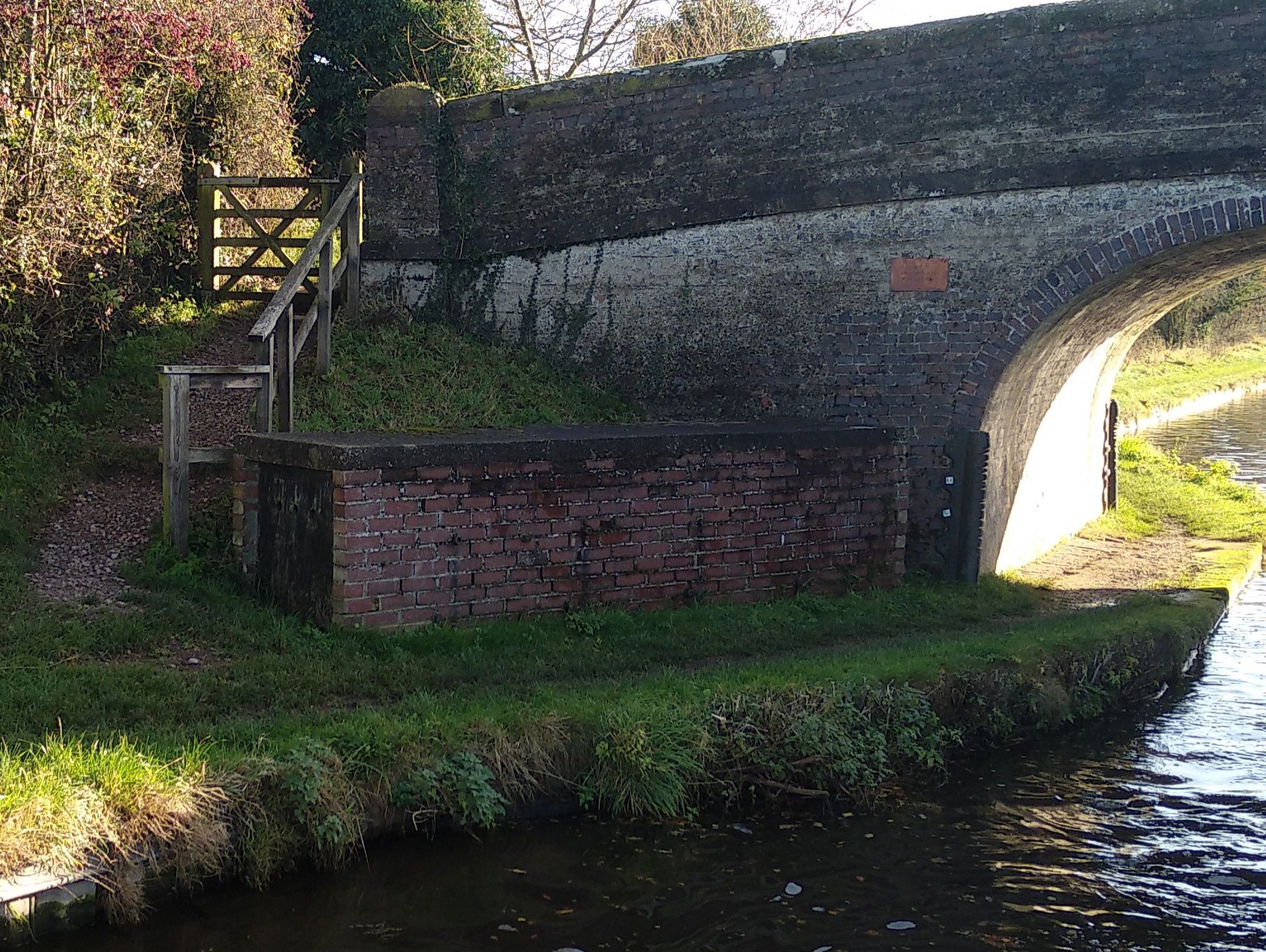
I can't figure it out. Long brick sheds that house mostly litter and long stout planks. Seem to be at almost every bridge on the Shropshire Union. The planks seem long enough to span the bridge hole. My best guess is that they are either to provide a temporary crossing or a platform for bridge maintenance?

-
I'd imagine, being in a tube, that the bow thruster is possibly even more prone to getting clogged with weed or plastic? In that case, how does one clear it? No weed hatch I assume - does that mean you have to take a dip and stick your arm in the tube??
-
I'd be curious to try one some time. I can imagine that they are helpful in reverse judging by my low tech bow thruster (Alice in the bows with a barge pole). But I single hand our 65' boat regularly and reverse quite regularly too. The only times that I really have struggled is in strong winds, and in this case I question whether a bow thruster can easily overcome the winds anyway, since the whole boat tends to move sideways? I can only recall twice that I have seen them used. To move the bow away from the bank when casting off (personally I just push the stern out and reverse, works for me), and going round a sharp bend. Seemed mildly helpful but definitely not necessary. If I was buying a boat I'd certainly be a bit concerned about things going wrong as stated numerous times. I have no right to an opinion but I really can't see the point, and that's honestly not being macho - I don't mind admitting that I'm a pretty mediocre driver. There are a long list of features I'd take over a bow thruster, but perhaps if I tried one I'd love it? Maybe it belongs in the category of "don't try it or you'll know what you're missing!"
-
Just to round this off, I have found a combination of cable length and thickness that gives a consistent output of 50-52A and an alternator temperature of 60 degrees on the casing, 80 degrees if I shine through the grilles. I can also disconnect this cable if I'm about to go on a long cruise or if the ambient temperature is higher than normal (it's around 11 degrees at the moment). I'm calling this good enough for the next couple of months, in the meantime I'm going to try to buy 2 replacement alternators, one to try my hand at field current surgery and one for a spare in case I burn out my current one. I'll contact Beta Marine to find out what specs of alternator I need for my old Beta 38.
-
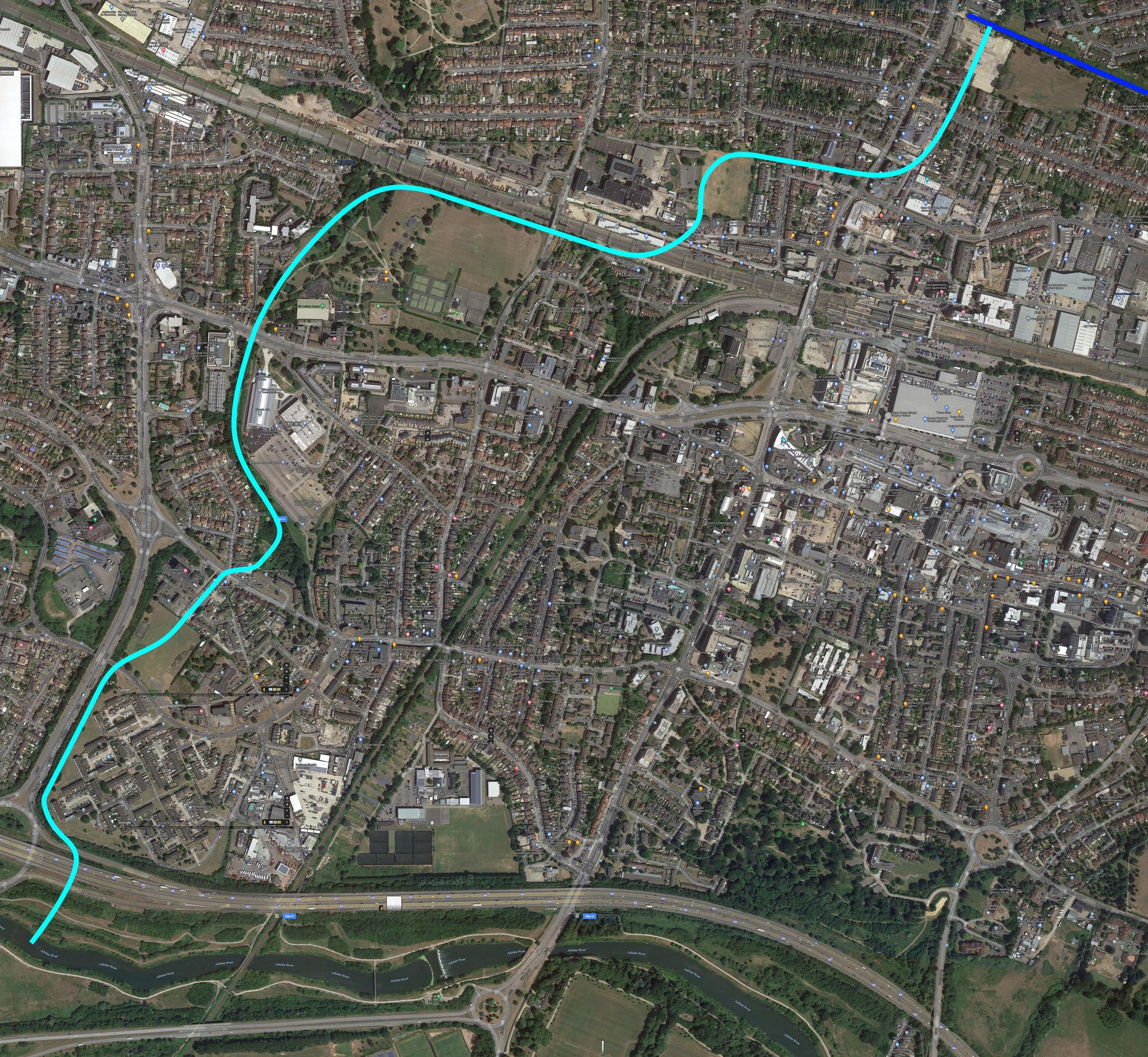
From the linked 2012 article: It suggested the waterway would either go through London Road or the A4 and the M4 motorway, before joining the river at Romney Lock, Eton. Mr Timms said: "It would be a major asset to the waterway system of Slough. It all seems a bit improbable, but there is a lot of money being spent on building waterways in the UK. "It's only one-and-a-half miles long - the problem is the route goes through a built-up area." And @fender in an old thread on the Slough arm suggested the link could join the arm further east: There are many watercourses, the Crane, the Colne, Longford (CCL) etc which may offer some potential with being incorporated into a canal scheme that will allow boaters to enter the Thames nearer Staines/Windsor You're right though there really isn't an obvious way. For fun I tried to plan out how it would be possible. I think it can be done demolishing 6 private houses, 4 larger businesses, 7 road bridges, 2 motorway bridges and a railway bridge. Most of the rest of it goes through parks and recreation grounds. It ends up on the Jubilee river which would have to be made navigable for the last mile and a half. I'd love to know what route thought could be done for 30 million!
-
As nice as it would be to have the entire system to oneself, I'm conscious that the waterways may be a "use it or lose it" situation.
-
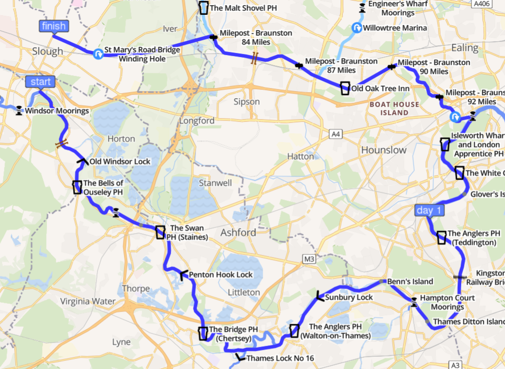
I don't know about that. Of all the waterways projects I've heard of this one seems the most feasible and one of the most useful. It's only a couple of miles and through rather unloved Slough, which could use the development (as per the OP's article). Apparently it was projected to cost 30MGBP in the 90s, which has got to be one of the smaller projects. Certainly a lot more reasonable than the Bedford-Milton Keynes idea. It would bring boats to the much unused Slough arm and with Crossrail in place could even coax London boaters to spread out onto the arm. It would make Slough a lot less of a dump and could bring lots of boaters travelling between the K&A and GU. It would save 42 miles of cruising and 22 locks (not including any locks that would be required to link the two) obviating the need for people coming down the grand union to go into London and onto the lower reaches of the Thames via the Hanwell flight. Of course it's still pie in the sky and of course there is more boring maintenance work that the money is better spent on. But as pies in the skies go it's really rather a mini pork pie hovering around head height...
-
Last year I went to the bottom of the Slough arm and filled up with water from a tap that I had to partially repair. I quite liked the atmosphere, it was gritty! Still, great news that they are developing it, I wonder if they have kept in mind a future possibility to link to the Thames or if this development makes it impossible?
-
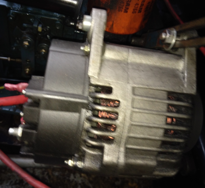
I would have been tempted to leave it for a full hour if it wasn't for the puff of smoke. The alternator is absolutely filthy inside, diesel soot from an old exhaust leak, which probably doesn't help with the cooling and might just be the source of the smoke. Interesting point that it might run hotter at idle. I assumed the opposite so I put it into idle to test it. Yes agreed, I think I may get 2 spares and try surgery on the one at my leisure. With a spare I'm alright with pushing this one a bit and seeing what happens. I wish I knew. It doesn't really have any identifying marks or labels on it. I don't actually know that it is a 70A, in fact now that I've seen it produce around 85A I'm not sure that it could be. Is A127 the name of the form factor? I would like to buy a spare but I'm not sure how to tell what I need nor whether it's right- or left-hand. There are some 75A A127 alternators for sale dirt cheap (50 quid) on eBay - https://www.ebay.co.uk/itm/LUCAS-A127-TYPE-ALTERNATOR-RIGHT-HAND-RH-12V-75AMP/324193342893 I've posted some pics of it before on this forum so here they are again. The belt drives the pulley clockwise if you face the pulley (looking astern). The writing on the regulator reads 07-032 YY13454 14V There's also an embossed number on the casing which is 4135.
-
Added in a length of 25mm cable (so now, this original negative cable plus this extra 25mm one) and ran the engine for about 15mins now. It seemed to bring the current down to 50A at idle, which sounds about ideal! but the outside casing of the alternator got up to 85 degrees and I managed to measure about 110 degrees through the grille which seems worryingly hot. Again, I turned it off aftrer 15 or so mins of running when I noticed faint smoke and a faint burning smell. Also with throttle the alternator was producing 60-65A, so while cruising I'd probably want to disconnect this cable and slow charge. I think the next step is probably to try some fans and ducting to cool the alternator, if I can output 50A consistently I will be more than chuffed with that. What I will also do is try to buy a spare alternator. I'm much more inclined to experiment in the knowledge that I have a backup. If the alternator dies on me out here in the middle of nowhere and in winter with no solar, that will be rather an emergency. And yes the 25mm cable became only just noticeably warm. I'm not sure which of the original cabling was getting warm but somewhere something is, you're right.
-
Attached a 70mm cable from the negative of my Li battery (via my BMV712 shunt) directly to the casing of the alternator. Gave my engine some throttle and started her up. The current climbed quickly from 50A to a maximum of 81.8A (!) and it was running around 3 minutes. So - clearly - the negative connection was the limiting factor with my curent. Nick - I owe you beer. I measured the alternator temperature with my infrared gun, and I could feel the heat almost immediately. The most I saw was 85 degrees, but it's difficult to get a reading on the internals and so it might have been much higher. When I saw a puff of smoke out of the alternator I turned the engine off and terminated the experiment! The alternator is pretty dirty inside, so I think the smoke was probably from some old soot or rubber dust. After disconnecting the thick cable it went back to charging at 30A. So - at least I know that the alternator is putting out decent current if I'll let it, but I'm not really sure what to do now. I can't let it put out 80A because it will melt in ten minutes flat. Perhaps I just need to use an intermediate-sized cable. Or insert a resistor in series? Or perhaps I should create a cooling system, and make sure I have a spare alternator to hand? What we all really need - actually - is the ability to programme our alternators to put out less current. I probably need to stop looking for a shortcut. Wouldn't this be the case if Cells A3 and A4 have slightly lower capacity? That is, they will reach full first and reach empty first? Logging of the individual cell voltages is IMO the most important bit of data to be logged - unfortunately the whole bank doesn't really give you any useful information except at the very top and only if you are sure that your batteries are perfectly balanced. I have started baby steps towards creating an Arduino based monitor for my cells which I want to log every say second or whatever. Right now I'm not even logging the data from my Victron kit though apparently that can be done with Pi running a Victron Venus OS. I think you mean 4 cells not 3 since LiFePO needs 4 cells to produce a 12ish volt battery? I believe Craig said that he uses 4s3p (i.e. 12 cells of 1 unit / 3 batteries rather than 3p4s i.e. 4 cells of 3 units / 1 battery) for two reasons - one pragmatic, because of how the wiring worked out, and the other because he wanted to be able to monitor the health of each individual physical cell unit. That was something I'd considered originally as well for the same reason but I was convinced against it because a) of the complexity and b) because having 3 cell units (4 in my case) in parallel to make a cell is more robust and stronger cell units will protect the weaker ones. I am still not sure if that reasoning was solid, I do love that Craig can identify individual physical cell units that may get sick and need replacing. Eventually what I'd love to get is a CSV file dumped out every week (say) that logs individual cell voltages, cell temperature, alternator temperature, alternator RPM, current, and whatever else I can think of. But unfortunately it's a luxury rather low down on my list of boat jobs to do.
-
The voltage at the alternator is 14.4V, and the voltage from alternator body to Li pos is abour 14.3. So I believe Nick was right and the low amps are almost certainly due to volt drop and almost certainly due to the negative cable being too thin. I am debating whether to upgrade it though, because I think this thin negative cable is the only thing saving my alternator from overheating. I do have 70mm cable so I think I should make up a cable and see what the effect is, watching the alternator temperature and current. I anticipate that I'll see 50A+ and a very hot alternator, but I believe the voltage at the battery should remain around 13.7V while charging because more than that would imply that the battery is full. Will test this setup (and my understanding of electrickery) out tomorrow.
-
I'm not thinking of the regulation but just the fact that a circuit under load will drop the voltage down. Why does a LA battery happily have its voltage raised all the way up to the 14.4V regulation but the Li battery does not? My understanding of electricity is that it's because in the case of the LA, the current is being limited by the battery (the load). In the case of the Li, the current is being limited by the alternator's capacity (the source). So kind of like if you pinch the end of a hosepipe, you'll get less water but it's because the load is not accepting it - the pressure will remain high inside the hosepipe. Whereas, if you turn the tap down, then you'll get less water but it's because the source is not pushing as hard - the pressure in the hosepipe is less. I don't know if that's a fair analogy. But this is the explanation that makes sense to me on why 14.4V on the LA, and then 13.4V as soon as I connect the Li. You're right and I will double check this tomorrow, but I recall it being roughly the same. I might be remembering wrong. Now this is an explanation I can get behind. The negative wires flow through to the engine block and I haven't changed these out. I think they're probably very thin - though they must be sufficient for the starter motor current. I think the bracket/bolts holding the alternator to the engine are also painted and not very conductive? I will try wiring a thick cable directly from the alternator casing to the negative of my Lis tomorrow and see what it does. Thanks kindly for the pointers!
-
Hang on, something doesn't make sense. Why does the alternator output 14.4V to a LA battery but 13.4V to a Li battery? Isn't it simply that Li can take more current than the alternator is giving so it dragged the voltage down, whereas with LA the battery is limiting the current and so the alternator is regulating itself down to 14.4V? In fact, doesn't anything less than 14.4V mean that the alternator is working flat-out? Doesn't this mean then that there must be something else in my system - a bit of thin wire, or component - that is somehow preventing the alternator from running at full strength? Either that or - as Nick suggested - there's something wrong with my alternator?
-
The voltage sits at around 14.4V / 14.5V if it's only connected to my LA. If it's connected to my Li's the voltage sits at around 13.4 - 13.5, slowly rising and if it ever got to 13.8V I shut it off (manually right now - because I don't have an alternator controller - but so far I haven't taken it above 13.7V when charging via alternator - if any one cell got above 3.6V then my emergency BMS should kick in, which implies a battery voltage of 14.4V but in reality is closer to 14.0 since my cells aren't that well balanced). Note that these voltages are taken at the load side of the system, but there isn't that much in it compared to the voltages at the alternator. Ok sure that makes sense. Slower charge will also be better for battery capacity - either way I understand that you'd rather slow down the charge on an 8 hour cruise. Alright you convinced me that the slow charge switch is valuable enough to make the effort! My alternator never gets very hot (most I've ever measured is 50 something degrees). And I've never seen it produce more than 52A or so, but it does produce 50ish A sometimes so I don't think it could be the case that it's broken. I'm not even sure it is a 70A alternator, could be a 60A. So I honestly don't think it's not working.
-
Follow up, the thicker cable does seem to have made a marginal difference, but not by a lot - around 5A or so. So perhaps it really is the field current limiting the voltage of what it thinks is a full LA battery. I'm increasingly reaching the conclusion that an alternator controller like Nick's is really what is required. For now I guess I'm going to be charging at 35A max. Ideally you want to be able to turn off charging when any one of the cells is full, or when the cells are below 5 degrees, or when the alternator is above say 70 degrees. I like his ability to switch between fast/slow charge, but in my view it's only relevant if you have a decent sized alternator - my little 70A (ish) one is never really going to abuse the battery.
-
Practically rather than theoretically though I'm constrained by the realities of living on the boat. We have a 65' boat that goes saloon - galley - bedroom - bathroom - office. The Li's are in the office to be near the alternator, MPPT and all the other stuff. The solid fuel stove is at the bow doors and this supplies the bulk of our heating. When the saloon is warm, the bedroom is comfortable for sleeping, the bathroom is chilly and the office may as well be outside. I'm in the process of reinstalling our Eberspacher based central heating and also a second solid fuel stove in the office and I have a temporary diesel heater set up in the office. Even so though, this is mostly to make it comfortable for me during the workday. If I'm not working then I'd rather not be heating that entire space just for the benefit of my Lithiums. That's the case especially if I'm cruising and charging the battery, but also the case if I'm getting a bit of winter solar power. In any event it seems to make sense to automate a battery warmer so it's something you don't have to think about. I'm going to try the mats connected to a thermostat and a main switch that I can turn off outside of December - March. Thanks for the tip on the mats Craig. If anyone could advise whether this thermostat would be appropriate or could recommend one I'd be grateful. Do you mean to say that you just leave it on all the time? Or that you manually turn it on before charging (say, half an hour before a cruise or sunrise?) The former seems rather a lot of energy to spend on warming the three batteries, if the latter then rather a lot of effort. I get that you have the temperature monitoring but wouldn't a simple thermostat in the heating circuit do the trick for you? Currently my alternator charges my Li's at around 30A constant, and I put this down to the fact that I (intentionally) used a very thin 25mm^2 cable to connect them (to prevent overheating). I noticed yesterday with a flatter than usual battery (around 12.7V) the alternator put out 50A for a short while and I could hear more labouring from the engine. My plan for today was to try out a piece of 70mm^2 cable because at 30A I'm still running my engine too much. Nick, you've made me think - is my alternator not just regulating itself down because it's charging at 13.4V and it "thinks the LA it's connected to is getting close to full?" I think I'll still try the thicker cable, but I have been quite happy that my alternator is happy...
-
Thank you for the suggestion. I think I found what you suggested. It says it is 67W/m and 30cm wide, which should be plenty to put under the whole battery (I presume under is best, on top of a layer of insulation). That suggests it would draw around 6A? Do you use a thermostat with it? There's a cheap board which has a 10A relay - I expect I can wire it on the load side of the BMS and set this to 5 degrees and allow it to heat the battery as and when required. Do you mean to say the cells are blocks of 4 in series x 3 blocks in parallel? When I was first planning my system I intended to do the same, so that I could monitor each of my 16 cells individually. I was convinced against it at the time but the reasoning has become a little less clear over time! I think it was because the series then parallel configuration would allow more opportunity for the cells to unbalance, not to mention a lot more wiring.
-
Since this is a bit of a niche topic I thought I'd continue this thread rather than starting a new one... My BMS is set up to trip the charging relay at low temperature. But a better solution would be to warm the cells up so that they can be charged safely. I've been told to use soil warming cables or vivarium heating pads for this purpose, as they apparently come in 12V versions with thermostats. The reptile ones especially have temperature control in the right range (0 to 35 degrees). The ones I find online are 240V though. I did find plenty of thermostatically controlled car seat warmers which sound ideal, but I expect I need a thermostat that is much cooler - shutting off at 5 degrees or so. I know that keeping them in the cabin goes a long way towards keeping them warm, but the room they're in does get cold if I'm not in it and running the diesel heater, and don't want to rely 100% on that. I would love to hear any suggestions or how anyone else has solved this problem. How's everyone's installs coming? Would love an update @redwing and @nicknorman!
-
‘Unlocking’ the challenge of London’s congested waterways
jetzi replied to Ray T's topic in Waterways News & Press
Can someone clarify exactly what the problem is that we're trying to solve? "Too many boats in London" isn't in itself a problem. Is it that there aren't enough moorings for people visiting from outside the city? Is it that "without a home mooring" licenses aren't contributing enough for the maintenance of the network? Is it that the facilities are strained and aren't adequately meeting the needs of the boaters in the city? Is it that the diesel fumes and stove smoke from the boaters is causing air quality problems? Is it that there is a health and safety risk from having so many boats packed into a small space? e.g. Fire risk? Or is it just a generalised feeling that it isn't fair in some way or that London boaters aren't real boaters? The ideal solution depends on the problem. I've spent a substantial amount of time in London in my time boating and in my view this is entirely a non-issue. Yes the London waterways are congested, but as with many types of congestion I believe it's self-limiting. A number of people above have said they have stopped going into London due to the congestion. Congratulations, you're part of the solution! If there are so many boats in London that it's uncomfortable to be there, then fewer people will be there. The same holds true of roads by the way. Increasing capacity of roads doesn't help congestion, because motorists will find an equilibrium of the convenience of driving themselves vs the inconvenience of traffic. Remember that if you are in the congested zone you are the traffic. I feel some sympathy for people visiting from outside the city for a short time but if you are prepared to settle for your 2nd or 3rd choice of mooring then I don't honestly believe this is a big problem. If this is really what everyone is bothered about, to solve it, I'd suggest making more of the concreted towpath moorable by adding rings (there is miles and miles of potential moorings in London) and making it sharply restricted to 48 hour moorings with no-return within a calendar year. That, or have more bookable moorings. But I doubt that's really what most people here are concerned with. Judging from the comments I've read on this forum for the past couple of years, it's just people who love to hate the city and the boaters in it, because they prefer to boat elsewhere. If you hate boating in London - that's great, you're part of the solution (if we even need one). I replied to the survey with the above opinion. Curious to hear what solutions are proposed, but more importantly I'm curious to hear clarity on why congestion on London's waterways is a problem. -
How many BTUs / watts of rads can a 4.3kW Eberspaecher drive?
jetzi replied to jetzi's topic in Boat Equipment
I don't have a thermostat (that I know of) just a pull switch on/off. Good point. As far as I know the Eber is either on or off. So I suppose driving it hard means simply that I leave it on for extended periods rather than cycling it on and off frequently? Does the Eber not know or care whether it is heating water that is already quite hot? (I.e. from a radiator return that hasn't had enough panelling to cool down the water). I'm not entirely sure how it works nor what is optimum. Previously the eber was connected to a one small towel rail and one large rad. I'm planning on connecting it to three large rads, possibly four. -
How many BTUs / watts of rads can a 4.3kW Eberspaecher drive?
jetzi replied to jetzi's topic in Boat Equipment
I feel it would probable be more effective (and cheaper) to have hotter / fewer rads than lots of warm ones. But more importantly I want to do right by my expensive Eber. -
How many BTUs / watts of rads can a 4.3kW Eberspaecher drive?
jetzi posted a topic in Boat Equipment
I'm reinstalling my Eberspaecher D4WSC Hydronic and replacing the rads. It's marked as 4.3kW. Simple question - how much radiator power can this unit drive? It will also be driving one coil of my calorifier. I've heard it's best to drive diesel heaters hard. Is it as simple as finding 4.3kW of radiators? Is it better to go a little higher?