Mikexx
-
Posts
541 -
Joined
-
Last visited
Content Type
Profiles
Forums
Events
Gallery
Blogs
Store
Everything posted by Mikexx
-
I see the idea, I will think about this a bit more. I've no idea how long the stub is, but the idea of having a tube former the hole drill can sit over sounds a good idea of centring a hole-saw. I think some measuring if the actual pipe size is in order. I suspect it's either 1.25" or 1.5" BSP pipe.
-
I was reticent of moving the exhaust exit, this argument has me convinced!
-
I'll attack the hull around the exhaust pipe with an angle grinder at the weekend and report what I see. Access to the rear-most part, through the depth of the diesel tank, is very poor. I don't see any alternative to the downhill run. To be honest the exhaust is quite high up on the hull, and only just below the rear deck floor level, so the risk of water ingress is quite low.. That is a plan. However if threads need cleaning up or remaking in situ there isn't going to be enough room. I've never been successful with heat with iron on iron. I'm not sure how I can successfully use a hole saw on a pipe. It has got me thinking but I am wondering if a jig-saw or other reciprocating saw might be a way forward. Thanks for all the ideas.
-
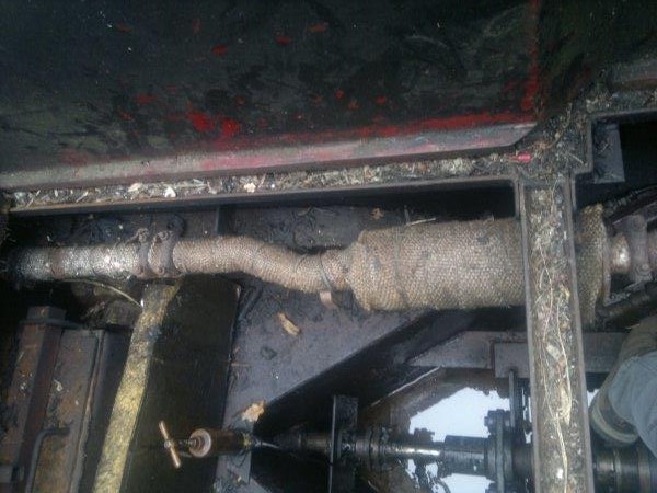
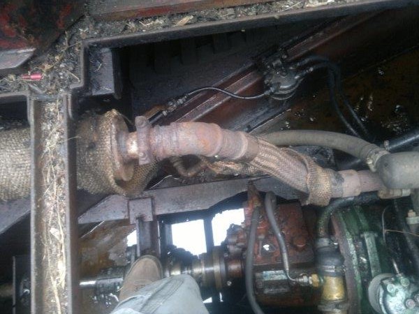
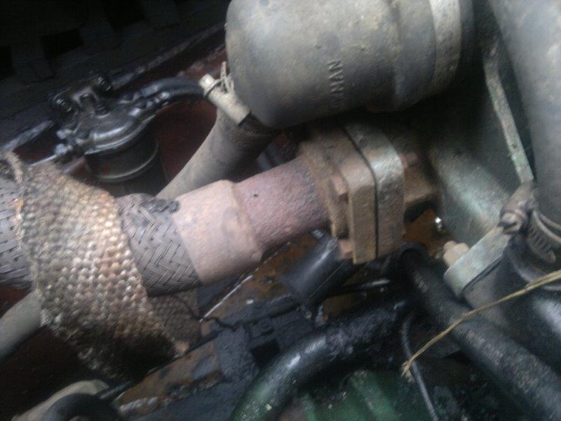
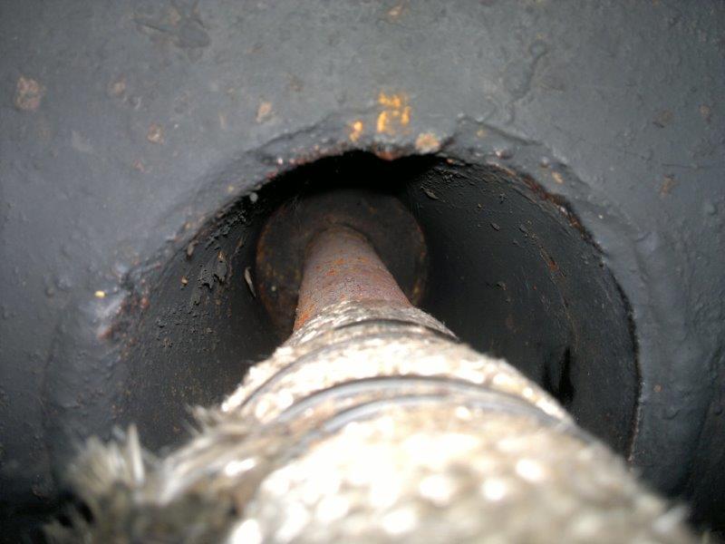
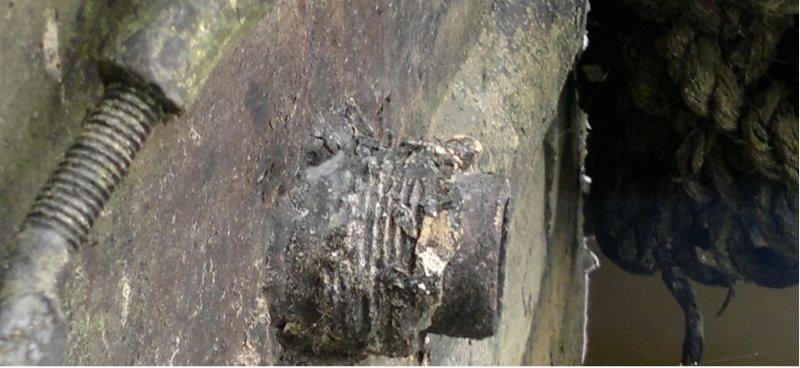
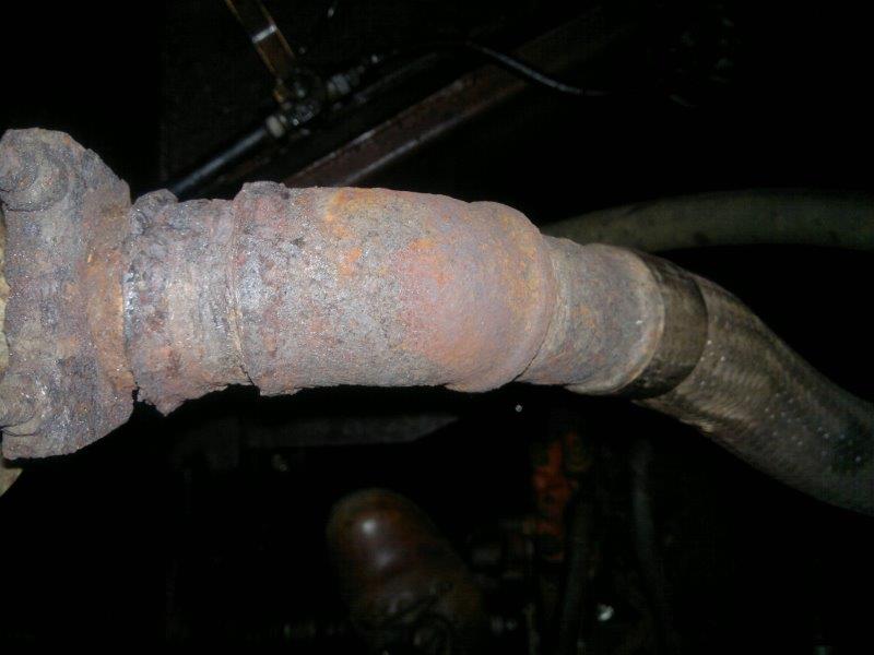
The short pipe between the flange on the Bowman and flexible is seriously holed. The whole of the exhaust is currently suspended from the rear. Although there are a couple of brackets connected to the Swim, they aren't actually used. I would like to undo the exhaust, though it is of sufficient age that I am happy to remove and replace the lot. I do have access to pipe threading vice and dies so tailoring to fit shouldn't be a big issue. I have been able to make one thing move using Stilsons, the 45 angle fitting (in the last photo). However I suspect if I apply any further force it will fall apart. Photo 4 is perhaps the most telling, it is where it passes through/past the fuel tank. Photo 5 is where the pipe emerges. The gunk appears to be mastic, but I can't see any fitting I can remove. Is this setup standard? Any ideas on how to proceed to remove the exhaust attached around the fuel tank?

-
Removing old bitumen when blacking
Mikexx replied to tomwillans's topic in Boat Building & Maintenance
What happened to the Roto Stripper? http://www.ebay.co.uk/itm/Roto-Stripper-Paint-Rust-Remover-Drill-Attachment-New-Redesigned-Multi-for-/271523014547 Not that I have ever used one. -
Removing old bitumen when blacking
Mikexx replied to tomwillans's topic in Boat Building & Maintenance
It looks painfully slow. -
I don't see any reason why you can't connect a short wire to the Starter +ve lead. That is how mine is wired and in common for cars. It saves a lot of faffing about. The alternator cable size is more dependent on charge current and length. I don't have a feel of what voltage drop is acceptable for an alternator. Thicker, of course, is better as is shorter.
-
Just looked up and the A127 is indeed a Delta stator so can be converted. Most alternators I have come across have been star, and on rare occasions have another pair of diodes connected to the star point. I'm left wondering how compatible a 24V alternator is and whether a 12V regulator could be fitted for super low cut-in?
-
The alternator looks as if it is a Lucas style which would I would expect to already have a stator in a star 'Y' for max voltage. If it's currently a delta winding then yes I can see how you can improve voltage output when changed to a star. The rotor would normally be close to, or in, saturation so any increase in magnetic flux from an increase in magnetic field (NI) would be minimal. What sort of reconfiguring did you have in mind?
-
The readings don't really add up, literally. I could also assume the battery at 14.37, just 0.13V less than the alternator is also correct. One thing about cheap DVMs is they are sometimes upset by an AC waveform on top of a DC waveform such that I might not trust 100% the direct alternator measurement. I can't quite make out the DVM name in one of the pictures, either way it doesn't look familiar. In the very first photo in this topic, the alternator power cable has a section covered with insulating tape. One wonders what's below that! The 0.7V is worryingly high, but the 0.15V is the wrong polarity. Are you suggesting the original fault could have been caused by a failure of an unknown parallel resistor? I suppose coincidences do happen! I'm not sure if we have moved forward, apart from ascertaining the battery seems to be charged sufficiently, and the exciter switch is doing its job. Without applying a serious load to the battery whilst the alternator is producing an output I can't see us moving forward. There isn't a second alternator on the engine so I'm also wondering what Roxylass does for power?
-
I understand the sentiment, but a gear specialist will want to know the distance between the two shafts, the number of teeth on each gear, the width of the gears and the nominal helical angle. Providing the originals will raise confidence but even if one was seriously damaged, I can't see how a drilling that would be an issue. You may be able to find some off the shelf gears which can be machined to the correct width and fit your shaft diameters. http://hpcgears.com/n/products/13.helical_gears/helical_gears.php
-
No need to apologise. With meter on DC20: 1 Place black probe on battery -ve terminal, red probe on the alternator metal casing 2 Place black probe on battery +ve terminal, red probe on the alternator output stud (heavy red wire) 3 Place black probe on alternator body and red read on alternator output stud (heavy red wire) 4 Place black probe on batter -ve terminal, red probe on battery +ve terminal. I know you have made some of these measurements before, but if these can be made quickly one after the other it would place more value on the other measurements. Can you also note if you get a negative reading, you should on (1)?
-
Brill, that suggests the alternator is working as expected. You mentioned a previous battery voltage was was measure at 13.60, was this on the AC setting? When running, now measure between the alternator body and the battery -ve and report what voltage you get? Also when running measure between the alternator output and the battery +ve. If both of these measurements are near 0v and both alternator and battery volts are around 14.5V, apart from the exciter switch all seems to be working fine and your starter battery is being topped up after a start. Personally I would then leave all alone.
-
I have no idea what access is like. 1 Bigger puller 2 chain drill along a tooth valley, cold chisel and remove 3 drill into the side of the gear and pull (harder) 4 angle grinder to remove one side of the gear close to, or down to shaft 2 and 3 will only work if the gear hasn't been tempered, but given the state of the gears, any temper they had must be long gone! Heat is more likely to work if dissimilar materials. It can work but also seen what was a cold-weld just get worse. Good luck!
-
I'm not sure if much is gained by this?? What might be more relevant is the difference between the warning light terminal and the alternator output terminal. That might indicate if a diode is U/S. In spite of the earlier measurements being made on an AC setting, it does indicate all is well, at least somewhere. Its also not clear where the black and red multimeter leads were making contact and what was being measured.
-
The fat wire leading from the alternator is the one of interest. There should be a terminal at the alternator with a approx a10mm nut on a stud. Can you measure the voltage here? And with the black voltmeter wire on the alternator body? It goes without saying, make sure your fingers stay away from the belt. I'm now wondering with your refurbished starter if this is an isolated starter and you've lost an earth somewhere.
-
Except Roxylass said "The battery shows 13 volts before starting" and "Engine running not even half throttle it's showing 13-50 13-60" That possibly implies the battery wasn't flat but equally wasn't taking a charge. I agree we might get a more accurate picture knowing the battery voltage after 1/4 or 1/2 hour or so of running. I would still like to know the terminal voltage at the alternator!
-
Most fitters would observe the corresponding lower voltage output and recommend a new alternator. I bought one recently on eBay for less that £50 for 75A lookalike, such I wasn't going to start investigating my problems any further although brushes are just a few ££. If Roxylass confirms that the output at the alternator sits at 13.6V when running, whilst all else looks good then it does point to a diode. By the time an expert dismantles it and changed the diode pack it would cost more than a new alternator.
-
Thanks, I'm not proposing full throttle, just set in a position to provide what could be described as high cruising revs. The fact the light stays out, and presumably only comes on when the engine is topped, implies the alternator is working fine. Can you measure the voltage at the alternator terminal when running and report back? It is possible that the wiring between the alternator and battery is suspect.
-
I would like to see above 14 volts a short time after starting. Most alternators don't charge below 2,000 rpm, do the volts increase at higher rpm? If you switch the exciter switch off does the lamp come back on?
-
Another bulb or resistor in parallel with the original lamp can be used if a higher wattage bulb of the same style can't be found to fit the existing lamp holder.
-
Are we talking of 'both directions' as in forward or reverse? I would hope there might be a whole lot more forward than reverse!
-
I've never seen gears like that before. Its as if corrosion, cavitation or some other random metal removal has taken place such as getting extremely hot and hot welding has taken place. What is most surprising is the surface is the same both sides of each gear. I would expect the wear side surface to be far worse than the non-wear side.
-
I would like to know the thread details before passing judgement. 65 ftlbs does seem high, I also concur with the values quoted for the BMC but I suspect they are smaller bolts? I am left wondering if the bolts have stretched though temperature cycling and use and were found in the 25ft-lb position. Perhaps new ones might line up better? I've never seen wired big end bolts and all b/e bolts I've come across normally stay in place through stiction. If you want positive retainment for the existing studs feel there are two choices, one to tighten a part turn further for holes to line up, another to use thread-lock. There are many instances where bolts are intentional placed into their 'plastic' limit where the last tightening is through some fraction of a turn. They are then marked as they can only be used a finite number of times, or simply discarded for new.
-
I second that. I would place emery cloth or other fine abrasive paper on something very flat like glass and rub the nut along the paper. The only issue is that abrasive material may be carried on the nut and so need a good clean before reassembly.