chris collins
-
Posts
52 -
Joined
-
Last visited
Content Type
Profiles
Forums
Events
Gallery
Blogs
Store
Everything posted by chris collins
-
I've been trying to get some time to put the last couple of planks in since Christmas and it has finally happened. Time for a bit of celebration. Just leaves, the shearing, iron frames, stern wooden frames, engine beds, fore end deck beams, compass pieces lower breasthook, deck, breasthook, cants, coaming, winch, bollards, hatch, side decks, coamings, hatch boards, stern deck bearers, stern deck, coaming, sterngear, rudder, steering gear, diesel tanks, engine, water cooling pipes/mudbox, cabin, miscellaneous navigation lights, rubbing bands, stem iron and anything else that I have forgotten. Not holding my breathe.

-
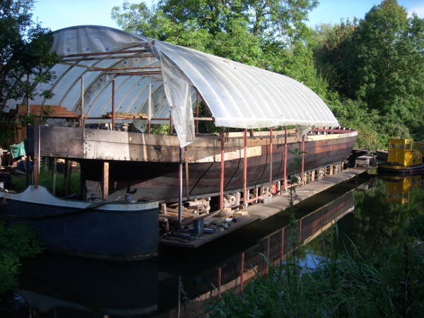
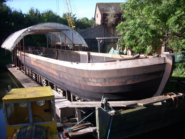
A long ,long time since the last post so you'll be expecting something nearing completion..............unfortunately the spring and early summer disappeared clearing the backlog of jobs that had built up, docking my own boat. I guess the clue to that one is in the name. SPA50129 by chriscollins1, on Flickr Maintenance on “Mimas” and the other Troy wharf craft, maintenance of the Troy arm itself etc, etc. SPA50135 by chriscollins1, on Flickr SPA50137 by chriscollins1, on Flickr One high point was a visit from Tam & Di, great to get a bit of background on their time of ownership, I hope they have a bit more time next visit. The first narrowboat that I rebuilt took 18 months and each successive one has taken longer, I'll claim that the quality is much better but truth be told I'm older and slower as well. It's also the case “that the more you learn - the more there is to learn ” all of which takes time. Anyway it seems as though it's taken 18 months to working around the counter area, (It hasn't but it certainly feels like it ) . Good job G.U.C.C aren't waiting for the launch. It has certainly been “interesting” just how much bigger and heavier the component parts of “Progress” have been, bit's that would be about the limit of my strength on a normal narrowboat are the source of double and triple curses, hat's off to Bushell bros for the first build. SPA50190 by chriscollins1, on Flickr SPA50191 by chriscollins1, on Flickr Earlier in the thread Lawrence kindly forwarded a set of blueprints for a steel version of “Progress” and I am pretty sure that the intention was to build the proposed fleet of wide boats in steel, I am also pretty sure that the lines/shape for the wooden “Progress” where taken directly from the “steel” drawings. It is around the stern area that the quirks and foibles of this approach really becomes apparent. It's a lovely shape but you can't help but think that Bushell's would have felt a little compromised by some of the construction details needed to achieve said shape. SPA50217 by chriscollins1, on Flickr SPA50214 by chriscollins1, on Flickr It's fair to say that given a few more “Progresses” to build Bushell would have developed the plank shapes around the stern for easier fitting, at the moment some are such that they can't be positioned until they have been bent, but, they can't be bent until they are twisted, and , you guessed, they can't be twisted until they have been positioned. Hence the clamp fest and a lot of fiddly farting about, (that farting bit could just be an age thing). SPA50216 by chriscollins1, on Flickr So, the planks are still not fastened to the frames, I will need at some stage to use a few temporary fasteners as the planking gets higher. For now I'll admit to being quite pleased at the way that the planks are holding their shape, people quite often ask “how much bend will a steamed plank retain if unfastened?” and this photo gives a clue, not scientific but a bit of fun. SPA50078 by chriscollins1, on Flickr
-
Hi Laurence, this definitely is not on the river chess nor has it been anytime in the last 30 years, unfortunately I can't offer any help as to where it may be. I'm sure that someone of greater knowledge will be able too identify the area.
-
1931, an “average” saloon car retails around £300, a Bentley ( chassis only) around £2000, makes a pair of boats at £1050 sound like a bargain. 2014, £63,924.98, well, it would cover the materials.............. Tim, in the past I have tried spiling to the outside lines, of the two I find spiling to the inside to give a better fit on the mating surfaces, but for sure I can't build a pair of boats for £63,924.98, so, as they say...you pays your money.....
-
A little bit bit off track but hopefully of interest, A long time ago Tony Walker (Walker Bros) gave me a copy of this tender originally submitted to Associated Canal Carriers. I'm sure that he would have passed copies on to other people over the years and I'm equally sure that he would have put it in the public domain had the internet been available. It's possible that one of the nice knowledgeable people on the forum might tidy it up a bit and make it more legible.
-
Spiling part 2. At this point we need to “take” the bevels, start by making station marks, I normally mark every twelve inches, number the stations. At each station take the angle that the back of the proposed plank will meet the top of the plank below with. It's worth taking the time to get this right as it helps massively in getting the plank to sit correctly once bent. Now find a strip of wood as wide as your plank is thick and transfer this angle across the face, number the mark to match the station and so on through the length of the proposed plank, as you work along the straight section the bevel should remain constant. Back to our board, normally you can be certain that the board you need will be at the bottom of the pile. So, having found a board that we can avoid any faults on we can start to transfer our marks. Either with the appropriate spiling block....... Or by ruler ….. A nail at each point acts as a register to form a batten around ready for marking. Once the inside line is marked we'll need to mark our station marks for the bevels. On the majority of narrowboat planks the outer side of the plank will be the widest so we'll need to add enough material to allow us to cut the bevel. We can mark our 12 inch stations along the proposed lower edge line and refer to our bevel board to get the amount to be added at each station once again using a batten to join the dots for marking. If all goes well we'll have laid the foundations for a good tight fitting joint(s). So, hopefully that's clarified the process, happy spiling.
-
Spiling part 1 In a (much) earlier post I did try to describe the process of “spiling” to get an accurate template for a plank, I'm hoping that you won't mind if I revisit the subject in order to try and clarify it a bit. It's a bit image heavy so I'll have to post it in two parts, hopefully it will be helpful to someone. The mythical, magical spiling board is not quite as exotic as it sounds, just a board that you can clamp to the boat and make notations on. It helps if it is thin enough to be reasonably flexible, wide enough to support itself along it's length fairly well and free from large knots or other faults that may influence the fairness of any bend that you may put in it. Normally the shape of the fore end will require more than one board to be joined to get around the sny in the plank, on “Progress” this has been required for the stern as well. This board is on it's third rebuilding job, it's about 20 foot long, six inches wide and around half inch thick. Occasionally the original frames can be used to support the spiling board but it is worth having a long hard look at what the original builder had intended and whether those frames are still an accurate representation of that intent, very often age and a hard life have taken their toll. On this side of the fore end of “Progress” the decision was made simple when the port quarter collapsed in a pile of mushroom compost interspersed with bits of plank and frame, luckily the starboard side has stayed relatively intact to act as a pattern. So, first job is to put up some temporary frames to support the spiling board. The line of the frames, shape and depth of the hoodings and the top edge of the plank can be checked by hanging battens as needed, the top edge of the plank is worth checking carefully as it's quite possible that this may have been influenced by the the timber available at the time of the original build, you've then got the choice of following the original intent or the original result, you will of course be damned if you do and damned if you don't but at least you'll be making a decision based on knowledge. When you are happy that all is fair and accurate you can hang the board, as can be seen here the shape of the proposed plank precludes the use of a straight spiling board for the full length, at the far end the “straight” board will be rising again to the boundary of the top edge of the plank . At this point I'm still about 8ft away from the stempost and will need to join more pieces on in order to achieve the shape. It is vitally important that the spiling board sits snug to it's supports, particularly around the fore and aft curves as any discrepancy is magnified by the increased effective radius multiplied by Pi. The worst case scenario is where the lower edge of the plank is snug but the top edge is angled slightly outwards, the resulting plank will carry a disproportional amount of material along it's top edge. The extra material will not only affect the stretching and compression stresses when we start to bend the plank but also it's shape lengthways as any attempt to clamp in the resulting bulge will want to push the ends of the plank in a downward direction. If the plank is the right shape it will usually “allow” us to make the bend and although it won't exactly “fall” into shape it's noticeable that it will pull round and hold it's shape with a bare minimum of clamps. The blocks are where I have started to join on more pieces to follow the shape along and round to the stempost. So board(s) in place, time to start marking, choose your weapon...... Simple, efficient and proven over many years, if there is sufficient space around the spiling board then purpose made spiling blocks work really well. Mark your line along the full width of the top of the block to aid alignment when transposing your marks. One of the advantages of using spiling blocks is that you can mark both sides of the spiling board relatively easily, this can be very useful later when you are sorting through the timber pile as it often saves having to turn over the flitch to see if your proposed plank will fit. Normally a “set” of blocks is required to cover for the varying distance 'tween board and plank edge. Just remember to mark which block was used where! As all you are doing is making repeatable marks on the spiling board there are other methods, a simple consistent measurement such as this backed up with a line along the edge of the rule to aid alignment works fine, people working on smaller boats often use compasses. All marks are taken from the inside edge of the plank as this is the most important side for us to get right, often the outer side is the larger due to the plank bevel but it is still more accurate to mark the inside first and use it as a datum to then mark the outer. When you are sure that you have got all the marks you need (plus a few for luck) carefully take the spiling board down, I like to use a template at the hood end for a bit of added reassurance. Lots of care handling the board over to the timber pile helps preserve the accuracy.
-
Speedwheel, that's brilliant, I've spent the last 25 years looking at pictures of “Progress” and I've never come across this one before. It looks very early on as it still has the hatch covers and life rings, the kind of things that could get misplaced or damaged. It also doesn't appear to show any loaded tide mark (could just be the photo?) Tam / Di I'm hoping that one day when your over this direction you'll drop in and have a look over, maybe give us a call beforehand as the yard gate is normally locked. I've just been reading the post about “Mossdale” and it's really nice to see that moves are afoot to prolong it's preservation, lots and lots of goodwill and goodluck to all involved. Reading through the post there are a couple of “general wooden boat preservation” points that could be worth a thought. With regard to the criticism levelled at the museum it's worth bearing in mind that working boats underwent a long period of development to suit the purpose for which they where built and the change of use to “static exhibit” is very much at odds with that evolution. The deterioration of an ex working vessel is accelerated in many subtle ways just by standing still, some,such as the constant waterline and sunny / shaded sides are obvious, others take time to manifest themselves. It's worth considering the role of free air movement as an example, whilst a boat is being used there would be an almost constant flow of air over, round and through the vessel, from the movement of the boat itself, the people moving within, open doors / hatches, a lighted stove, the list could go on, all contribute to moving the layer of saturated air close to any damp surface (inside or out) of the vessel and replacing it with drier air in a constant and beneficial cycle. (A useful analogy here is how much quicker your washing dries when there is a breeze to move the saturated air layer close to the surface, far more effective than temperature alone). Our static exhibit may well be shut up for weeks on end, clothed up to keep the rain out and in the process excluding any beneficial breeze available. The average air humidity level in this country is around 60% , at 90% air humidity wood becomes sufficiently wet to promote and support the brown rot organisms, clearly the inevitable condensation (100%humidity) cycle within a closed cabin or hold area is far greater on our “static exhibit”and hugely increases the risk of the growth of spoilage organisms. With such things in mind it's pretty clear that if boatbuilders had been developing a “static exhibit” over the last few hundred years we would now be looking at a completely different shape and construction. As things stand there is a very real possibility that a newly rebuilt “Progress” or suchlike could have a considerably shorter lifespan as a “static exhibit” or “occasionally used recreational vehicle” than in it's original life. At the present time the “craft” of “looking after” our small and dwindling stock of vessels is a long way below the “critical mass” of experiences, solutions and communications needed to build a solid and sound protocol for long term preservation, the small number of vessels involved, the (comparatively) short term involvement of the people exposed to the experiences and the geographically fragmented nature of those experiences hinder the validation and potential enlightenment concealed therein. So, as you'll probably of guessed, I have a certain amount of sympathy for anybody that tries to prolong the life of a wooden ex working boat.
-
Pluto, that's fantastic, I'm full of questions about the when / where /who of the builds, the origins of the regional differences, so first off I'll send you a message about your article, many thanks.
-
Pluto, thanks for sharing that, the photo illustrates the shape very well, the planking seems to be about halfway between traditional canal style widths and “normal” maritime practice. I've never really had an opportunity to study the wooden L&L boats so any other photos/ info you can share, and in particular construction details would be well appreciated. Pen n ink, I've never built a curved staircase ( or any other staircase) so lets stand together and raise a glass to the gods of trees, wood, tools and skills, long may it last. Derek, As you allude to, the development of skills is linked to demand, and unfortunately wooden boatbuilding is in pretty low demand right now. In the wider scheme of things, although we have built machines that require minimum of human input to efficiently produce high quality “articles” for our consumption, and it cannot be denied that the material lives of all of us have been enriched by such manufacturing, one of the hidden costs is the loss of handcraft skills. It is difficult to see many youngsters being able to finance the 10,000 or so hours that turns a talent into a skill that, frankly, will pay a good deal less than the same time invested in a white collar job. So unfortunately it looks increasingly likely that, just as we now have children that don't realise that chips are made from potatoes, we could have a generation of children that have never witnessed anything being made. Hey ho, it's not really that long ago that being a knight in shining armour would have been a great skill to have, not a lot of use on the M25 now, time moves on regardless.
-
This is a gorgeous shot of “Progress” in build, I wish I had a better copy of it as it does not really do justice to the shape of the swim/counter bottoms (to be fair none of the photographs that I have taken show the shape particularly well either, possibly to do with the way it reflects the light? I have to admit that it is also bit of an ego boosting shot in a “Wow it looks really huge”sort of way, hopefully that boatbuilder is more than 3' 6'' tall. Unlike a “normal” motor narrow boat where the counter bottoms sit atop of the swim planks and stern post at near 90 degrees (albeit with a nicely constructed concave underside) on “Progress” there is a rather more organic radius between the two components. Naturally a lot of the original has rotted badly which makes the details of the method of construction a bit more of a detective job, however one of the advantages of working around the swim area is that as it tends to be relatively unworn it will sometimes reveal details that would be lost in the more vulnerable areas. Just a couple of shots to show that I'm not very good at illustrating the shape of the stern, perhaps not all pictures are worth a thousand words? Although the bends on “Progress” are no more severe than on your “average” narrowboat in order to achieve the shape there is an enormous amount of twist in the lower three strakes. It is interesting that in the majority of sea going vessels similar shapes would have been fashioned with much narrower planks. Whilst a more detailed examination of the two approaches is beyond the scope of these posts it's a rich source of food for thought. “Progress” is very very close to the limit of what can be done with 2” oak and it's intriguing to to take peek at some of the methods employed to get those curves. When I first looked at these frames I thought that the curve across the board had probably been shaped after the plank had been steamed into position, possibly using temporary frames first to form the bend/twist and then fairing the convex inner face before fitting the permanent frames. Using the natural tendency for timber shrink more in its inner face when cut tangentially could help develop the curve but the amount of “cupping” needed would exceed what is available naturally. Unfortunately steaming the plank will not help either as the bond between the cell walls across the grain is not strong enough to allow us to stretch the convex radius. When we bend timber,along the length of the grain, cold or steamed, we will stretch the fibres on the outside of the radius and compress those on the inside, unsurprisingly the outside seems to stretch a bit easier than the inner compresses. When I first started I was quite surprised when I carefully templated the inside lines for a plank, equally carefully cut and finished said plank, steamed it and found it had grown to be 3/16” too long. Similarly when we twist a plank it will stretch or compress along the fibres of the grain, what we cannot do is introduce a bend across the grain which is, unfortunately, what we would need to do to avoid having to fair that inner face. So, I was expecting at least a part of the convex shape to have been cut after bending........... However as this shot of the hood end of the plank shows, the shape has been cut all the way to it's mating face to the sternpost so it was probably shaped before steaming/bending. Allowing for a bit of age deterioration this would have been around 1 1/2” thick when new. Going back to the “in build” picture at bushell's it's interesting to see how high ( or low) the original stood during build, as can be seen here the shape of the plank and it's initial angle to meet the stem or stern post dictates more than the normal amount of clearance under the vessel. So far all of planks, stem or stern, have involved a certain amount of plank to dock interface, usually accompanied by some fairly frantic scrabbling to get the plank up and around before the plank cools off. Oh to be a Fly on the wall at bushell's ?
-
Hi I used to be able to use flickr as a host, cut and paste the bb code on to a cwdf post with no problems at all, as with a lot of things computerwise flickr updated, cwdf updated, I didn't, now I don't get the choice of a bb code, just a link address which cwdf rejects with You are not allowed to use that image extension on this community..
-
Hi Ray, you have probably chosen the worst person to ask about dates, I'm pretty useless with names, dates and all manner of other useful information. Although I have rough idea of the order of things in my mind it's certainly not to be trusted enough to put in black and white, to quote Mark Twain “when I was young I could remember things whether they happened or not” I can remember Mrs Best saying that she wasn't all that keen on “Mimas” because the gearbox kept breaking down ! Obviously if it's important to you I can have deeper look “in the archives”and have word with John or put you in touch with him, although I think he was just a toddler at the time. On a more general note there was a good article in W.W about 25 years ago about the Ovaltine fleet, If you haven't seen it let me know and I'll try and scan it and let you have a copy.
-
Super, I'll give it a try and hopefully here's that last couple of pictures. More of the same really, reminds me of what lovely summer we had. That's probably my image allowance done for this time, I'll try to get some more captions done soon to get a bit more up to date.
-
many thanks
-
Well that didn't work!! I'll try to work out how to post the images with the new flickr set up,
-
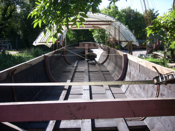
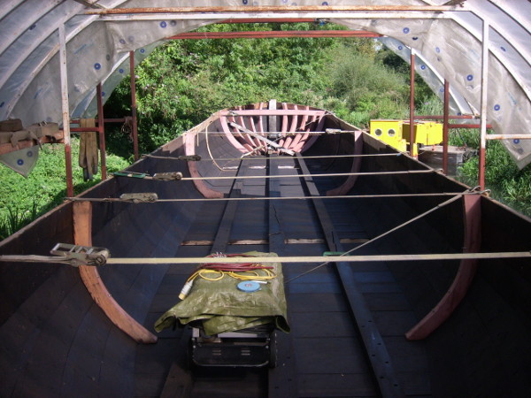
A long time since the last post so it would be reasonable to expect to see lots of new bits, however a plethora of other time consumers have conspired to slow things from merely just “very slow progress” to “almost non-existent progress”. “Mimas” was due a docking and as “Progress” is obstinately filling our dock a spot was booked with Jem to use the dock at Bulbourne. We where lucky enough to have John Best (son of former “Mimas” captain Alf Best) steering for the journey to and from the dock, a pleasure and education for us and a pleasure and (probably) exasperation for John. From a boatbuilders point of view a journey like this with an with an experienced steerer (John had his first boat, a single motor aged 14) is great opportunity to watch the interaction between the boat, the boatman and the canal. http://www.flickr.com/photos/chriscollinsboatbuilding/10317436414/# The docking itself went well, just hardening up the caulking and blacking. The paintwork is standing up well, the cabin roof suffered a bit last year so we have repainted that but for the most part the rest is looking strong after four years, long may it last. http://www.flickr.com/photos/chriscollinsboatbuilding/10317482246/in/photostream/# In the midships of “Progress” there are a pair of wooden frames and it seemed like a good time to replace these as although I shall not fasten the planking to them permanently at the moment they will provide a useful and solid temporary fastening/ clamping/ reference point. http://www.flickr.com/photos/chriscollinsboatbuilding/10317647524/# This old bandsaw is the same age as me, it is in better condition, has less bits missing and will doubtless outlast me. It also makes a very good job of the inner curve of such frames, the biggest problem is getting the timber onto the table and moving it smoothly, waxing the table - candle, kids crayon or furniture wax, any type seems to help for the latter. The bandsaw was part of a parcel of machinery that I bought from an old quarry in Devon many years ago. Although machinery like this is useful the “usefullness” is more by way of increasing the quality of work, lovely as the old hand tools are there is a point when the energy levels start to lag and that (seemingly) tireless national grid is more prepared to go the extra mile. http://www.flickr.com/photos/chriscollinsboatbuilding/10318028463/in/photostream/# As the frames are a pair it makes sense to work the outside shape together to ensure that they stay identical. The shape of the planking lands is drawn from the original pair, usually one will provide any information missing or distorted on the other. http://www.flickr.com/photos/chriscollinsboatbuilding/10317848614/in/photostream/# Although in the photos “Progress” looks fairly straight in the top three planks this shot gives an idea of how much shape there is in the hull, I'm really looking forward to seeing it as it should be. http://www.flickr.com/photos/chriscollinsboatbuilding/10318028463/in/photostream/ I was hoping that the stern planks would have a bit less “sny” (edgeways curve to you and me) , unfortunately I was wrong so I'm still only getting one plank out of some really nice boards that would normally provide two. The sny is a product of the barrel sided nature of the boat, most narrow boats have a certain amount - “Progress” is, as ever, just a little more extreme. http://www.flickr.com/photos/chriscollinsboatbuilding/10317647524/in/photostream/ The frames at the stern have been beautifully preserved by the oily bilge water at their lower ends – unfortunately they are rank rotten at what was the waterline. More of the same really, reminds me of what lovely summer we had. That's probably my image allowance done for this time, I'll try to get some more captions done soon to get a bit more up to date. http://www.flickr.com/photos/chriscollinsboatbuilding/10317877406/in/photostream/ http://www.flickr.com/photos/chriscollinsboatbuilding/10318028463/in/photostream/
-
Message from Mrs Collins, STOP IT ! We where supposed to be going to the cinema last night – got thrown out after five minutes as the people behind could not see past his head! It's really nice to be on the receiving end of such accolades but to be fair they would be far more accurately directed at the art and craft of wooden boatbuilding, in this instance all I am really doing is copying what is already there to the best of my ability and with the benefit of hindsight. The quality, fitness for purpose and aesthetic that pleases us so much has far more to do with the accumulated knowledge and skills of the generations of craftsmen boatbuilders that preceded me. That it was all done in a far more commercial environment and all done without the benefit of modern equipment really puts me in the shade! Having said that, if this thread generates enthusiasm for and understanding of wooden boats and wooden boatbuilding then I'd be more than happy, if it helps someone with their own restoration,kick starts a project or garners a little support for your “local” wooden boat project then I'd be more than, more than, more than, more than happy! To put things into perspective for bee, since I started “Progress” I haven't put up any shelves (straight or wonky) at all so you are ahead of me there. So, please bear in mind that I'm still looking for information (photographic and anecdotal) about “Progress”. There is a distinct lack of info on the period between 1935 and 1958, over 20 years of the prime of it's life, what was it doing? Surely there must be some photographs of that period? Even if it's just sneaking in the background somewhere it would help.
-
All kelsons in place. SPA50130 by chriscollins1, on Flickr And the view from underneath. Wont be so chirpy at caulking time will I? SPA50113 by chriscollins1, on Flickr This is a lovely picture of “Progress” in the build with lots of points to note, in particular it shows the unusual curved transition between the swim planks and the counter bottom, should make things interesting! I didn't notice the height of the sternpost at first, when I did I just assumed that it was cut off later in the build as per narrowboat practice – no – it really is that tall and finishes just under the deck. SCAN0004 by chriscollins1, on Flickr The two big rusty looking nuts above and below the stern tube are attached to a couple of of bolts just over thirty inches long that go through the deadwood and through the sternpost, the sternpost is too big to extract with the deadwood so they and the stertube need to come out. SPA50114 by chriscollins1, on Flickr Although those bolts where a battle to get out they where a comparative doddle compared to the sterntube, I've never had much trouble with the other boats I've worked on but this certainly made up for having an easy life in the past. The bearing was seized into the tube, so, cobble together a puller – zilch- cut away the sternpost and apply a bit of heat – zilch – hours of hot/ cold cycles eventually saw it out, naturally the flange was seized to the tube and the tube was seized in the post/deadwood . SPA50134 by chriscollins1, on Flickr I was quite keen to maintain the integrity of the hood ends of the planks for the moment so the fastenings where extracted with a bit of care. SPA50147 by chriscollins1, on Flickr The deck cut ready to lift out the sternpost. SPA50136 by chriscollins1, on Flickr Which opens a window of opportunity for a photograph if nothing else. SPA50007 by chriscollins1, on Flickr The old and the embryonic new. SPA50149 by chriscollins1, on Flickr A template was taken for the hoodings to ensure that both sides match, the hoodings are then cut slightly short and shallower to allow for an accurate trim in situ. SPA50005 by chriscollins1, on Flickr Some photo's of a growing pile of shavings, oh and a sternpost taking shape SPA50008 by chriscollins1, on Flickr SPA50011 by chriscollins1, on Flickr SPA50013 by chriscollins1, on Flickr SPA50014 by chriscollins1, on Flickr Crane drivers view, being both driver and banksman makes for an energetic time – it also makes it easy to lay the blame if something goes wrong. SPA50019 by chriscollins1, on Flickr Luckily it fits. http://farm8.staticflickr.com/7446/9034451493_9d6fbb3d87.jpg SPA50021 by chriscollins1, on Flickr
-
Hi, this may be a bit late or a bit far away but may be usefull for comparison. The last time I bought Douglas fir for top planks I used ; Ternex Ltd 27 Ayot Green, Welwyn, Herts AL6 9BA Fax: 01707 334371 The timber was home grown, fresh sawn and of good quality, the cost for 3 X 16ft lengths of 12" X 2" was (in 2010) a tad over £140. The timber will weigh a minimum of 33lb per cubic foot ( 6 board feet to the cube)and if fresh sawn is more likely to be around 45 - 50 lb, 3 boards may make your car a bit wobbly at the knees. lots of luck, Chris.
-
Pluto, many thanks for the pictures, I think that the first one is probably at the benbow moorings at Uxbridge, I'm hoping that Tam or Di might be able to shed a bit more light. Once again thanks for your input.
-
So, further behind with the job, further behind with the updates. With the view to the stem looking good with new bottom boards and a few planks the view to the stern is a little less appealing. SPA50316 by chriscollins1, on Flickr I'll have to admit that I haven't ever got up in the morning thinking “ whoopee doo I've got a set of engine beds to take out today” that said they are not normally as bad as you'd expect, thank heavens for oil and diesel leaks. It is worth rigging something to press out the bolts as any attempt to hammer them out normally mushrooms the ends which then defy further movement. SPA50330 by chriscollins1, on Flickr The kelsons are jointed with hooked scarphs, neither bottom board or kelson where originally luted with any form of coating, and although normally these faces last well, (probably due to the lack of oxygen) a little helping hand shouldn't go amiss. SPA50007 by chriscollins1, on Flickr The scarph is through bolted and draws up nicely. The joint is 5 foot long and whilst they are a bit fiddly to make they are very strong when finished, I normally mark them out from a template but a spile would work equally well. SPA50010 by chriscollins1, on Flickr SPA50011 by chriscollins1, on Flickr Looking a bit better, juggling to keep the boat supported whilst getting the bottom boards underneath. SPA50072 by chriscollins1, on Flickr One of the reasons that I am behind with the job and behind with the updates is that I am just plain slow, another lesser reason is that there are plenty of other things that need doing, with the recent poor weather it seemed like a good idea to sort out an oil pressure problem on the National installed in “Mimas”. I'll put a few more pictures and a few observations in the vintage engine section when I get time. SPA50347 by chriscollins1, on Flickr
-
It is indeed a beautiful craft, and maybe time for a second look at this picture and some of the others that have been passed on. I'd hazard a guess that this was taken during the final fitting out stage as some of the fittings that are detailed on the drawings and appear in later shots have yet to be fitted. Be nice to ask the man who left his jacket in the e/r hatch. Maybe we could also ask him what is in the hold? It's clearly very light. The picture has a feel of mid to late summer about it but I could be wrong. progress l. hogg by chriscollins1, on Flickr This picture gives little clue to the time of year, you'd feel March or April but it would only be a guess. Certainly doesn't seem to be warranting a great deal of celebration, I think I might be a bit more elated when I get to that stage. The launching is at quite a shallow angle so would almost certainly need to be on wheeled trucks rather than the normal greased skids, not as spectacular but literally, what ever floats your boat. SCAN0005 by chriscollins1, on Flickr Luckily this one is easily dated, 30th October 1934. Plenty of ballast plus a host of the great and the good. SCAN0001 by chriscollins1, on Flickr Bushell bros used this shot of the boat with it's full repertoire of fittings and looking suitably shiny for some publicity literature. Possibly taken before the October 30th outing? bushells publicity by chriscollins1, on Flickr This one is a little odd, the boat still has all it's fittings in place, it looks like midwinter, the paintwork is looking a little stained as though it may have sat unkempt through the leaf fall. This does highlight another quirk, as built, and without a load it is impossible to get the propeller sufficiently immersed to avoid one huge cavitation problem, indeed it would take around fifteen tons of ballast in way of the engine room and back cabin to stand a realistic chance of making it to the loading destination. I really don't believe that this is just oversight, naval architecture was well advanced by this stage and the blueprints are very competent in other respects so I'm pretty sure that the designer(s) would have done the the maths and passed it as fit for purpose. The drawings of the steel boat show ballast tanks built into the counter, these would have helped but are not big enough to be a total solution. It's tempting to think that there was a two way traffic in mind, maybe along the lines of raw material in/ processed goods out, this is of course mere conjecture and really needs more research. Now, I do appreciate that any of the motor narrow boats have a similar but less extreme problem and an empty motor + butty + windy day = a right b*****d, but “Progress” empty ? just about any movement would have been a miracle. It's interesting that after the initial flurry of build/launch/publicity shots there seems to be nothing until the later B.W shots. In some ways it is even stranger that there is only one (to my knowledge) shot of “Pioneer”, it's an attractive boat and presumably would have found some work along the lower reaches of the G.U? 20 Progress by chriscollins1, on Flickr
-
So, apparently you can water ski at 12 knots,”Progress” + Lister jp 11 ½ ? Possibly not. A few posts back aMModels posed the good question as to whether I had a plan of action with the rebuild, my apologies for the delay in answering, the answer is yes, albeit a flexible one. The fundamental tenet is to restore the boat as accurately and true to the original as possible, after that the plan has to juggle the myriad of influencing factors, I'll try and give a bit more detail in future posts. As with any extensive boat restoration the first job is to establish a datum from which other measurements can be established,with the long straight flat bottoms on narrowboats/ wideboats this is much easier to establish and maintain. The long straight flat section provides an ideal starting platform for the rebuild.Like most narrowboats originally the bottom boards where of English elm, the advantages of this species were its availability in wide boards, it's interlocking grain structure gives good wear resistance plus the fact that pre Dutch elm disease it was economical. The disadvantage is that although it lasts well either in the submerged or completely dry states it hates being damp, or, more correctly there are a some fungi that really enjoy the hospitality of damp elm. SPA50292 by chriscollins1, on Flickr Unfortunately Dutch elm disease wiped out almost all of the elms in Britain, very occasionally small parcels become available but generally the quality is not suitable for boat bottom boards. Now the intention is to restore “Progress” as closely as possible to the original specification, and I really hate to deviate from that aim, but, if the choice is expensive substandard elm or an alternative (and possibly more durable) timber then humble pie is my dinner. In this case the alternative was Opepe, a.k.a Badi. Bilinga & Kussia - good wide boards, stable, and durable, if Bushell bros could have obtained it at the time of the original build I'm sure they would have been sorely tempted.(all this with the caveat that the Opepe may be a little less wear resistant than the Elm). This log was a real peach, with very little heart shake, almost no faults and only a narrow band of sapwood. SPA50291 by chriscollins1, on Flickr It yielded a good number of boards like this one, at 34'' wide it's a quick way of getting along the boat and will save a lot of caulking. SPA50339 by chriscollins1, on Flickr After trimming off the sap wood and any faults, in the absence of a super long bed power plane this jig helps get an accurate joint face, it'll get to within 6 thou of an inch quite quickly and with a minimum of fuss. SPA50311 by chriscollins1, on Flickr A few strokes with this gets that down to 2 or 3 thou, it used to be my grand uncles and I used to watch him use it when I was around five so to be using it now is quite emotive. When it's sharp the plane will take a shaving of just under 2thou but to keep this edge it needs sharpening every couple of boards, if you try and use it after this point the extra downward pressure tends to distort the sole ever so slightly and although it will carry on cutting you lose the accuracy. SPA50307 by chriscollins1, on Flickr Caulking seam, I'll admit to being a bit parsimonious with caulking seams these days but really I want the wood to be keeping the water out. SPA50309 by chriscollins1, on Flickr As with the fore end the boards where laid out away from the boat, a series of measurements are then taken from the boat and laid out on the boards. Laying it out like this allows plenty of diagonals to be struck ensuring that both sides stay the same. It also saves copying any little mistakes that may have crept into the original. SPA50342 by chriscollins1, on Flickr A few of the intact old boards are overlaid, just to check.......... SPA50341 by chriscollins1, on Flickr The boards are then cut and ready for fitting. SPA50343 by chriscollins1, on Flickr 5MAVYtzg.html
-
Hi Derek, I'll just try and provide a little food for thought, I'd agree that intuition tells us that long /narrow is good, maybe not just within this particular set of parameters. Firstly, a quick look at your two questions; “ And whilst I don't have any figures, and this is extreme, a practical thought might be to consider how much effort is involved in pushing a canoe sideways - as opposed to forwards. Same displacement, same Lwl. Would it go as fast given the same propulsive power?” Clearly if we turn a canoe sideways the beam becomes the length and the hull speed becomes correspondingly lower, if we try that with a 70' narrowboat; hull speed 70' = 11.2 knots, hull speed 7' = 3.5 knots. So, no it wouldn't. “ As the drag increases by increasing the cross-sectional element of a given hull shape being forced through the water, so the hull speed and power required for a given speed be affected”. Ton of lead or a ton of feathers? We cannot increase the immersed cross section without altering two of the three parameters, w/l beam, draft or displacement. For a given displacement then simplistically on a hull of narrowboat shape if we double the beam we will halve the draft – frictional resistance and residual resistance remain unchanged. So, no, hull speed is dominated by W/L length, and at canal speeds power requirement is dominated by displacement. So what of intuition? I'll try and simplify this as far as possible – mainly to save me from getting bogged down in figures and calculations, also, hopefully to make it a little more generally useful. please bear in mind that in this simplified form we will will miss out on a bundle of the finer points of boat design. A 70' boat at canal speed (approx 3 ½ knots ) will expend most energy overcoming frictional resistance, this frictional resistance is directly related to the wetted area, the wetted area can be marginally manipulated by design but is largely influenced by displacement, so, roughly speaking, low speed – displacement = wetted area=frictional resistance. Any increase in speed will see a steady rise in the frictional resistance component. If we increase the speed to around three quarters of hull speed (approx 8 knots) residual/ wave resistance will be creating a similar amount of resistance to the frictional resistance component, further increases in speed will see a rapid rise in the wave resistance component. This wave resistance is directly related to the W/L length of the hull. So, two categories of resistance, one fixed by displacement and one by waterline length. Lets now assume that we have the engine power to reach 15 knots, the wave resistance is now by far the greater consumer of energy, clearly if we maintain the same displacement (keep identical frictional resistance) but lengthen the waterline we will reduce the wave resistance and faster we will go. A victory for intuition, in a roundabout way.Hope this helps.