


Eeyore
-
Posts
1,156 -
Joined
-
Last visited
Content Type
Profiles
Forums
Events
Gallery
Blogs
Store
Posts posted by Eeyore
-
-
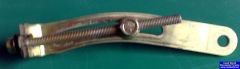
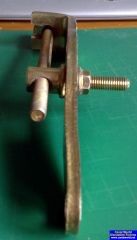
Looks a bit like a Beta Marine high level mount? They certainly used an alternator with that slot on some engines
-
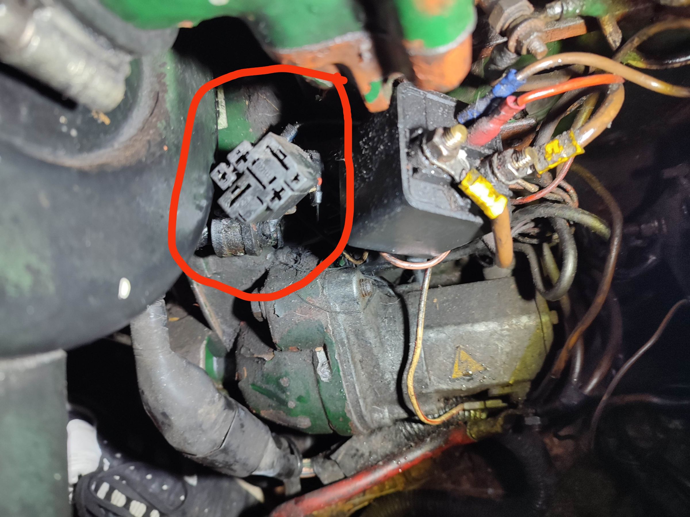
3 hours ago, pt2583 said:
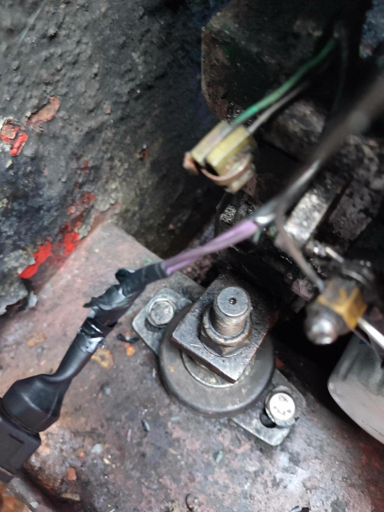
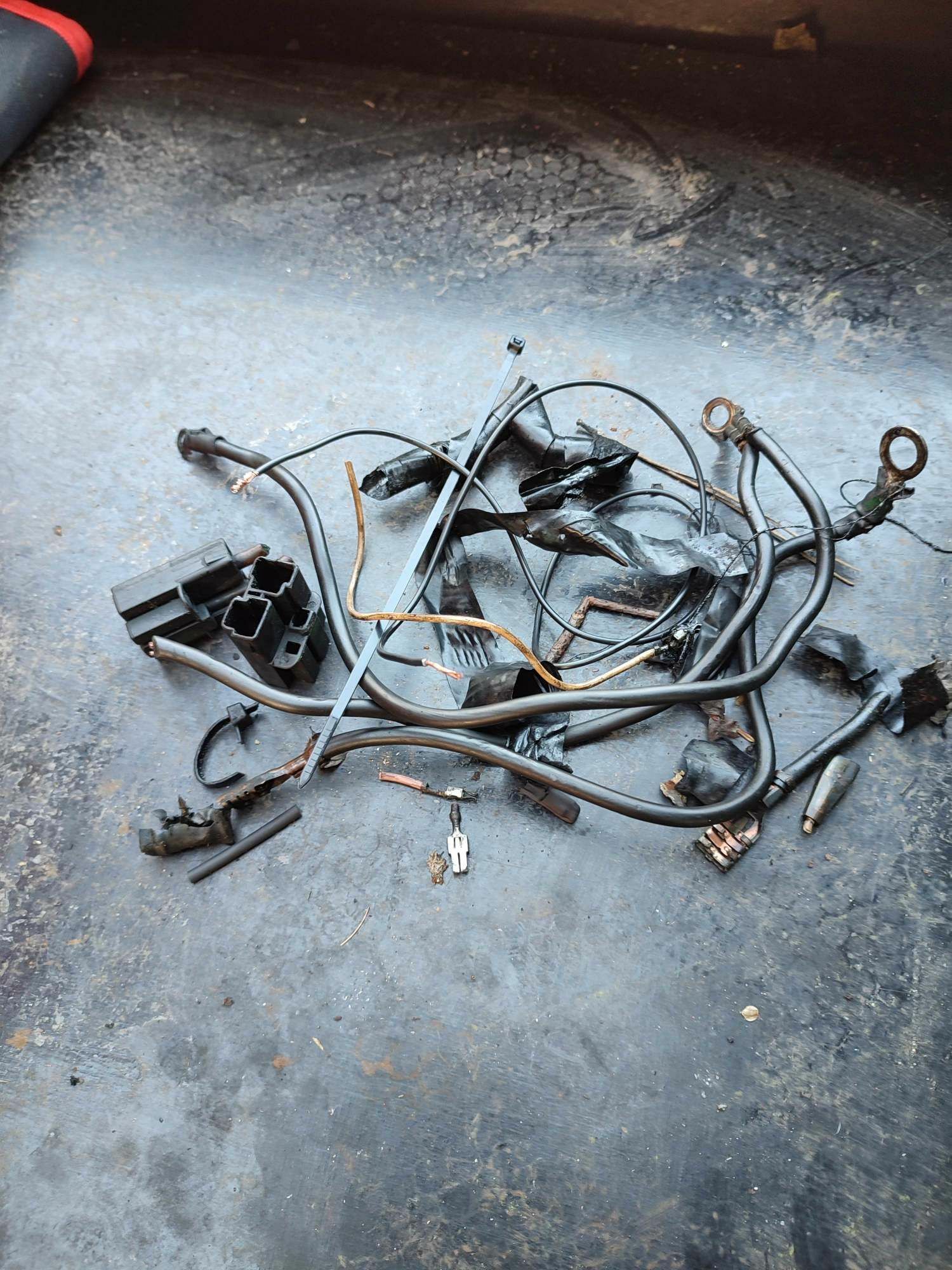
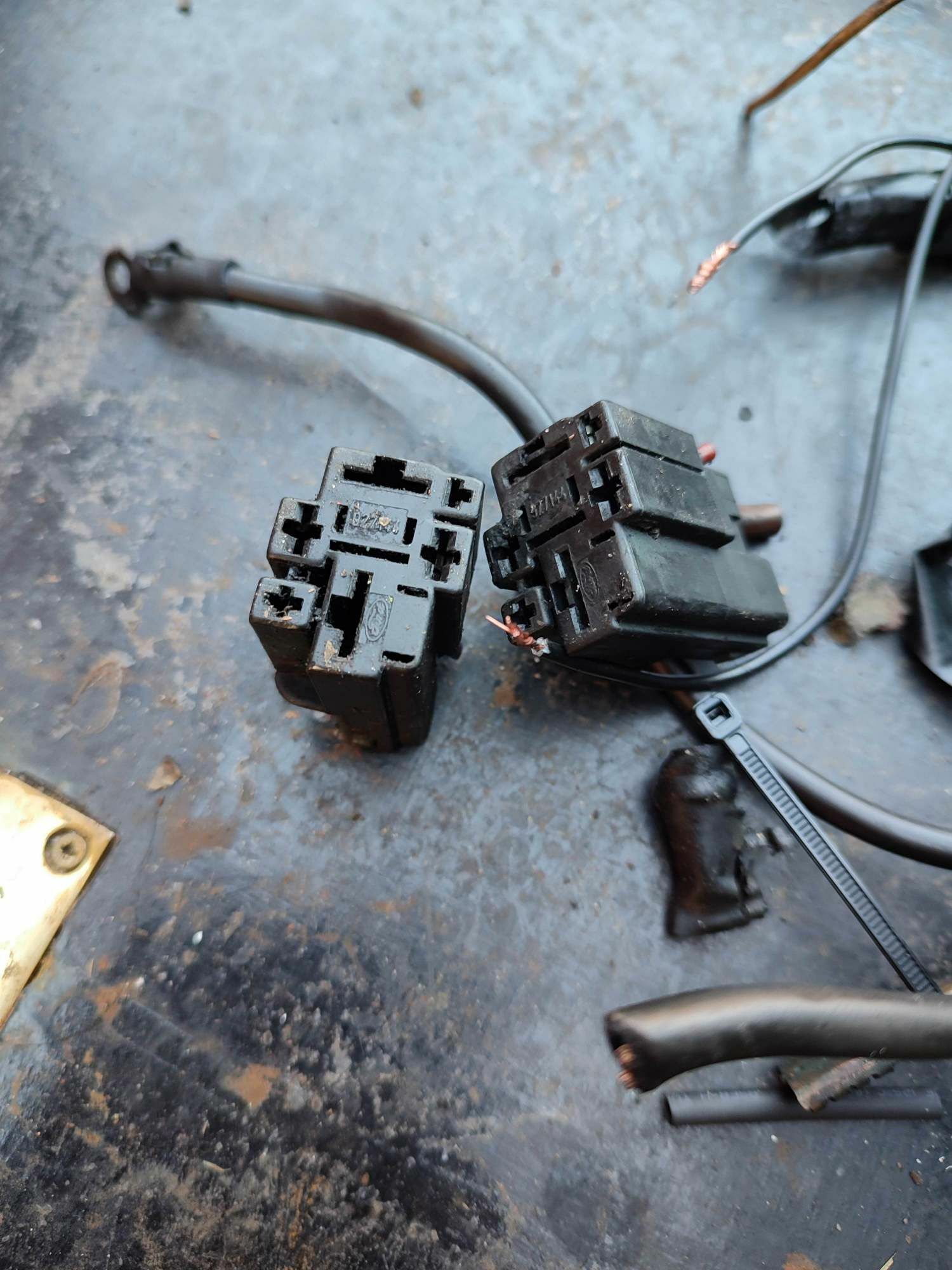
Spent day at boat again today. Further investigation in daylight found that the original combined relay had two connectors (see photo). Colours of all cables matched cct diagrams, however apart from the two 6mm brown cables and red wire from ignition none of the wires were connected. Whoever fitted the new relay ran a new -ve from the relay bracket mounted on engine. Would appear one of the black 6mm cables was ground somewhere but this was also disconnected. This means the alternator has no direct -ve connection, presumably its connection to -ve is via connection bolts to engine.
So on to the temperature switch shown on diagram connected to relay via two purple wires. My one and only switch is indeed fed by two purple wires and test with multimeter found they are the two purple wires originally connected to relays. However as these connectors are no longer connected to any thing my temperature switch is in fact disconnected. I did a resistance test this morning when it was about 6 degrees and the resistance across two contacts of switch was 5.3 kohms. Some Google ING seems to suggest this is about right for this temp. Neither of the switch contacts seems to be connected to -ve through the engine so what I plan to do is run a -ve to one purple wire and then connect the other purple wire to temperature warning light contact on the 11 way plug. So if the switch works correctly (100 ohms resistance at about 100 degrees) the bulb should light. In one of the pictures showing the two purple wires you can also see the two wires from the loom which would be used for a temperature gauge, only installed on deluxe module. Not sure if these would be connected to a second switch where there is currently a plug bolt.

Are you confusing a temperature switch with a temperature sender? A switch would be either open or closed circuit. Perhaps that particular unit on your existing panel used a temperature sender?
-
3 minutes ago, Psychalist said:
Interesting the two cylinder seems to have the relays hanging down the side of the engine where moisture, dirt and oil can get in the connections.
Mine (1997 vintage) has them enclosed in a box:
Despite that, as Tony said, probably an over complication and another source of problems. E.g. Fuel cut-off solenoid jamming due to incorrect alignment, going over-current and tripping. A pull cable is simpler and easier to diagnose.
Interesting, the last one I was in had the relays mounted facing downwards; and yes one of them had vibrated out!
-
3 hours ago, Peugeot 106 said:
Again filters are confusing!
I use 201-55370 and have been told it is bigger than the original filter fitted and more than adequate. My engine is 2004.
Off topic, but still useful to the curious. Most filter manufacturers have cross reference tools on their web sites, and one is probably supplying Listers. They all have one thing in common, and that is the size of the screw thread, and thats about it. The range of internal bypass settings are probably the most curious. It would of course be irresponsible to suggest anything other than genuine parts; but it certainly gives the impression that anything that both screws on and seals would do the job!!
-
20 minutes ago, Peugeot 106 said:
The consequences can have everything to do with the lifters as I understand it. I suggest you read the thread "Lister Petter LPSW3 exhaust spitting" where you will read both Tony Brooks and Steve 56 (a Listers Engineer) saying the same thing. Also I know someone (not on the forum) who was an engineer with Listers developing the Alpha engines telling me the same thing
The LPWS starts dirtier than the LPW. This could well be due to higher compression ratio and blowback as well as time for the precombustion chamber to get up to temperature
This contaminates the oil quicker for a LPWS than a LPW leading to the following (if you don't change the oil at recommended 100 hour intervals)
"The hydraulic lifters then jack open and the valves can hit the piston" (quote Steve56)
"The book says 100 hrs lube and filter change for the LPWS.
The LPWS is indirect injection so that means it runs "dirty " for a while. Mostly when its warming up.
It takes a while for the pre combustion chamber to get up to temperature. That can put pollutants into the oil. Hence the early oil change.
The LPW is direct injection." (quote my Listers development engineer) (He was talking about sticky lifters)
I thought the lifter (hydraulic tappet) problem was well understood. Especially when you replace the cylinder head and talked about on this forum. You can find many other forum members and others saying the same thing and I don't think this is an Urban Myth
Just as confusing and maybe meriting a new thread. Half the world seems to say it is OK to skim the LPWS cylinder head. The other half seems to say that you should replace it with another as the LPWS head has a rim where the combustion chamber is pressed in and this rim is vital for proper sealing though not apparently on the LPW. I think that Lister Petter has a lot to answer for in terms of information with the Alpha. The parts lists are totally baffling given all the build no.s and changes over relatively few years. Not easy for an amateur!
So we agree, its not an issue on a properly maintained engine 😎. I was probably looking from the other perspective. Interesting to note that the filtration system wasn't up the the task of maintaining a supply of clean oil beyond 100 hours, even during development. Cann't remember off hand if the LPWS engine uses the largest of the many genuine oil filters; but clearly a consideration when servicing.
-
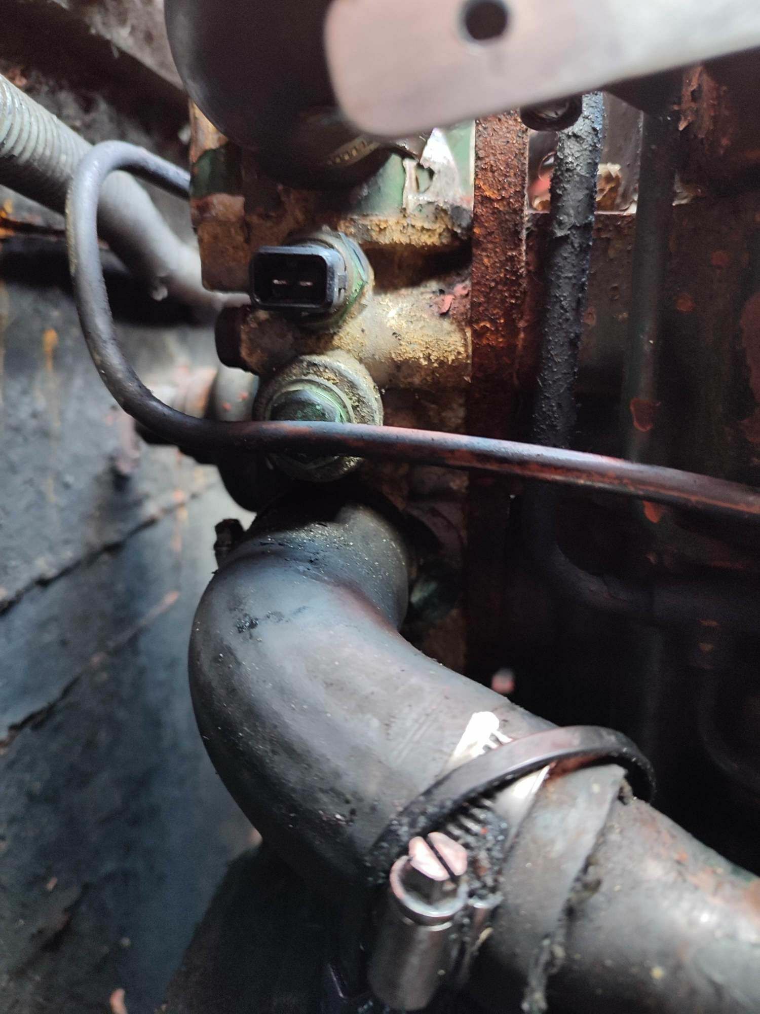
13 hours ago, pt2583 said:
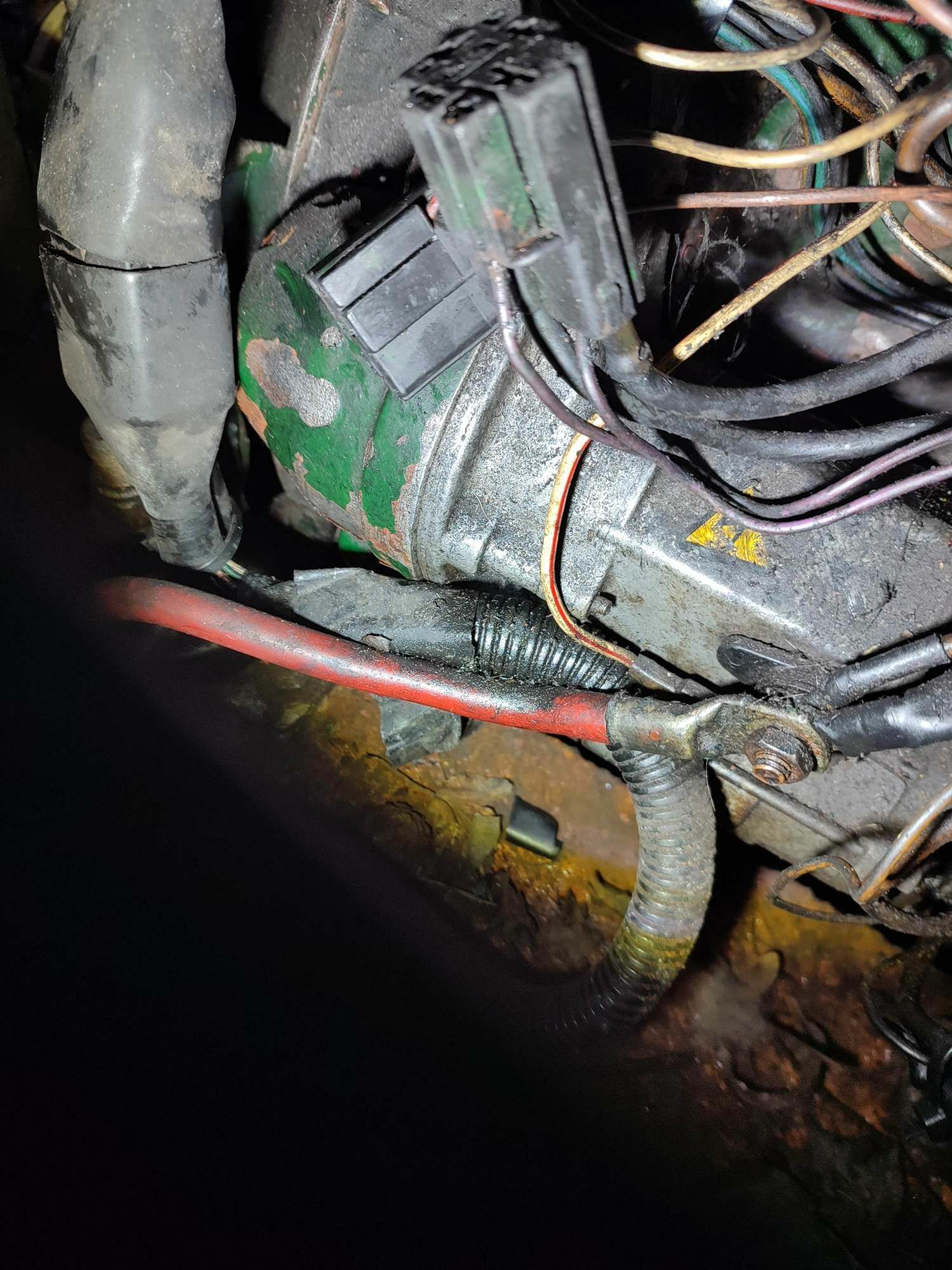
Been to the boat tonight and although it was dark took a picture of the relay and did a bit of prodding around the wires. Too dark to do any proper tracing will leave that for day light hours. Discovered that the relay has in fact already been changed to a simple 4 contact (85,86,87,30) heavy-duty relay. The power in and out to glow plug wires (6mm brown) and +ve and - ve wires have been cut from the original 6 way connector plug and attached to the new relay. This means I don't have pre heat function and more of a worry don't know if the temperature switch wires are even connected to anything anymore. Will now have to trace them out to confirm they are. Perhaps should have done all this first, but have to say its been worthwhile for me as I've learnt a lot from what's been said.
I was lucky enough to have quite a lot of slack (extra cable) in the loom between the 11way plugs on the engine and panel. Everything on the engine, except the main battery connection to the starter and alternator was removed. The loom from the panel was then trimmed to suit and wired directly to the engine. Mine was a LPW3 so you would need to retain or rewire the glow plug wiring on your LPWS; you could upgrade the size of the +ve going to, and the heater supply coming from the ignition switch, or use a simple energise to close relay as currently installed. The panel can be the simplest diagram you can find.
-
On 16/02/2023 at 17:41, Peugeot 106 said:
Yes that is what results when you don’t change the oil, but it is the contamination of the oil caused by dirt at start up that causes the hydraulic lifters to misbehave as I understand it. The direct injection Lpw don’t contaminate the oil as much as the indirect Lpws hence the difference in oil change interval. The engines are pretty well identical other than the piston crowns, cylinder heads, fuel injectors and pumps
please understand I am just an interested amateur not a qualified marine engineer but I do take advice where I can and reckon to be able to do most jobs connected with my boat
Nothing to do with the lifters. Its the difference in compression ratio between the indirect injection LPWS at about 22:1 and the direct injection LPW at about 16:1. The higher compression simply creates more blow by until the piston and rings get up to full working temperature; the best seal being when they have expanded fully into the bore. The pistons and rings will of course only be fully expand if the engine is worked hard enough for it to maintain full working temperature, so more blow by on the LPWS engine is just a fact. Don't forget that the coolant temperature is no indication that the internal components are at full working temperature.
-
41 minutes ago, nicknorman said:
If I understand the question correctly then unusually I have to disagree with Eeyore. If the inverter output is not already tied to earth (ie it’s floating), there is no live or neutral. Whichever is connected to earth becomes the neutral, the other one being the live.
Thanks for that Nick, I bowed out because I had doubts when I reread the test lamp results. Another day at school.
-
I’m happy to advise on the potential danger of creating a live to earth connection , but you should contact the manufacturer for further advice on a neutral to earth link.
-
It’s worth noting that the French version of the Schuko can have an earth pin in the socket. So it’s possible to use one of those to ensure correct polarity; or just fit a UK socket to the inverter.
-
Yes, because if its the wrong way round you will have an earth to live connection.
-
24 minutes ago, Tony Brooks said:
It would not surprise me if extended oil change periods did not have something to do with it as well. Trains seem more likely to be high mileage, high intensity use. Just guessing though.
There is a surprisingly high percentage of idling as trains can often coast for many miles once up to speed. The effects of idling being offset against the high power demands of accelerating away from a stop. This sounds a bit like the "Italian tuneup" advice often given to boaters with smokey engines, a high power run on deep water to get everything up to correct temperature for about half an hour and alls well again. So perhaps a little synthetic is fine providing you can get it up to full working temperature once in a while?
That said, I ran my nearly new Lister LPW3 on Mobil 1. It was slightly undersized and over propped for a 62' nb, so no issues with getting it up to temperature, with the added bonus that it would idle smoothly from start up in sub zero temperature because the thinner oil didn't "gum up" the governor linkages which are internal to the engine.
-
42 minutes ago, MtB said:
This site says in essence, mineral oil has molecules of varying sizes while synthetic is built up out of molecules all the same size.
https://www.machinerylubrication.com/synthetic-oil-31800
I've yet to find any discussion of why any engine manu would specify not to use synthetic (as seems to happen with boat engines). It seems to have no major disadvantages.
A fleet of trains that I worked on during their warranty period had Mercedes engines which used a synthetic oil. The Mercedes tech support team seemed to think it was needed in order to keep the oil inside the engine! This of course makes perfect sense as you can design/specify seals to deal with oil molecules of a consistent size.
-
4 hours ago, Tony1 said:
In fairness the canaline manual hedges its bets by saying 'check the PRM manual' and then 'always use ATF'.
It looks as if the canaline manual is out of date in insisting that you use ATF.
But ATF will work ok, and I've got it now- so for this service, that's what will be going in.
Next year I'll switch to engine oil.
I wouldn't be so sure about that https://www.prm-newage.com/help-centre-marine
The change from engine oil to atf was related to the time it takes for the oil to be 'squeezed out" from between the cone clutches during engagement. In some circumstances engine oil delayed the engagement of the clutch resulting in slipping and rapid wear of the linings.
-
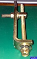
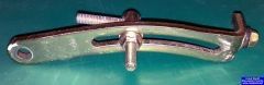
This tensioner was liberated from an Isuzu engine. Not a marine engine, but the same type as used by HMI when producing their range. Might be an Isuzu part.

-
Some diagrams in this:
-
Did you use a small load, say a 60w lamp, whilst testing? This seems to settle things down a bit. I've experienced units that displayed a harmonic frequency on the meter when off load. The worst one had sheared the screws holding the stator coils to the frame allowing them to rotate; with only the cable connections (briefly) holding everything in place!
-
 1
1
-
-
The maintenance requirements are quite simple:
"The SL model alternator similarly requires no regular mechanical maintenance. It is, however, fitted with slip-rings and brushgear which require regular attention.
Inspect brushes and sliprings at 500 hour intervals. Replace brushes when they are worn to a depth of 8 mm. The new brush should be bedded using a medium grade abrasive cloth. If the sliprings are pitted or badly marked the rotor should be removed and the sliprings lightly skimmed.
The alternator must periodically be inspected and any accumulation of dirt or oil must be removed. Air inlet and outlet openings must be kept unobstructed."An accumulation of carbon dust from the brushes (normal wear) can cause some interesting symptoms, depending on where it settles.
-
16 minutes ago, Tasemu said:
The end cap of the alternator appears to push up and into the insulation on the side of the acoustic box. I'll try to have a proper look to see if i am able to access the screws to remove the cap. Looks really tight though.
You will have to dismantle the end of the acoustic box to get to the circular end cover; it requires a clearance of at least its own length to remove it.
-
The avr is attached to the same bracket as the brush gear, under the end cover. The box on top of the alternator containing the sockets and circuit breaker is fitted by Beta.
-
46 minutes ago, Tasemu said:
I'm fairly certain it is a BL105 then as I cannot see any AVR on the unit. I have found the speed adjustment screw though. I'm hoping very much that I can adjust it and get a lower voltage out. Will report back with results.
Hoping this picture may help? Unsure what this AVR looks like.
Adjusting the engine speed will change the output frequency; and of course a frequency setting on your meter is the ideal way to set the engine speed.
-
Is this the voltage from a meter on the control panel or from a multimeter? A multimeter needs to be a “true rms” type, otherwise it may give you the voltage you mention by default.
-
16 minutes ago, Tom and Bex said:
Not just dogs but all animals and all antifreeze to my knowledge. Also children at high risk - it tastes sweet hence it's attractiveness.
And for us old enough to remember such things, part of a scandal involving some wine suppliers!
It is of course the corrosion inhibitors that primarily determine the life of "antifreeze".
-
2 minutes ago, LadyG said:
What a surprise.
Anything wil be "compatible" if the engine cooling system is drained, flushed, and replaced
Not strictly true as some products are material/manufacturer specific, but I take your point.


Alternator mounts
in Boat Building & Maintenance
Posted · Edited by Eeyore
Post a picture of the holes in the mounting bracket if you can.
Disconnecting the battery, unless there is a switch in the circuit. Make sure everything is switched off before reconnecting the battery, otherwise the slight sparking can be a bit alarming.