Ewan123
-
Posts
668 -
Joined
-
Last visited
Content Type
Profiles
Forums
Events
Gallery
Blogs
Store
Everything posted by Ewan123
-
The creator of the app (Tom Sapey) posted on the London Boaters facebook group a few weeks ago - he's just released a new version specifically to address crashes on some Android phones. He says to get the new version you'll need to completely uninstall and reinstall the app. Might be worth a go? Apparently this version misses out a few features but they will be reinstated later on.
-
Have Brompton made the perfect towpath/boating bike for liveaboards?
Ewan123 replied to Tony1's topic in Living Afloat
I came across a secondhand folding mountain bike not too long ago, almost bought it. The wheels were almost full size so obviously the folded size wasn't tiny, but was still significantly more compact than non-folding bike. -
This might work for those not in the group: https://www.facebook.com/100063740852500/posts/pfbid02sDqoG6GQMA2BM95j4WNjCYGSpttQ5hwAS3kjiRE3YyR4uodyALHPvWrFETW5ACMxl/?app=fbl
-
Understood, thanks for your time. Yes I thought that's why it wouldn't be ideal, thanks for confirming.
-
I might have been unclear in the first place, apologies - the leisure bank comprises two Lithium and one LA in parallel, so we've got that LA buffer to protect the alternator when the Lithiums disconnect during charging. Oh we do have a bow thruster battery as well... I had thought this was in parallel with the engine battery but now that I think about it, I'm not sure why I thought that. Time to follow some wires again I think - I guess the split charge diode was probably wired to that, and is what I've wired the relay to as a result. Which would explain why the relay appeared to click nicely but not affect the leisure bank charging. Assuming that's the case, is it a daft idea to parallel the starter and bow thruster batteries (the latter is ~58ft away in the bow) in order to have just two banks that the relay can connect?
-
I also disagree with the premise of OP's post. The only angry boater I've encountered (one that I can recall in over three years) was last weekend, shouting at me to slow down. (No I wasn't going fast, it's just that his boat was moored with three lines straight down from the roof, not one at either the bow or stern, so unsurprisingly his boat wobbled!)
-
A small defect on the non-slip coating of one board became apparent after a couple of weeks. I asked Thorn Marine whether they could recommend an easy fix (I'm not too fussy about appearances but untreated over time it would have reduced the lifespan of the board) but they just said straight away that they'd make a new one to replace it free of charge, and they dropped it off to the boat. Things can go wrong with the best of places but how they deal with that can say a lot! Very pleased.
-
Given that the relay works and I can get the small wires to the right places now (thanks for all of the advice to get me that far), it seems like it can only be an incorrect connection to the batteries now though, does it not? I'm happy to be corrected, but I'm not sure there's much difference between a split charge relay working with two LA banks vs one LA and one hybrid LA/lithium. The hybrid bank will draw more power for longer, so care needs to be taken with the alternator, but otherwise no difference? I understand the potential issues with the lithiums working an alternator too hard - I'll be monitoring the Amps from each alternator as well as the temperature of the alternators to ensure they're not getting overworked by the lithium. As it stands, (no B2B, I've not installed any long wire system as there seemed to be enough resistance in the system already, such that it wasn't necessary for the domestic alternator) the domestic alternator is charging the lithium hybrid bank without problems - the alternator (rated 70A) remains below 80°C and puts out no more than about 50A at the most, so I believe that's within the capabilities of the alternator (all I changed in the charging system when adding the lithium was disconnecting an external Sterling regulator from that alternator). I'll monitor the same on the engine alternator once I get the relay working and make some changes if the alternator gets worked too hard - I'm aware that since it already gets to a good charging voltage without an external regulator upping the voltage, I might need to keep a closer eye on this one to be sure the lithium doesn't make it work too hard. So... two alternators charging the engine battery, and the relay connecting the engine bank and domestic bank when the engine is running? I'm not sure I understand the significance of this different approach. Thanks for your continued patience and assistance.
-
I've tested the relay with wires across a battery, it clicks nicely. I did this with the engine running too - nice click, no change in charge behaviour. So that narrows it down to the other two connections on the relay! The port/starter alternator is definitely correctly connected to the relay 👍but the connection to the leisure battery positive... I used a cable that was connected to the diode splitter which I think should have been right, but it's a sod to follow - seems to go through the inverter-charger (and at the very least takes a much more circuitous route than apparently necessary for the relay). I think this might be the only remaining possible issue. Spare time is running out now and I might not have a cable spare to easily rectify that connection, but I'll report back in a few days hopefully.
-
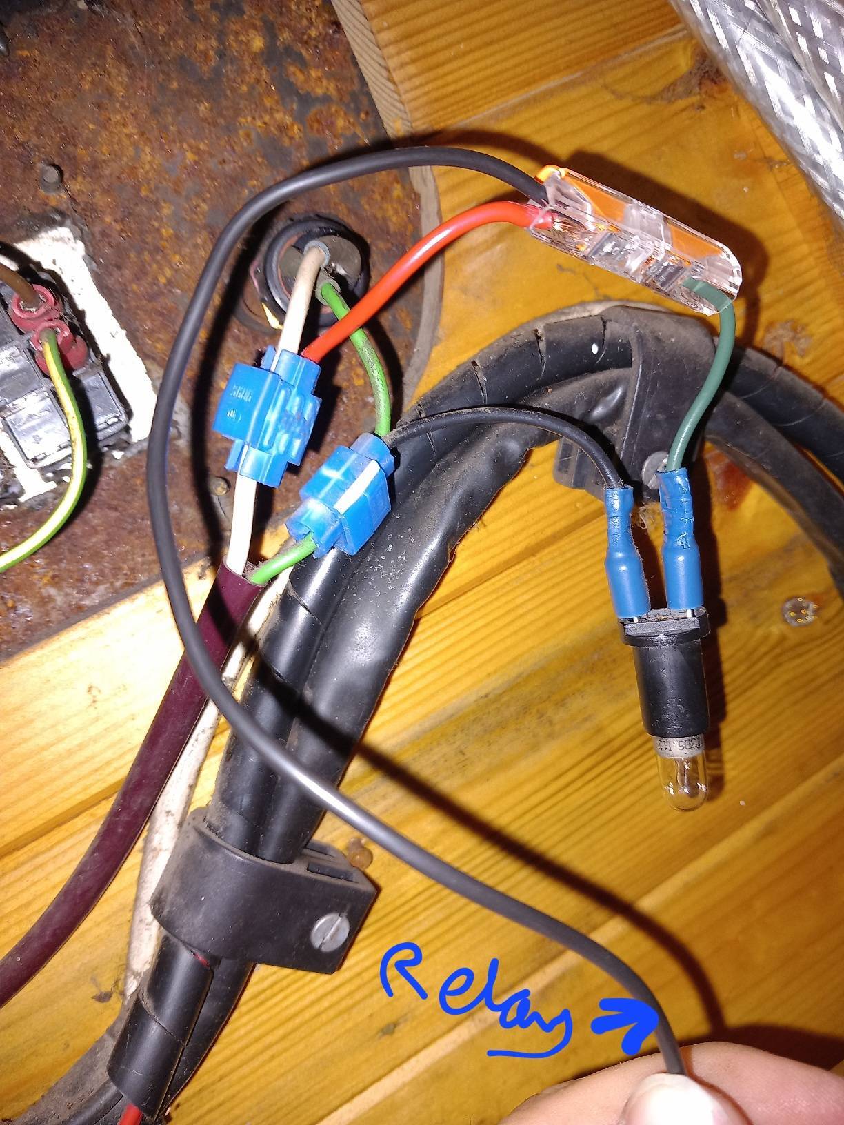
I've just checked with the multimeter and the white cable is positive with ignition on (though across each bulb I only measure about 8.5V?). I tried swapping the relay cable to the other side of the visible bulb but no difference - in theory would I want to connect the relay cable to the green negative cable before it splits off between the two bulbs, so it's getting the full power? (This is more for my education at this point, I've ordered a piggyback spade connector for the D+ and will be careful of shorting, thanks).
-
I'll explain what we're looking at there as best I can: there are two bulbs, one visible in the image (dark green and black wire attached, which I put the relay cable onto with the wago) and one we can only see the back of (white and green wires attached) which is in the engine control panel. I'm not sure what the purpose of the one we can see is as it just hangs around in a closed cupboard. Both bulbs illuminate with ignition (along with the buzzer sounding) and go off shortly after ignition. There's just the one -ve cable from the relay here going into that wago connector. The other -ve from the relay goes straight to the battery negative post. I think that may well be easier, I just didn't have any appropriate connections to do it with at this moment. I'll get a proper spade splitter to go straight into the D+ on the alternator.
-
Solar controller into float too early
Ewan123 replied to Ewan123's topic in Boat Building & Maintenance
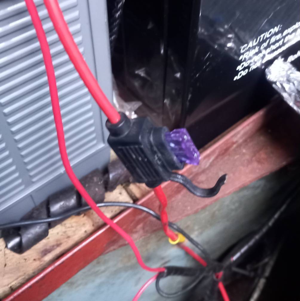
Replacing the suspect fuse holder didn't change anything, but at least it's replaced with one that's not scorching itself! -
I did something which I thought was what you suggested here but I may have got confused... I've joined the relay cable to the cable running to/from the alternator warning light bulb - does that sound/look right?? It doesn't appear to have resolved the issue though so I'm guessing not. (Sticking them both into the wago connection was just a quick method to test)

-
I did splash out on a genuine Durite part with similar thoughts, didn't fancy risking a cheapo.
-
Well I'm not too surprised that I failed to follow the wires properly to identify the connections 🤦♂️ thank you both. I don't expect to be getting much more than 100A out of the two alternators, so hoped the 200A relay should do well enough.
-
Solar controller into float too early
Ewan123 replied to Ewan123's topic in Boat Building & Maintenance
Well I've replaced the suspect fuse holder, now just to wait for enough sun to see if it makes a difference 😐 (the voltage displays were showing equal without full sun, before and after the fuse change). -
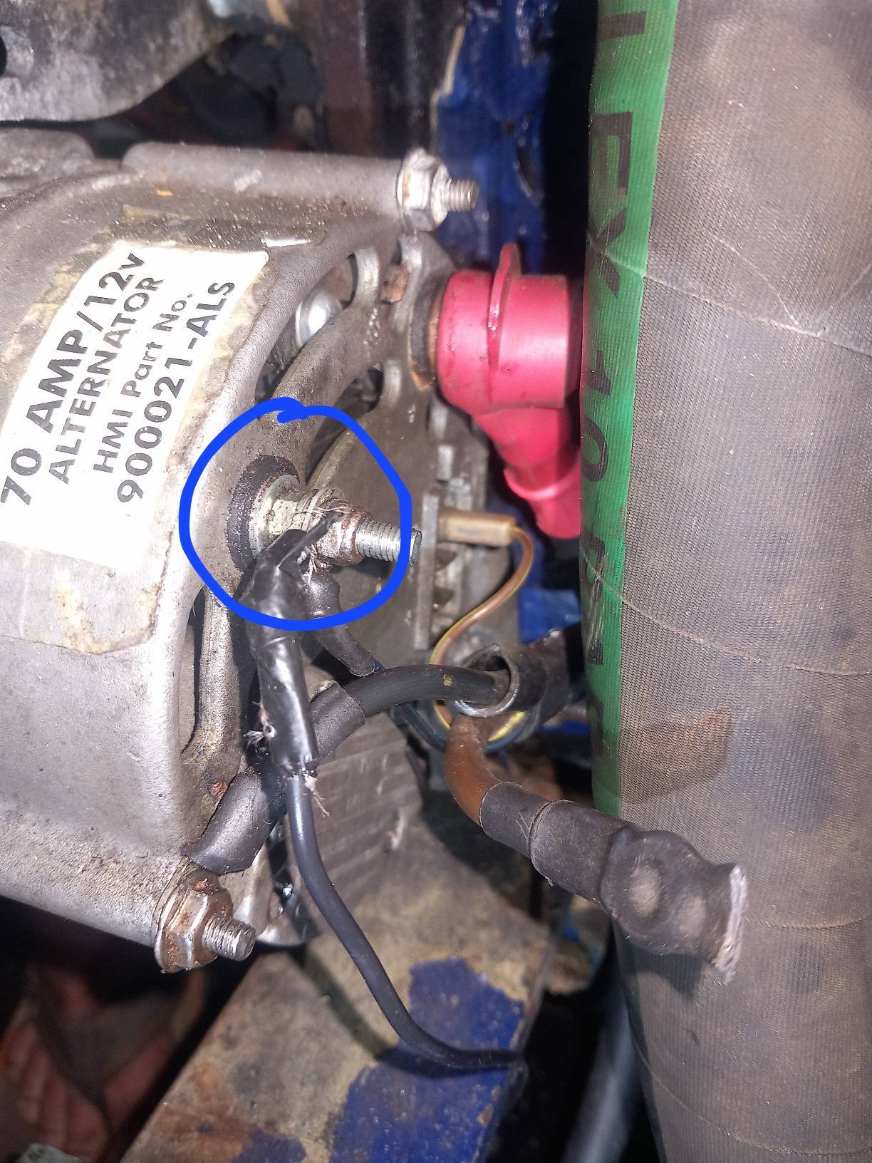
I recently installed a split charge relay (replacing a split charge diode), with thanks to @Tony Brooks for http://www.tb-training.co.uk/MarineE09.html 👍 in order to get the port alternator to join the leisure charging as that's a hybrid lithium bank so can take much more than the 50Aish it's currently getting from just the starboard alternator. However, it hasn't been connecting the battery banks when the engine is running. The port alternator is only charging the starter and bowthruster bank, the starboard alternator is only charging the leisure bank (I can tell as each alternator matches the voltage of each bank and there's a difference between the two, and I'm only getting 50Aish into the Leisure which seems right for one 70A, not two together). I think I may have identified a possible cause, but I don't know what to do about it (if indeed it is the cause). I've got the relay energising wire going to the warning lamp (circled blue in the image below, marked "W" on the alternator case. This measures 0V with the engine off, and only half the charging voltage with the engine on, e.g. charging at 14.2V, this connection shows 7.1V (measured with the alternator case as the -ve). I can't find another connection on the alternator that is 0V engine off and charging voltage with engine on. Should this connection not be getting up to the same as the charging voltage? Could this be the reason for the relay not connecting the battery banks?
-
That's bad luck, we were moored in that same spot (albeit in winter I suppose) and no one got close to bumping us.
-
Solar controller into float too early
Ewan123 replied to Ewan123's topic in Boat Building & Maintenance
Thank you 👍 -
Solar controller into float too early
Ewan123 replied to Ewan123's topic in Boat Building & Maintenance
I don't think I understand - what do you mean by positive ground? And what would be the problem? -
Solar controller into float too early
Ewan123 replied to Ewan123's topic in Boat Building & Maintenance
Update: I checked the voltages again first. In full sun, batteries not full. Controller measured on terminals matched its own display: 13.6V Battery measured on terminals matched the Mastervolt display: 13.3V (I got some charge in yesterday by telling the controller to float at 14.2V and kept an eye on it) This fuse (35A) is suspect - it's in the positive cable between controller and battery and one of the contacts inside was scorched. I replaced the fuse but it didn't connect (V on controller dancing wildly around) until I scrubbed it, now controller is back to a steady 13.6V. I don't think I have the means to bypass the fuse and check whether this is the culprit, but I'm replacing it ASAP anyway. Could this be enough to explain it all? The cable between controller and battery looks to be 3mm² and felt just slightly warm to the touch (noticeably different to other cables nearby). There's a max 26A of charge from the solar so while the cable seems adequate, an online calculator suggests there might be about 0.8V dropped (it's about 2.5m in length) which seems high. Could that also be contributing, ought I increase that cable to say 6mm²? Showing my ignorance here, but wouldn't a voltage drop in that cable result in the controller showing a voltage that's lower than the battery?
-
You might find you have a few cruises in winter that unexpectedly end up in the dark. It's a lovely thing to do intentionally as well! Cruising at night would be a good time to avoid lights around the stern anyway, you want your night vision relatively unspoiled. Personally I just use a torch with a magnetic base positioned wherever necessary if I'm in the engine bay/weedhatch in poor light conditions. Maybe a headtorch for actually seeing down into the weedhatch if needed.
-
Solar controller into float too early
Ewan123 replied to Ewan123's topic in Boat Building & Maintenance
It does look to be a deliberate recommendation (http://www.sp-inverter.com/eMPPT30-Solar-Charger-controller.html)... I'll admit I don't know where the fuse actually is on ours, but thanks I'll check that out. I might not be able to check and report back soon but thanks for the suggestion, I'll look at that. -
One thing that I don't think others have mentioned - small portholes can be advantageous for security as well as privacy. When I've seen posts on Facebook about break-ins, a significant proportion have photos of the big windows having been smashed to gain access. A small porthole isn't attractive or even viable for a break-in. We have all portholes (about 25cm diameter with 'hopper' opening top half, so metal bar across the centre) with a barred 'houdini hatch' skylight (which is great, the boat doesn't feel dark inside with this). No one looks in, which is really nice. No one can break in through the window - that's also nice. It is a compromise - I can see the view outside if I want, though of course there would be more view with a bigger window. I am envious of boats with a side hatch on both sides, that's definitely good. We sometimes cruise an extra 30 mins or so to wind and get our one side hatch on the water-side. Our skylight does of course drip, but it's worth it overall. It can be lovely to lie back on the sofa and watch the sky (/stars/clouds/moon/arse-end of a bird drinking from the water collected on it). We also use it to pass lunch/dinner/drinks up to the roof-deck. Access to the roof is very much a personal preference - you really need to have a go at doing locks/living life with/without to know which is best for you. I like easy walking along one side of the roof for getting to lock ladders, plus we use the front quarter/third of the roof for decking where we enjoy eating/relaxing in warmer weather.
-
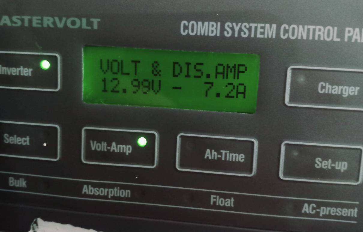
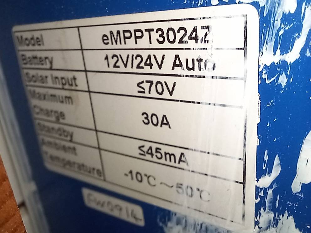
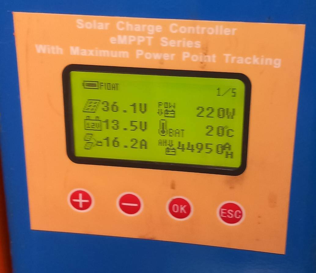
Hi folks, I think I've got a problem with our solar controller. It seems to go straight into Float mode (13.5V) without first going up to Absorb (14.4V). Here's the context: Controller is eMPPT3024Z (manual: https://sun-energy.com.ua/image/pdf/eMPPT30manual.pdf?srsltid=AfmBOoqcFKmUM_frZ4O_Q_z2aPwqy5_JSG1MwHzYkN9YO54xu7QTcE-b) Float set to 13.5V, Absorb set to 14.4V Batteries are a hybrid of sealed lead acid (LA, 105ah) and LiFePo4 (2x200ah from LifeBatteries, with internal JBD BMS). I don't think the lithium could be causing this - it was behaving normally for a good while after installing the lithiums and I believe the recommended 14.6V charge and 13.8V float should play nicely with the solar controller's 14.4V and 13.5V. There's a bow thruster LA battery at the other end of the boat, connected to the LA engine battery. These are connected to the leisure bank with a 200A relay. Not likely to be related? The actual voltage of the batteries (shown on Mastervolt controller measuring at the shunt, I've checked this is true with multimeter on batteries) can be anywhere below 13.4V when I notice the solar is in Float at 13.5V (though they never really go much below 12.8V at rest). Example battery voltage and controller status today when the solar controller is in float: This a common occurrence now but occasionally it works as expected 😐. Does this sound like the solar controller misreading the battery voltage? It's always been off by 0.1-0.2V but I thought that wasn't unusual for a solar controller. Could there be a setting in the controller that I'm missing? I think I can only change the Float and Absorb voltages. Any thoughts or ideas would be much appreciated