Tasemu
-
Posts
453 -
Joined
-
Last visited
Content Type
Profiles
Forums
Events
Gallery
Blogs
Store
Everything posted by Tasemu
-

Replacing current inverter and charger with Victron Multiplus
Tasemu replied to Tasemu's topic in Boat Equipment
Yeah absolutely, i'm so used to this setup of manually switching that I'm honestly not worried about forgetting. Basically just can't get down into the bilge to rewire my generator until the weekend and i've uninstalled my old inverter already haha. Like so?
-
Replacing current inverter and charger with Victron Multiplus
Tasemu replied to Tasemu's topic in Boat Equipment
I got the multiplus for a decent price and its been sitting there for a year while I worked out how to get a clean 230v from my diesel genny. I would like to be able to use the inverter too though -
Replacing current inverter and charger with Victron Multiplus
Tasemu replied to Tasemu's topic in Boat Equipment
I was under the impression that it can swap between charging and inverting automatically, however because the ac output loops back into the selector switch and then back into the AC input of the victron, i had thought it would detect it as a charging current. -
Hi all, i have created a couple of flow charts below which encompass 3 setups i'm playing around with in my head. The current setup is how i have it now. It has a separate inverter and charger, i manually set the selector switch and the charger switch when i want to swap from inverting to charging. I have a victron multiplus I want to install and in the short term to avoid a large rewiring situation in my engine bay I was considering the Temp Setup for minimal wire chaging. It should just be a matter of swapping the sterling charger for the victron and swapping the inverter cable to the AC out on the multiplus. It would appear to me from this setup that i would still need to manually swap between inverting and charging to avoid the multiplus charging off itself. I have two main questions I was hoping to get advice one for this. 1: Is there a better approach to the temp setup that would not require rewiring my generator output? 2: Does the New Setup actually make sense as an appropriate way to configure this? Thanks in advance for any and all advice!
-
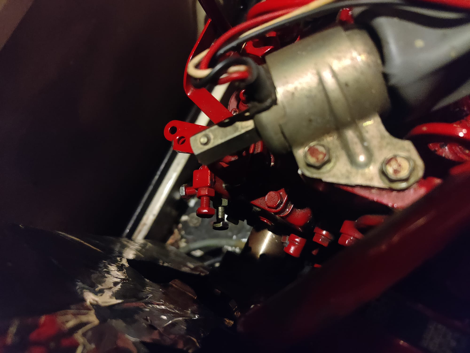
Hrmm. the only way i know to adjust the engine speed was from this bolt that pushes the adjuster on the engine. I've had to push this the whole way in, you might hear the engine sounding quite fast on the video. Perhaps i'm adjusting the speed from the wrong control? EDIT: The bolt in question is the steel un-painted one which moves the larger red leaver under the shorter red one. No idea why, but when running with a ~2kw load the voltage climbed from 230v to 236v... The hz went down to 48.7hz. But clueless on that. Currently using the air fryer to heat some chicken wings to see if the engine overheats with the current rpm required to get 50hz.
-
Hi all, i promised i'd be back with results so here I am! I found this schematic (attached to post) online for a very similar markon generator head and figured that if I disconnected and isolated Z3 and Z2 from the rectifier then it should no longer be supplying the slip rings with a voltage. After doing this I installed the F1 and F2 cables from the slip rings to the old AVR and connected them to the new SX-460, i also used wago connectors to tee off the live and neutral from one of the generator outlets to supply the SX-460 with power and voltage sensing. When starting the engine nothing exploded and i was getting around 120v @ 42hz. I slowly increased the speed of the engine until the speed bolt (pictured) topped out at about 49.6hz. I then slowly raised the voltage potentiometer on the SX-460 until I got a clean 230vac from the outlet at no load. I have included a video of the results, and this appears a success at first glance but i'd appreciate a sanity check on my methods, and also one question. Is it normal that my little beta engine for the generator only reaches a top speed of ~50hz? The bolt wouldn't go any further. Thanks so much for all the help so far and any answers to my above 2 questions! Results Video:
-
So after looking at this video, i think it might be possible. He's putting a sx460 on a Markon SC21G (mine is a Markon SL105), and he seems to have a bridge rectifier like mine and a choke like mine, only difference being the resistor method over my old avr. He's disconnected all that stuff and the sx460 seems to be working. As it looks like i have no option but to suck it and see.. I guess i'll come back with the results once i work up the courage? Cheers!
-
I think i understand yeah, assuming i have no loads connected to the generator. Do you think this would be something worth testing? Or would you say there would be a significant risk of damaging my generator?
-
If the rotor magnets were permanent, then wouldn't it not require a field winding voltage at all? I'm still new to a lot of the theory of all this.
-
I think i may have a shot at disconnecting the rectifier completely from the rotor windings, as the SX460 takes the 230v output from the generator and uses that to supply a dc regulated field winding voltage. I feel in my gut that it would work... I am terrified about damaging my generator though
-
Yeah i have a link to a digital copy if needed. Any help would be appreciated highly, I have a new victron multiplus sitting there collecting dust for months now as i can't use it with the current avr so I need to sort something out 😅
-
This might be crazy, but if i disconnected the rectifier from the slip rings... could i not use the sx460? As it connects to the slip rings through the brushes? In my mind it would work as the field winding would no longer be powered from the auxillery coil, but instead powered from the sx460 through the brushes?
-
Cheers, i think it does explain why i'm getting voltage after disconnecting the old AVR.. Though i'm still puzzled how i'm supposed to install this SX460 if the slip rings are getting power directly from the full bridge rectifier... Yeah it looks like the SX460 actually supplies a voltage to the slip rings rather than siphons it off from there. So i'm guessing its incompatible
-
So i'm totally stumped... I set the generator to 50hz and it was outputting 280v with the old AVR. I then installed the SX460 and its still outputting 280v with the voltage trimmer down to minimum. Then i even disconnected the wires to the brushes.. which as far as i know should be powering the rotor windings through the slip rings and its still outputting 280v! Its almost like the generator is totally ignoring the AVR's and getting power to the slip rings from somewhere else... I'm so confused. For now i've set the Hz back to 42 and its dropped the voltage back to 230v. Can anyone offer any advice on what might be going on here? I managed to find this online... i'm guessing that this kind of AVR reduces the power to the rotors, but it will work without an avr but at a higher voltage... So i'm guessing that the SX460 wont work with it... I'm honestly not sure. Info: The SL105 The SL 105 range have two stator windings. The main winding is used to provide the alternator’s output power and therefore, will be connected to the load. It typically consists of two 120V windings, brought out to terminals by four leads identified as U1 – U2 and U5 – U6. Connecting these windings in series [link U2 to U5] will provide the most commonly required 240V output between terminals U1 and U6. The output leads of the auxiliary winding are marked Z1 and Z2 and this winding provides power for the excitation system. The output of this winding is connected, via a series connected choke, to the ac input terminals of a single phase full wave bridge rectifier, which is the 4-terminal solid state device mounted near the choke. The dc output of the bridge rectifier is connected to the rotor windings via the slip-rings. The positive (+ve) lead is identified by the marking F1 [X on old alternators] and this is connected to the slip-ring closest to the alternator bearing. The negative (-ve) lead being marked F2 [XX on old alternators]. AGN 102 ISSUE B/13/21 This excitation system is designed to generate slightly more excitation than is really needed for any condition between No-load and Full-load. Excess excitation is diverted away from the rotor [field] windings by a solid state Automatic Voltage Regulator [AVR]. The AVR is designed to momentarily short-out the excitation voltage being supplied to the slip-rings and by so doing, it reduces the effective level of excitation available to ‘flow’ through the rotor winding. The alternator’s output voltage is controlled by the level of excitation current flowing through the rotor winding. The AVR senses the voltage of the main winding and compares this voltage level with the ‘set’ voltage level and maintains a constant output voltage under load conditions by constantly adjusting the level of the excitation being applied to rotor winding. As explained above, the alternator actually generates more than required excitation and this is reduced by the action of the diverter type AVR. This means that the alternator will operate without an AVR, but will generate higher than nominal output voltage. Without the AVR being connected, the output voltage will be some 300V under a No-Load condition. If load is applied to the alternator, then this 300V will reduce in proportion to the level of load applied such that at rated load the output voltage will be some 250V. In emergency conditions, where the alternator must be operated without an AVR, the output voltage can be reduced to acceptable levels if the engine speed is reduced.
-
Yeah mine has a box on top of the alternator part of the genset, its quite large and only contains the brakers for it... perhaps i could mount in there 🤔
-
Potentially stupid question, but if i replace the MD1C markon avr with the SC460, could i use some wire extensions to mount the avr outside the generator for easier access in the future? Pulling the whole damn thing apart is a nightmare.
-
Cheers, i do have digital copies so should be fine but thanks for the offer. I'm hoping replacing the the AVR will sort the issue rather than the alternator side of the genny. Mostly for money and the pain of the job in a confined space on the boat. Hence why this SX460 avr looks tempting at only ~£20.
-
Hi all, a few might remember my old post a while ago regarding my diesel generator outputting around 270v @ 50hz and how I was going to replace the AVR. Long story short I still haven't had the guts to tear the generator open again but am finally getting ready to take the dive. I was looking online and a lot of people appear to be recommending the SX460 as a decent and cheap AVR for generators. I'm wondering if it would be a like for like replacement for my old AVR that is very difficult to find nowadays... The mounting holes seems different but... Zip tie magic? Cheers for any advice!
-
Its highly likely that none of the pictures you have are geotagged, only geotagged pictures are usable for logging location. Its a setting on your phone you will need to turn on in order to start geotagging the photo's you take.
-
V1.0 has been approved by the google play store and is available here: https://play.google.com/store/apps/details?id=com.driftdiary.app&pcampaignid=web_share Please post any feedback or issues you have with using the app here, its still early days. 👍
-
Just send you an invite on the face space and followed you on github 👍
-
HAHA! This is flipping uncanny timing. The app looks amazing mate and i'll download it today to check it out. Got a link to the repo? I'd love to have a squiz at the code.
-
Just don't upload that picture, will still work fine 😉 Sure am mate 👏 Also might be worth reminding that this app sends nothing to nobody, but if CRT ever asked you to prove it. You press the PDF export button and have a brewski. I ain't trying to change nothing major here.
-
Not at all mate, i got tough skin. I genuinely think all these arguments can be used to change/improve it. Free feedback mate. Actually, as long as you have taken pictures of your boat then you can install the app and import them, it should work as expected. In the current build anyway... Once i switch it up as you suggested this may be less viable. 🤔
-
This is the exact reason why i made it yeah. I have run into this issue myself and was able to sort it easily, but i like having the data ready if I ever need it.