


Mikexx
-
Posts
541 -
Joined
-
Last visited
Content Type
Profiles
Forums
Events
Gallery
Blogs
Store
Posts posted by Mikexx
-
-
This is a low priority task and conscious the time it has taken me so far.
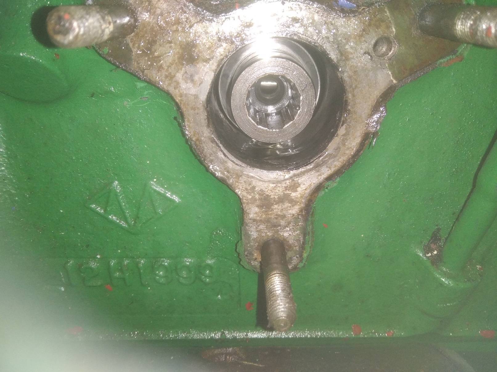
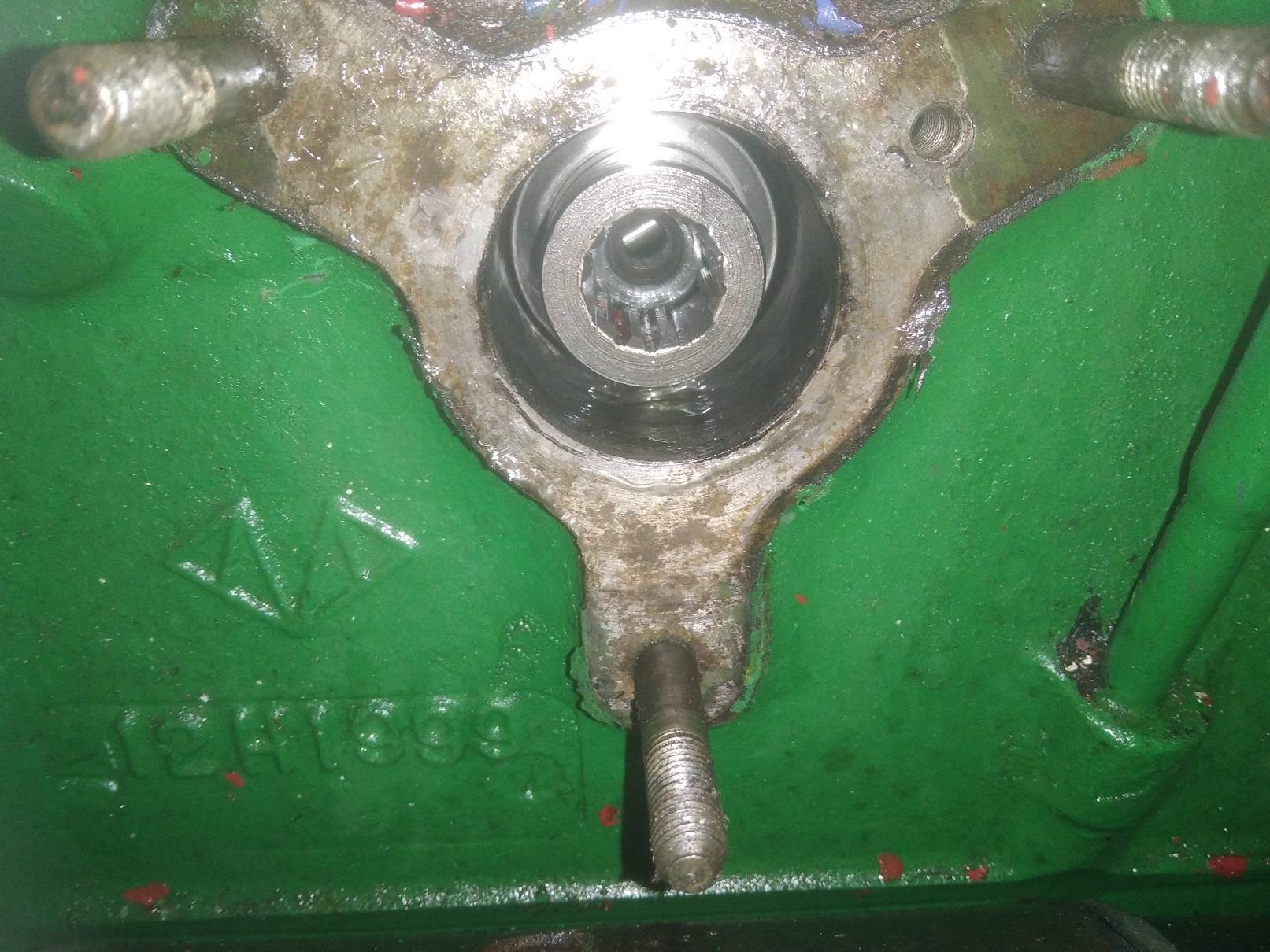
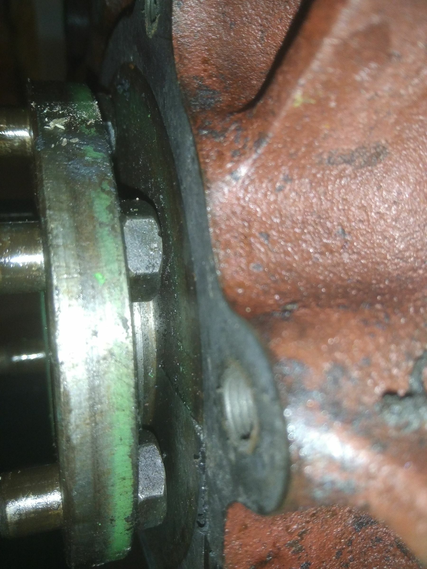
With the crank at a nominal 22 degrees before TDC I removed the injection pump mounting block and moved the skew gear round one notch. Before and after photos here.
I feel it starts better, the issue is where it now starts and then dies, even with full throttle it dies with no smoke implying fuel starvation. After a few seconds it can then be restarted.

-
4 hours ago, john.k said:
If its a "college engine" ,its likely the injector pump has been dismantled by students .....and possible the cam ring has been assembled upside down.......it fits either way............or some other derangement inside the pump.
The old injection pump didn't pump so used another pump. TBH it looked in poor condition where fuel was leaking from the throttle arm. The 'new' pump has been on a working engine.
What do you mean by 'cam ring'?
3 hours ago, Tony Brooks said:My comments.
The manual says that the master spline on the pump drive should end up at 5 o'clock, but yours looks a bit further round clockwise - say closer to 6 o'clock. The skew gear drive teeth are not fine enough to allow this, so it suggests the cam shaft timing may be out for some reason. As the master spline is not that far out, I wonder if the timing chain is very stretched.
Let's tag @Tracy D'arth for her opinion.
If you want exact timing that allows for backlash in the timing train then you do need the tool so you can set the pointer on the top left corner of the mounting plate that you can see in the photo, but I understand many mechanics today do it by ear, by twisting the pump with the engine running.
If the oil jet and filter that lubricates the pump drive skew gears ha snot been regularly cleaned then on an old engine the skew gears could be very badly worn, so a new camshaft is needed.
During the time the engine ran there wasn't any perceptible chain noise. But then I was more concerned over the black smoke filling the area I was working and there was no silencer.
I think the splines/pump run in a an anticlockwise direction and the crank pulley was set close to 22 degrees. If at TDC the key would be closer to 5 o'clock.
I have timed pumps by ear myself and one of the reasons why I replace the solid pipes with hoses, otherwise the 'side' cover gasket invariably leaks from crushing/manipulation of the cork gasket. The force to overcome the spring in the injector pipes is still significant!
A good call about the oil jet and filter. Also an idea to remove the injector mount body and take a look at the pinion. I suppose I can gauge chain stretch from the level of backlash, but don't have any reference to compare that with.
3 hours ago, RLWP said:I have a timing tool, if that helps
Richard
Hi Richard, many thanks for the offer. TBH I was more worried about the position of the skew gear shaft.
-
This engine ran albeit not that well, and I don't want to run it for long without coolant. Given this was a 'training' engine before I purchased it all bets are off regards timing though I doubt the pump drive gear has been removed as it seems captive.
I have timed the crank pulley to be what I believe is 22 degrees before TDC. No 4 valves are tight in this position and rocking around TDC.
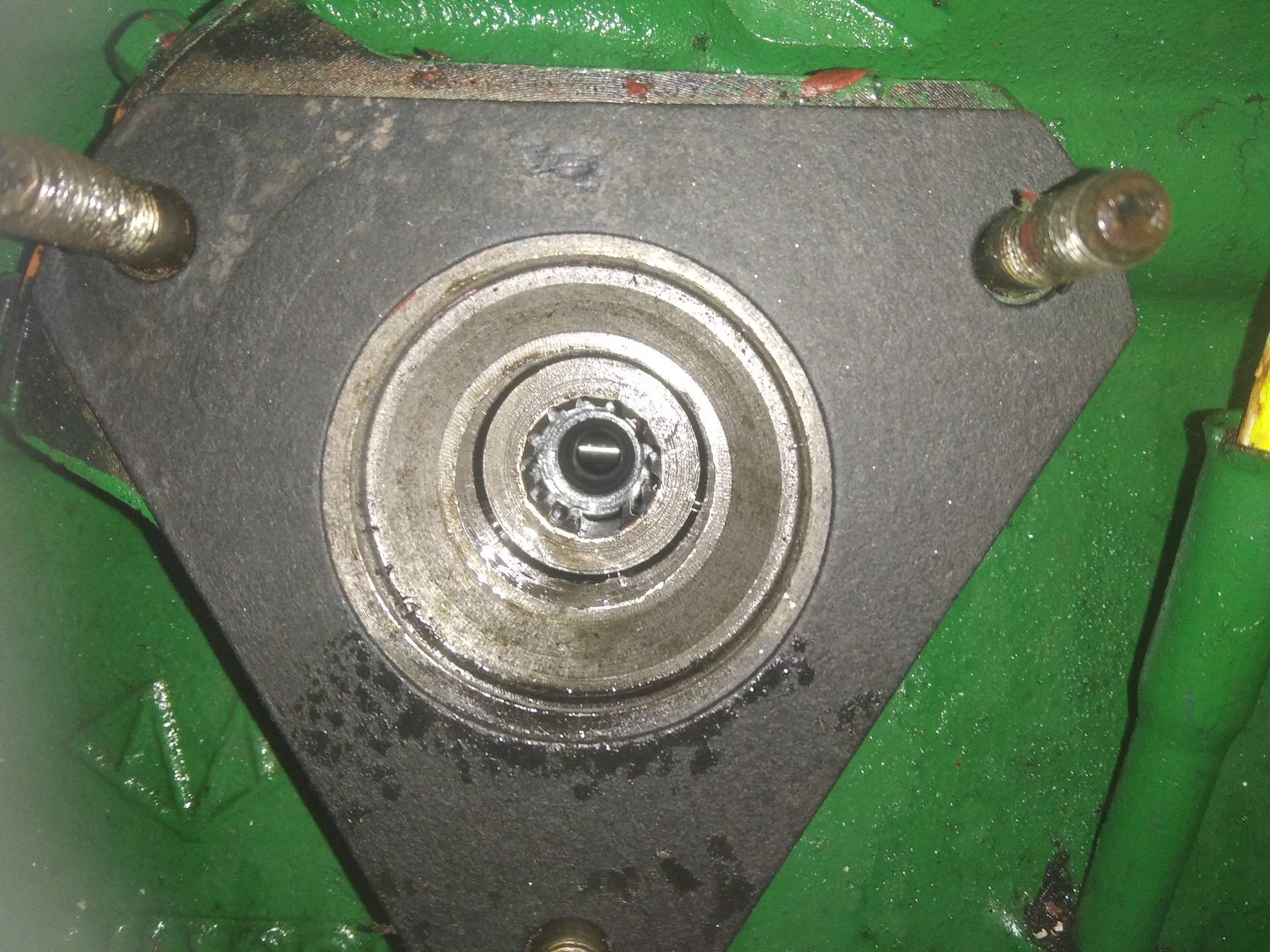
This is a photo of the splines with the pump removed. I don't have a pic or diagram of where the splines should be, the manuals I have at hand have only a reference to a timing tool. Can anyone indicate this is good for correct timing?
-
20 hours ago, Tracy D'arth said:
they are the same on all smaller BMC engines petrol or diesel so an original Mini one is the same for instance.
That's really useful to know. I've only just got some cork ones from Calcutt boats
-
On 25/11/2023 at 18:50, Gilly Milne said:
On a couple of occasions she refused to start, (clunk) not firing until someone from RCR came 'tapped it with hammer' and off she went.
As all the wiring is of an age and somewhat patched in places, I am considering getting her rewired.
Either sticky brushes or solenoid issues. I didn't think disassembly was that difficult and the solenoid, if suspect, can be replaced.
If you're adept with a soldering iron you could disassemble the solenoid and clean up the large copper contacts.
I'm sure there are some YouTube videos on the subject.
I supposed the 'patched' may be a reason to renew your wiring, however if it's isn't broke ................
-
6 minutes ago, LadyG said:
I forgot to mention that I failed the online interrogation as I dont know my GPs practice name, or my NHS number, and when they ask for postcode, is that my current location, my previous GP, the last GP i attended, or where I now intend to get a jab?
If you need a postcode for your present mooring, try using:
Position the arrow to where you are, click on 'here' to convert coordinates it will convert the position under the arrow into coordinates, including a postcode. The postcode database seems is up to date as the building I'm in had its postcode changed a year or two back.
I wouldn't count on any postie delivering, but you never know! Perhaps put canal towpath in the address?
-
I assume this is of the form in the lower image at this URL:

-
On 30/08/2023 at 09:33, Tracy D'arth said:
It must be a very old 1.5D block if it has an oil slinger on the rear. How about a picture?
I have lots of other things to do, hence the time taken to provide a photo. You can see the rear bearing cap join in the photo and I would say there is no room for a seal anyway. Any more detail would require the sump to be removed again as well as the bearing cap.
-
I don't know the terminology so thought I would do some research. I had associated bihex with 12pt spline hence my clarification but more out of ignorance as it's not a term I've heard before. I was aware of a square based fastener called a triple square (XZN) that is also 12 sided.
According to https://en.wikipedia.org/wiki/Socket_wrench
It seems we should clarify by saying "triple square 12-point" or "12-point double hexagon".
-
22 hours ago, Tony Brooks said:
I think a bi-hex one will fit.
I recently used a standard 12 point 1/4" socket rather than the hex variety.
-
50 minutes ago, GBW said:
I have the same interest and found this post by accident.
My reason us that I have a fear of engaging the starter motor while the engine is running.
To preempt the incredulity, I have two identical buttons adjacent to each other, one for start, the other for stop.
I have a remote "start down", "stop up" toggle switch at the helm.
I also have a wife who can't remember which switch to push or toggle. If she pushes "start" when she meant "stop", there will be a horrible noise and the chance of damage.
I am happy with the arrangement, as, in the engine bay, I can select which button by touch and at the helm, "Up" means stop and "down" means start.
All perfectly logical BUT .............!
If I can detect the engine is running, I can disable the circuit to the start solenoid. The oil pressure switch doesn't do it as the starter would cease once the oil pressure rises.
Likewise, the alternator would not serve for the same reason.
Even a pulse detector on the crankshaft would present the same problem.
However, as is often the case, describing the problem to others inspires a solution. A delay in the detection signal produced from any of the above, should solve the problem.
Thanks for the invitation for self reasoning!🙂
In machinery it is custom to have a small green switch for on, typically recessed to stop an inadvertent press, and a dirty great big mushroom stop button that you can't miss.
Perhaps you could apply the same reasoning to switches for stopping and starting your engine?
-
 2
2
-
-
Thanks for the heads up about the strainer. It does get annual oil changes. It has solar panels so the engine isn't run every day.
It was more that the height of the liners that I noticed rather than spacing.
I don't recall any honing marks and all the bores seemed smooth. Once running it does sound pretty good with minimal oil consumption. The sleeves are not new and at least 10 years old. I also don't recall and tell-tale vertical score lines from a broken ring. The clearance around the piston seems about right and minimal lip on the bore. TBH I was taking more interest in swapping heads and getting the engine going due to lack of water on board and overdue a pump-out!
I should have a compression tester somewhere around here. I'm tempted to change the glow plugs as the plastic insulator on some have melted so an opportunity to kill 2 birds with one stone may avail in the near future.
Thanks for all the support.
-
One curious thing is when I took the head off the bores seemed to be sleeved, where the sleeve positions were different on 1, 4 and 2, 3. The pistons were marked std.
In trying to remove the injection pump gear drive oil strainer I destroyed it. I retrieved the remnants out of its bore and the bolt and confident nothing was left behind. The jet is clear. However I can't seem to find where to get one and most parts diagrams I have for this engine omit the feature and what it's called. I would like to replace this.
Finally, although the injectors were working and glow plugs glowing I had to put some oil into the cylinders down the injector bores to actually get it to start.
I am aware this engine after a previous head gasket change (not me) showed very poor compression afterwards, and this also needed oil in the cylinder to seal up the rings in order to get it to start.
-
21 minutes ago, Tracy D'arth said:
I am fairly sure that you will find that the copper washer is not under the top hat but above it.
A sharp chisel and tapping with a light hammer will cut the ring remaining into 2 pieces without damaging the head.
I believe there are two. One which sites under the brim into the head, and another above holding off the injector.
Purchased from Calcutt:
BM12H218 INJECTOR HEAT SHIELD (TOPHAT) BMC 1.5 & 1.8
BM12H219 INJECTOR HEATSHIELD COPPER UNDER WASHER BMC 1.5 &1.8
The under washer is has a slight larger inner and outer diameter and thinner than the one sitting under the injector. I got 2 of everything due to my pessimistic/realistic nature.
-
1
-
-
On 07/08/2023 at 20:05, BEngo said:
Is it possible to get an end mill/ slot drill down the hole? You might need a long series mill or a drill that has been flat bottomed, and it will need to be a decent fit in the hole. A battery drill at low speed or even a tap wrench will drive it. If you are lucky it will grab on the remaining 'brim' and loosen it.
Alternatively a good sharp tap reseating tool of the right diameter should do it.
N
I have good access to a milling machine and a number of cutters. I have some step blocks so with shims I should be able to get the injector hole pretty much vertical. I only need to cut down to the copper washer so minimal risk to the head. I f I use a smaller cutter I should be able to cut just a side of the brim that should help loosen it's grip on the injector bore. My main concern is how hard the material is. The fact I could easily tap a M16 hole suggests it should be ok.
On 07/08/2023 at 19:00, Tracy D'arth said:I meant before you ripped the middle out! I would take a sharp chisel to that remaining ring and chop it into two, slightly marking the head will not matter.
Yes, in hindsight that would have been an idea but TBH I was trying to avoid removing the head.
The fact I left the brim behind with a straight pull makes me wonder if sharp taps from below with the swirl chamber removed would have ended up the same result?
I have hit the top-hap from above with a metal screwdriver and I'm not convinced I'm doing very much. I'm also wary or hitting it any harder and breaking the head.
-
Unfortunately I can't attack it from below. The central part has come through leaving a small annular rim that is inline with the head casting and leaving no ledge to knock it out with.
-
I'm wondering if it's the original, so 35 years old. Thankfully I have a spare head that came from a seized engine.
When I've got time I can use a miller to cut the the brim out of the head.
I was initially feeling very pleased with myself as it seemed to come out smoothly! It was a good straight pull. I took the injector studs out and used a 5mm plate as per photo.
It's funny how experiences can vary, but I've not heard of this happening to anyone.
-
An existing top-hat had suffered corrosion and wouldn't seal with the correct copper washer. So I decided to replace it. The saga started in the thread, "Changing injectors on a 1500"
I recall in this forum how easy they were to get out and how they might even come out with the injector.
So, I got an M8 tap and screwed this into the top-hat and there was minimal purchase, I had an M9 tap which I screwed in but couldn't really give it a good pull. M9 bolts aren't very common.
Next, an M10 tap, some studding and a nut and the thread pulled through the top-hat making a mess of the studding.
Next, an M12 tap, some studding and a nut and the thread pulled through the top-hat also making a mess of the studding.
Last ditch chance and no return using an M16 tap that in the top tat, where it made a thread from top to bottom inside the top-hat. Using a bolt and nut I wound the top-hat out. Sadly the brim was left behind.
So it's head off and swap for another. I expected its removal would be so much simpler!
-
I presume a simple buzzer arrangement is an issue where it sounds when you are in the glow-plug heat position. Otherwise as already said, it is a means to test the buzzer.
I can think of two solutions.
1) Connect the buzzer to the ignition warning light aka Ind terminal so the buzzer is fed from the excitation side and only live when the alternator is running.
2) Put a relay in parallel with the charging warning lamp and use n/c contacts to fee the buzzer.
The chances of two faults, the alternator failing as well as losing oil pressure is pretty remote, without someone noticing. Plus the oil lamp would still work as intended. I suppose a variation is to use the glow plug feed for the relay, that might discourage too short a heat time.
-
23 hours ago, Tracy D'arth said:
Read full at top mark on the stick when screwed in, read full at bottom mark when just dropped in.
Thanks, so it's overfull by a mark. I would imagine it's not critical.
-
2 hours ago, cuthound said:
Some years ago we had a really load clanging noise when we engaged gear on our first shareboat.
It turned out to be a Sea Searcher magnet which had attached itself to the bottom of the boat and its attached rope had wrapped itself around the prop.
Fingers crossed it's something similar. I've come to the conclusion to leave all well alone. The noise gave did give me that sinking feeling!
In the mean time I checked the gearbox oil, and it is immaculately clean. Possibly slightly overfilled, depending on how you read the stick.
Many thanks for all the replies.
-
2 hours ago, Tracy D'arth said:
Or a bunch of wire/rope on the prop...................
The video won't run for me but it looks like a PRM 160/260/280 gearbox in there with an Aquadrive/Python coupling. I would be amazed if it was the gearbox, they are very solid and regarded usually as bomb proof.
Have you tried a listening stick to narrow down the source of the noise?
The shaft still spins in neutral without the accompany noise, so I dismissed the possibility of any issues with the prop, prop bearing or the coupling. Yes the gearbox is a PRM 160. My next job is to determine the state of the oil in the gearbox. The dipstick bolt head has been chewed and I need to take an 18mm 6 sided socket to undo it.
I'm still concerned over the drive plate, even though the more serious clanging noise has gone for now.
Many thanks for the replies.
-
Today the clanging noise has disappeared but the gearbox is still noisy.
All visible bolts and mounts seemed ok.
I include a 1 minute or so video of the engine on tick over to start with with forward initially engaged and then disengaging etc.
https://drive.google.com/file/d/1RWgbDWMImfKn19E1L0N8rUghyH4mBCgi/view?usp=sharing
What is notable if that the noise only occurs when the gearbox is engaged in either forward or reverse. Since the output shaft to prop rotates quietly in neutral this only leaves the gearbox.
-
This is BMC 1500 and a PRM gearbox. I assume it's all original, late 1980s.
This has only just started. Quiet in neutral but noisy when in gear at low revs. Quiet again with modest power. Everything performs as one might expect.
I'm assuming this is a drive plate issue? I would be grateful for a steer?
1500 Injection pump timing
in BMC
Posted
Thanks for your vote of confidence. I don't think the issue is air? If I undo the banjo I get fuel but will check. It's a new filter. My thoughts were the screen filter in the pump.
If it stops, the pressure seems to "build up" sufficiently for a restart.