David Mutch
-
Posts
201 -
Joined
-
Last visited
Content Type
Profiles
Forums
Events
Gallery
Blogs
Store
Everything posted by David Mutch
-

Who built our boat? Listed as a Rugby boat
David Mutch replied to SFen's topic in History & Heritage
For the curious. Colecraft have had a look and say that she's not one of theirs. So the mystery deepens! -
Who built our boat? Listed as a Rugby boat
David Mutch replied to SFen's topic in History & Heritage
Thanks. To clarify, paperwork states built by Rugby Boat Builders 🙂 -
Who built our boat? Listed as a Rugby boat
David Mutch replied to SFen's topic in History & Heritage
This seems like a very good idea to me! Thanks. Had a look at your blog and she certainly bears at least a passing resemblance to Water Snail. I think a quick call with Colecraft is my next move now 🙂 -
Who built our boat? Listed as a Rugby boat
David Mutch replied to SFen's topic in History & Heritage
That is certainly a feature of ours! -
Who built our boat? Listed as a Rugby boat
David Mutch replied to SFen's topic in History & Heritage
I think this is probably about as close to that angle as I have.
-
Who built our boat? Listed as a Rugby boat
David Mutch replied to SFen's topic in History & Heritage
Thanks. I suspect the name of our boat has been changed at least once. People often remark on the shape of our hull, but we certainly have a steel cabin 🙂 -
Who built our boat? Listed as a Rugby boat
David Mutch replied to SFen's topic in History & Heritage
We had no inkling that she might have been a Colecraft until a number of people suggested it to us. All we knew was that she was registered as built by 'Rugby Boat Builders ', but as far as we can tell this is not in fact a boat builder, but a boat fitter (and, it's been suggested to us by someone in the know about historic boats in that area of the world, a hire boat company). We're really interested to know who/what 'Rugby Boat Builders' are/were and then hopefully to find out a bit more about who built our hull 🙂 I don't think the CRT licence says anything about the builder. That is the builder listed on Canalplan, but also on paperwork we have for the boat going back to not long after she was built. Could be wrong, but I've not seen anything to the contrary 🙂 Thanks! That's very interesting. I can certainly see a family resemblance with Jabez Bunting (or at least I fancy I can). The front door to the side in particular. Speedwell, not so much 🙂 -
Who built our boat? Listed as a Rugby boat
David Mutch replied to SFen's topic in History & Heritage
Thanks. We are, but as I say, the only one we've seen exactly the same the owner just said it was 'Stephen Goldsborough', and it seems likely they were no more a boat builder than were Rugby Boat Builders! But as you say, sooner or later we'll find another 🙂 -
Who built our boat? Listed as a Rugby boat
David Mutch replied to SFen's topic in History & Heritage
Yes, the upsweep at the front is very distinctive. The most similar boats we're seeing a lot at the moment of are Liverpool Boats, but that may just be a function of where we are in the world at present! The very narrow rear deck seems unlike most boats we see around too. -
Who built our boat? Listed as a Rugby boat
David Mutch replied to SFen's topic in History & Heritage
The problem seems to be that we've met roughly equal numbers of folk who swear blind she is and who swear blind she isn't a Colecraft. It may be that she was built to a special design, as you say. We don't really mind who built her, but we'd like to know. Saying that, though, nobody has ever suggested anything other than Colecraft; just that she isn't a Colecraft! 🙂 -
Who built our boat? Listed as a Rugby boat
David Mutch replied to SFen's topic in History & Heritage
Thanks. I was having trouble uploading, so the link was easier. Can provide more pictures if necessary! 🙂 -
Who built our boat? Listed as a Rugby boat
David Mutch replied to SFen's topic in History & Heritage
I suspect you're right there. I'm wondering if Colecraft may have built some of those shells?! Would there be any identifying marks of the builder? I've never spotted anything, but some kind of maker's mark hidden in some nook of the engine bay, perhaps? 🙂 -
Who built our boat? Listed as a Rugby boat
David Mutch replied to SFen's topic in History & Heritage
Thanks @nicknorman. May have cross-posted there. Please see link in my post above for some photos of the boat in question 🙂 -
Who built our boat? Listed as a Rugby boat
David Mutch replied to SFen's topic in History & Heritage
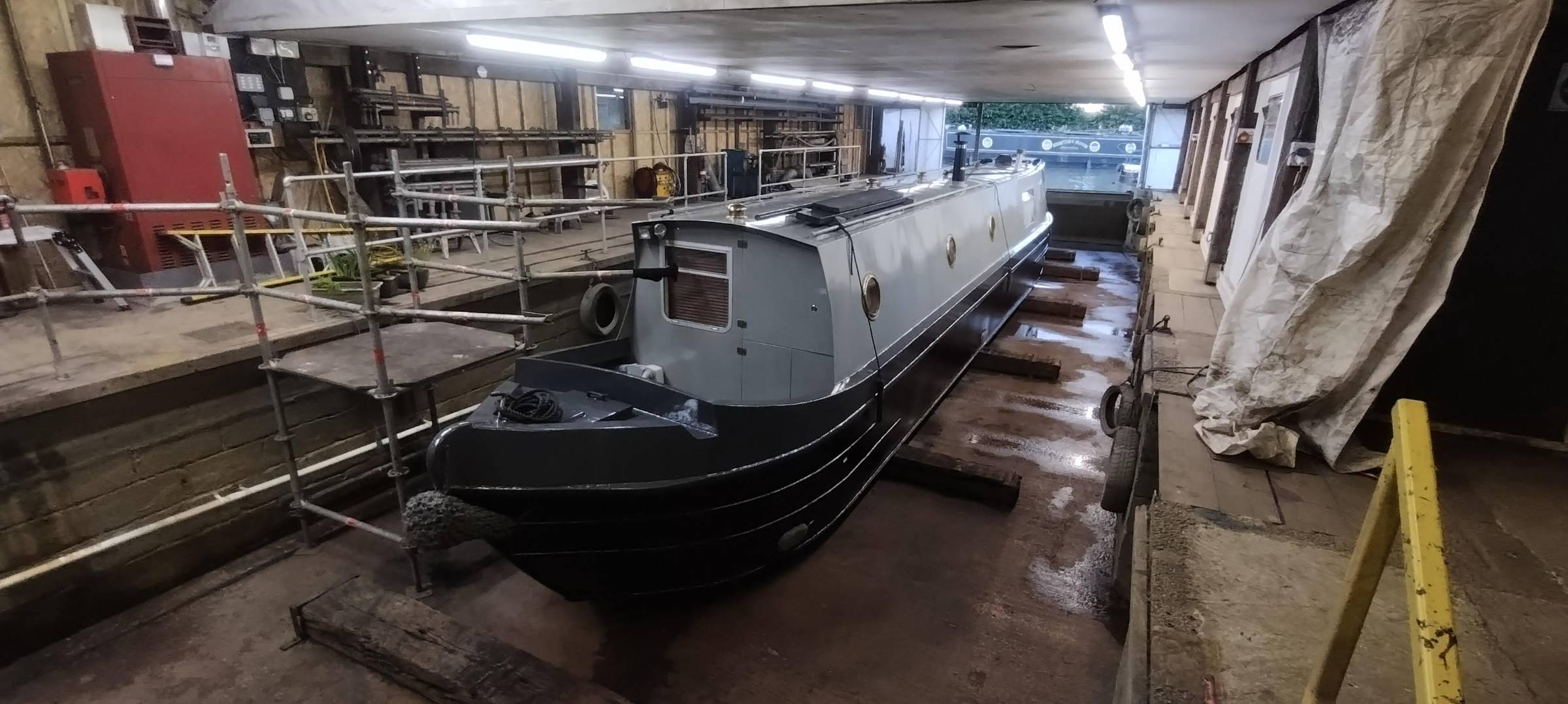
Hi. Here's some photos of the boat in question (also my boat - am @SFen's lesser half). Nice to know where Rugby Boats were (we were in Hillmorton not so long ago), but what we're not clear on is what Rugby Boat Builders were. A hire company? A boat fitter? A number of people have told us that Colecraft built hulls for them, and have suggested that ours might be built by Colecraft. But that just makes the name 'Rugby Boat Builders' a little mysterious, as it seems the one thing they didn't do was build boats! We're also not sure how to identify one. Although lots of people have asked if we're a Colecraft, I can't see a lot of similarities with other Colecraft that have been identified to us, and some Colecraft owners we've spoken to swear blind that ours isn't a Colecraft. We did meet one boat that was the spitting image of ours, and were told that it was built by 'Stephen Goldsborough'. I can only assume that there is a connection between this boat builder and Colecraft/Rugby Boats. Any more details on the history and identifying features would be greatly appreciated 🙂 -
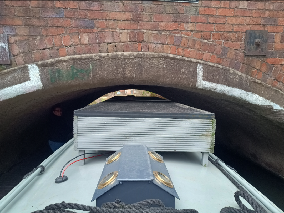
For those who are interested, we got through Brettell Lane. I measured clearance from the water to the channel marker on the towpath side of the bridge at ~78" (6'6"), although the inside of the tunnel isn't at all uniform, so it could vary a few inches in either direction. The water level couldn't have been any higher without going over the towpath, so I don't think it gets tighter than that. Had to take the chimney off to get through, but thankfully the roof boxes, at ~76", got through in situ. There's been a couple on the Staffs and Worcs where the chimney had to come off, but nothing quite as tight as Brettell lane.
-
A 50' narrowboat
-
Thanks. That's in one way reassuring and in another worrying, as now it seems I can't rely on C&RT's official dimensions! For example, they quote 6 foot headroom for the Stourbridge canal too, and don't give any specific pinch points, although I believe there is one at Brettell Lane bridge. Thanks. That's worth being aware of. Nearly lost a chimney a few times that way!
-
Hi all. The official C&RT dimensions for the Staffs & Worcs says it has a maximum headroom of 6 feet. I've searched all over, but can't find any information about where the pinch points might be, or even any mention of any particularly low bridges, etc. Anyone out there with local knowledge? Thanks
-
Thanks. I'll have a go and report back 🙂 Thanks. Not leaking round the bolts so far as I can see. Looks like it's leaking at the joint. I'm hoping a new coating of RTV will fix the problem (at least temporarily)
-
D'Oh! I'm being a little slow this morning. My 1/4" fits. Was assuming it had to be a 1/2"! Thanks!
-
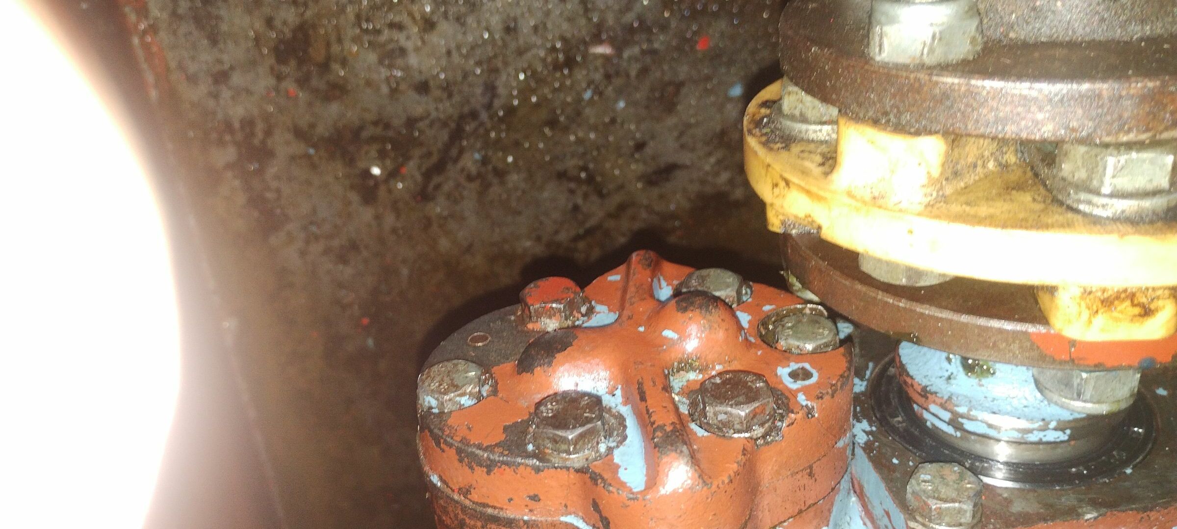
D'Oh! That makes a lot more sense! 🤭 It's obviously had some sort of sealant on it before. I didn't remove the pump to do the rear oil seal. I suspect the leak is just showing up now because the box finally has the right amount of oil in it! What I can't work out is how I'm supposed to get a spanner/socket on the two recessed bolts (pic attached). What am I missing?
-
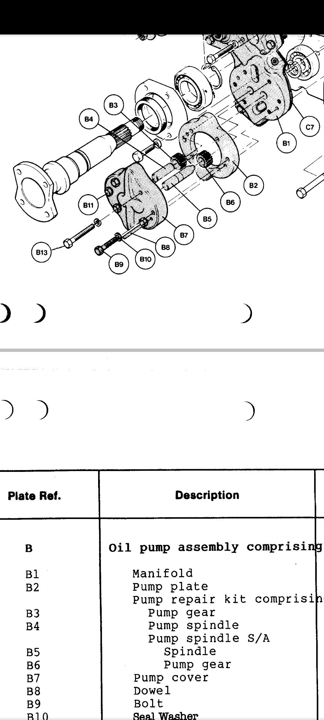
Hi all. Well, thanks to your help, I think I've got it licked. It was a bit more involved than I had imagined, in particular removal and refitting of the rear bearing. The output shaft had a visible score line where the seal sat, but you couldn't actually feel it with a nail. It was also slightly corroded, but not where the seal sits. Managed to clean it up ok with some wet and dry and very careful use of a Dremel. The new seal is of a different design and so naturally sits in a different spot, so decided there was no need to sleeve. So far no leaks, but time will tell. I say no leaks, but actually now there's a different leak, coming from between B2 and B1 on the attached. Am I right in thinking that this just houses a repair kit for the oil pump, and can be removed and resealed independently of the rest of the oil pump assembly? Thanks 🙂
-
Doesn't look like it's necessary to disconnect the water side of the oil cooler in my case, so hopefully won't be a problem, but thanks for the heads up 🙂
-
Thanks Tony!
-
Any reason the engine can't be run with the gearbox off? (Just in case I can't get it all back together in a day and need to charge the batteries)