


Tony Brooks
-
Posts
30,074 -
Joined
-
Last visited
-
Days Won
139
Content Type
Profiles
Forums
Events
Gallery
Blogs
Store
Posts posted by Tony Brooks
-
-
Just now, MtB said:
BR is answering a comment about a different engine, where the author is describing a fault he'd suffered that sounded a bit like the OP's problem initially.
I see.
4 minutes ago, MtB said:In fact looking at the first photo, the prop shaft flange looks noticeably to the left of the centreline of the gearbox output shaft. Or it might be an optical illusion in the photo.
Certainly, it looks to me as if the back face of the aluminium housing and the face of the clamp ring around the shaft are out of angular alignment - not parallel - but that may be camera dstortion.
-
1 minute ago, MtB said:
With an engine on rubber mounts I like to see a pair of UJs to take up engine movement, and a sliding spline with a thrust bearing such as a Python Drive or similar.
or Aquadrive, I totally agree, but that would probably mean a gas axe and rewelding the carries for the thrust bearing further back towards the prop - if there is space.
As there is a thrust bearing in place there might be space for a double UJ, if any can be found.
I wonder if the noise is actually the thrust bearing breaking up - listening stick time, but not on the flexi

-
14 minutes ago, blackrose said:
Whoever fitted the bolts from the gearbox case to the bell housing was a bellend. 🔔
Please elucidate, I have failed to spot any gearbox case to bell housing bolts in the OP's photos.
-
51 minutes ago, Rich m said:
That is nose bleed money this is my engine mounts can you suggest a work around
Yes, as others have alluded to, check both the radial and angular engine to shaft alignment and correct as required. IF the alignment is correct then a simple R&D "flexible" coupling may be good enough, but they take up far less space that what you have, so that is another problem.
If the alignment is out, then the flexing and vibrations are likely to cause any flexible coupling to fail well before its time.
If you find out what has failed, then spare parts might be available at less cost.
-
2 minutes ago, magpie patrick said:
I have a Viking 23 - there is effectively no insulation. When I've been on in winter I've found it's the condensation that's the issue not the temperature.
Insulating the ceiling would be relatively easy, the walls less so as there is fit-out in the way.
Juno has windows the full length of both sides and at the front, it's wraparound in effect. Not sure how I'd double glaze it either as cabin side is no thicker than the windows
Double-sided sticky foam tape and clear plastic film. I am not sure if it is still available, but there is/was heat shrink plastic film that you can take the ripples out with a hair dryer. The wrapround ones would be difficult, but not impossible, as long as you can develop the shape for cutting out.
-
1 hour ago, nicjo said:
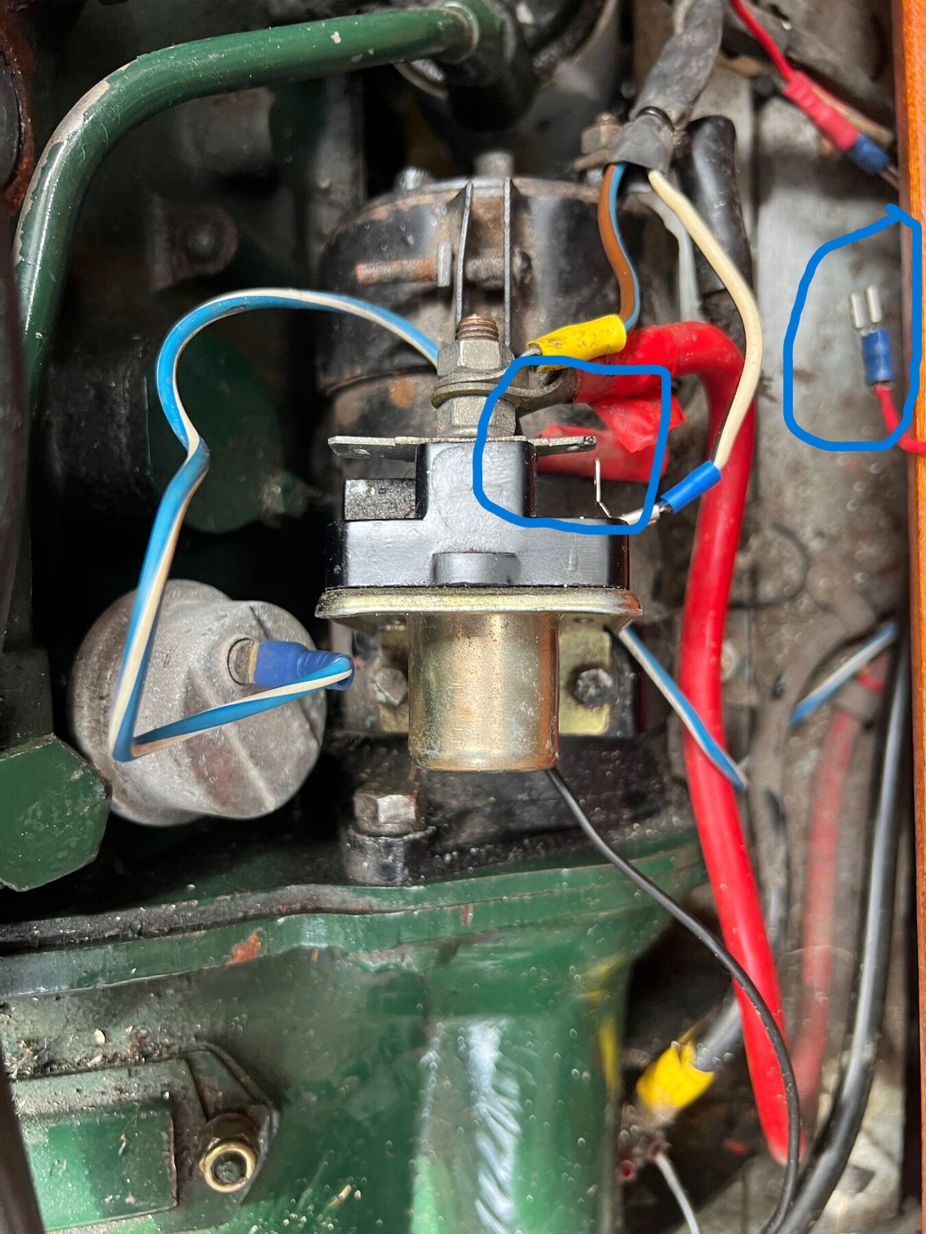
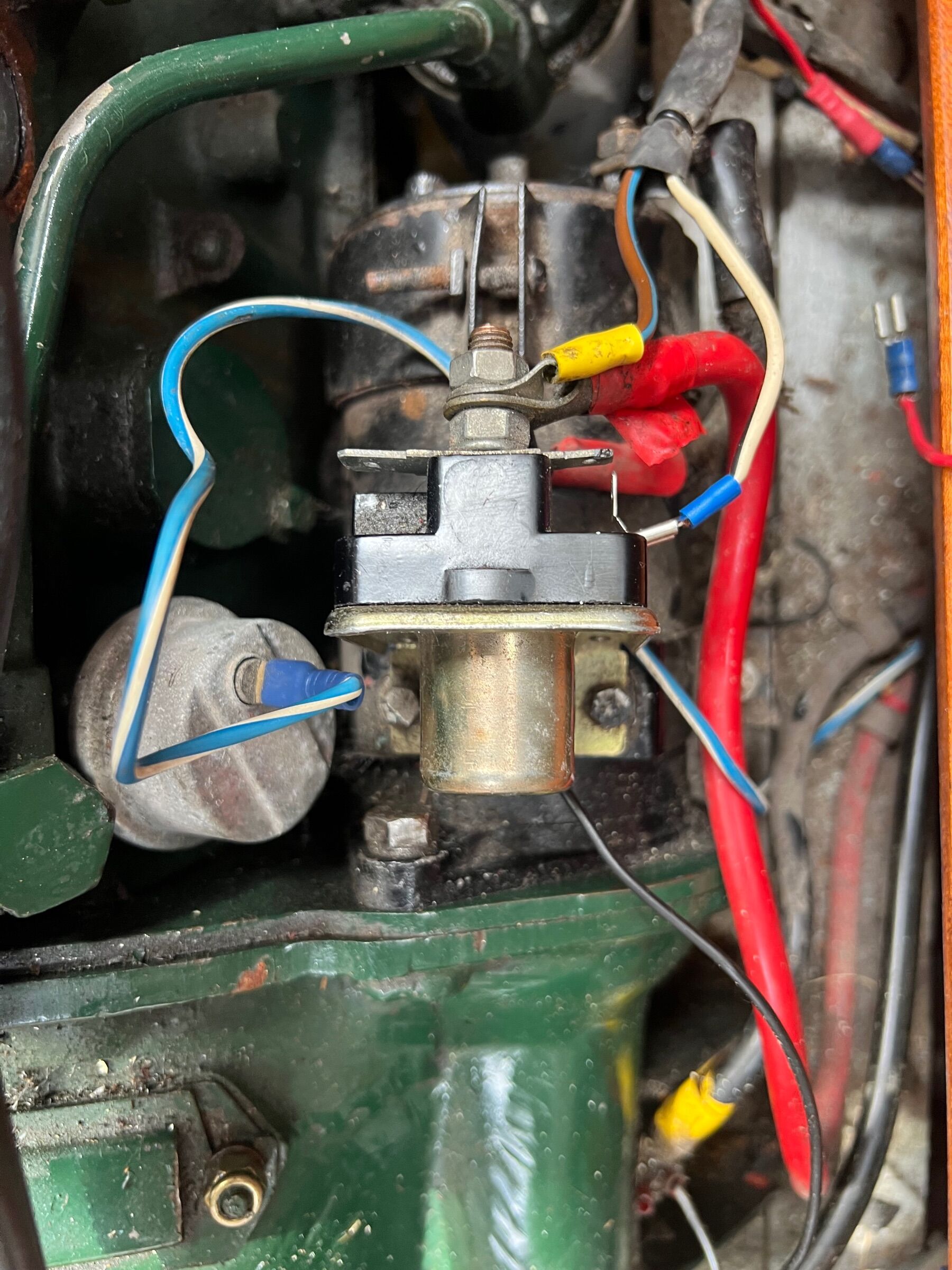
Well spotted Sir !! yes thats an old photo i had of the solenoid to show you the set up .. The white wire is the switch to the sol from the ignition. The other red from memory is the feed up to the coil and was disconnected whilst i was working on it last year.. I think the piggy back was because i ran out of normal spades !! That just reminded me to order some !!
White wire Now you say that, and I have had a closer look, of course it is, my mistake. I would bend the blade on that piggyback down so it is well away from the live battery feed, even though it is between the two large terminus.
Red wire. Unless the previous owner pulled it off each time he stopped the engine, the red wire would have put 12V on the coil all the time and on contact set distributors that often resulted in the coil burning out because they are designed for the 12V to be pulsed. However, I am not sure if the same would apply with the electronic ignition.
-
5 minutes ago, Alan de Enfield said:
I don't suppose that those two disconnected wires have anything to do with it - do they ?

White on a boat of that age and wired to the UK automotive colours would normally be unfused, ignition controlled, but it has come off what, on those solenoids, would be the main battery feed. This suggests to me that wire was used as a feed for something, but I don't know what it would have been. There is no way I can even guess at what the red wire was/is for. If it is long enough, it might have been attached to the piggyback connector on the white wire, so possibly another feed to something.
I now think the ignition wiring is OK from what the OP has told us.
27 minutes ago, nicjo said:
Happy to say that solenoid is not equipped to supply a ballast resistor system, so perfectly standard for that engine, apart form it being the modern design.
-
2 minutes ago, ditchcrawler said:
If I remember I screw mine until its tight once I stop for the day , I am much better now but in the past I often forgot to do it. Also our prop is reasonably slow rotating by modern standards, probably about 450 RPM occasionally going up to 550 RPM. Looking at Gybe Ho prop size he will probably be the same.
That is my procedure as well, and just as it starts to stiffen I can see grease or water just starting to ooze from between the shaft and pusher. In my case I tended to cruise at around 1300 to 1400 RPM and on the big rivers at around 3000 RPM so that is about 500 rpm and 1000 RPM shaft speed.
I think that we both have Aquadrives, so a more typical boat would probably need far more adjustment and greasing than ours.
-
I think the proportion of single glazed window area to cabin side may be greater than on many narrowboats, so again, more heat loss or DIY double glazing.
-
21 minutes ago, nicjo said:
Ok so Tony prob going to tell me off but I bit bullet and ordered new electronic distributor and performance coil after speaking to the guy at Morris Minor classic parts.. Was only £90 and that should eliminate the spark / coil side of things.. Then ive got some new flex marine fuel hose to connect to carb and avoid passing a few mm from the side valve / heat of the engine.. Also going to order a smaller main from a 85 to a 75 and try that if the plugs are still looking oily. Plus got some heat shield to install and direct heat from engine on carb and order from Amal a heat gasket for carb to engine (think 3/5 mm) .. Will keep you all up to date on any progress when the parts arrive.. if nothing works after all that its got to be fuel input? Then i may go and install the fuel pump and see if the mech one is pushing in to much ? Thank so far to all the input guys...
Your money, so as long as you think getting a whole new electronic ignition kit is worth it, then fine. I just find it an anathema to spend "customers" money before a credible diagnosis.
For information, those plugs did not look oily to me, they looked sooty, and that is indicative of a rich mixture, so maybe the jets will sort it.
-
42 minutes ago, Gybe Ho said:
Thanks. This suggests it is possible to get through half the adjustment range over a 2 or 3 year period between haulouts. All depending on cumulative prop revolutions and not overtightening the pusher.
If the shaft is correctly aligned, does not move fore and aft under prop thrust, and is adequately isolated from engine radial movement then 10 years plus between adjustment is possible, but it does need something like an Aquadrive coupling. That means the boat will probably be sold on before it needs repacking. This is where traditional solid mounted engines win out over flexibly mounted ones.
-
5 minutes ago, nicjo said:
you think replacing the distributor with a points and condenser system rather than electric sensor is the way to go /
NO, we still have not established if it is a fuel or ignition fault. I don't know how much a set of pints and condenser would cost, but I expect £10 would cover it, that would rule out a problem with the electronic ignition module, and if it worked, the coil as well. But there are still the cause of those very black plugs to deal with.
-
21 minutes ago, Gybe Ho said:
There must be some ambiguity in how I phrased the question. Repacking the pusher is a job that I hope can be done as needed post launch. The task I am thinking about, that probably has another description, is repacking the internals of the stern gland at the hull exit. My earlier yachts had lengths of square wadding wrapped around the prop in side the gland. As the plunger pushes in grease the grease is forced around the wadding and propshaft.
My most recent yachts had s-drive propulsion hence no conventional propshaft. Maybe stern tube technology has moved on and/or a different design is used on narrowboats.
Repacking the stern gland is where you remove the old packing (presumably what you call square wadding) rings and repack with new, as you describe, with the joints at 120 degree intervals. That is exactly what KIB was describing. The pusher, on many narrowboats, is the thing that pushed on you "wadding". What you call repacking the pusher, I have no idea, unless you are talking about refilling the greaser.
-
 1
1
-
-
Just now, Kingdom Isambard Brunel said:
I cannot recognise that ignition system. There is no magnet ring on the distributor cam to trigger the sensor. I am at a loss how it works.
I suspect it is an inductive sensor sensing the peaks of the cams lobes, but then where does it get the power to switch the coil on and off, presumably by a transistor in the black housing. I can't see how "bleeding" some of the pulsing coil primary current off to power the electronics would be particularly easy, but who knows with aftermarket kit.
2 minutes ago, nicjo said:the first top left red wire on + on the coil is the feed from the starter switch which gives me 12v when turn it on when its off the coil.. This is connected to the + on coil which then on same + feeds into the red on the distributor.. The - on the coil blue wire feeds down to the black going into the distributor.. sorry if im not making any sense !
Right, so the "second" red wire is feeing the electronic ignition. That makes some kind of sense. The black box inside the distributor is just an electronic switch instead of contact points. Both the coil circuit and the electronic part goes to negative via the distributor baseplate.
One good thing is that without a vacuum advance retard mechanism, at least we don't have to consider a bad contact between the "contact" plate and distributor body.
-
7 minutes ago, nicjo said:
arh this i know the red cable goes to the starter solenoid as i replaced that last week too!! and a thick black cable earth straps to the engine !!👌 and no external box to distributor
Right, although the part number says differently, that wiring configuration strongly suggest that at some point this engine was converted to ballast resistor ignition, but I can't be sure until I see a photo of the solenoid and connections. Then at a later day electronic ignition was fitted but the solenoid wire that provided 12V to a 10V (KIB say 9V) coil only during cranking (to give a nice fat spark) was never removed. However, for now, I can't recommend that you remove it and see what happens, but I don't think doing so will cause any damage.
-
6 minutes ago, nicjo said:
ll I know is the live from turning the ignition key on is 12V going to the +on the coil which then feeds from other side of the coil+ to the dizzy. The -on the coil goes black into the dizzy.. thats where my knowledge runs out!!
Ignition switch > coil > contacts in the distributor is the normal way of wiring, but as electronic ignition system usually need a 12V feed of their own to work you have an extra red wire on the coil to provide this feed, BUT the second red wire on the coil does not seem to go to the modal in the distributor (only two wires there, red & black with black turning to blue at a connector block). So ether that second red wire is running to an external modal (or should be) or it is for something else, but I can't think what on that engine.
You need to trace that second red wire on the coil.
For the cost, I still think fitting a condenser/capacitor and set of points to the distributor would totally rule out the electronic ignition.
-
10 minutes ago, nicjo said:
oh Christ your all getting a bit techy elecy for me.. i struggle with 3 pin plugs.. will have to consult my mate tomorrow to give me direction for some of your questions ?
The answer to Bod's question, based on the photos is "no there is no condenser or contacts fitted", and as far as I can tell there is no electronic box external to the distributor.
My question about positive or negative earth is answered by telling us which battery terminal connects to the starter solenoid - it will be a thick cable. Alternatively, which battery terminal is connected to the metal of the engine.
-
1 hour ago, David Mack said:
Surely under GDPR they should delete your information if you unsubscribe. I would be minded to complain to their Data Controller and ask to see the evidence that you have consented to receive mailshots.
I tried this, except I went to the Data Commissioner, it is how I know name and address is not considered personal information. My guess is that the
businesscharity would claim that the initial donation had set up a relationship with them.How many times have you seen a "do not contact me" box on either a business or charity web form? Worse still, the web forms usually give no facility to add that.
-
That coil seems to be an aftermarket standard 12V coil marketed as a coil for enthusiasts, so apart from the fact it seems not to be oil filled, it should be fine, and the fact you still have a spark as soon as it stops rather rules out an ignition fault.
Another off the wall consideration. Is the engine positive or negative earth? Around that build time both were in fairly common use and the coils terminals were often SW & CB. but they were positive earth coils and if you get the connections wrong you materially degrade the power of the spark. So check the wire from the ignition switch is on the correct side. + for negative earth and - for positive earth (I think).
-
1
-
-
10 minutes ago, Kingdom Isambard Brunel said:
Most BMC engines of this period including Minis had heat spacers on the fuel pumps. They were about 4mm thick and also dropped the fuel delivery per stroke slightly. I cannot see that this can be the OPs problem as the engine is not in a car and he has tried an electric pump too.
So called cold start ballasted coils will burn out if run at 12V+ as they are actually 9V coils, I cannot understand one going on and off with time connected.
This engine has been fitted with transistorised ignition, It has a magnetic pickup in the distributor. So I would suggest that the electronics are being affected by heat and switching off. Where is the electronic module located?
It looks like inside the distributor, but that might just be the sensor, but it looks a bit big for that.
I said near to the start that it sounded like something failing with heat in the ignition system. I think I would be worth fitting a set of points and condenser to see how it goes then.
-
Long time ago, but I think the 1500C BMC petrol engine used plastic heat insulators between the lift pump and block, but I don't think that you can just add one because it affects the relative position of the lift pump arm and eccentric.
I also think they had them between carburettor and manifold, but that was with Zenith down drafts.
Can you clip a spare spark plug to the engine so that when it stops, you just fit a lead from one plug t it and test for sparks.
Another long shot, have you checked the coil is NOT one for a ballast resistor setup. If it is, and you are feeding it 12V+ direct from the battery, the coil will overheat, and I have a hazy memory of that causing random engine stopping.
-
Deleted as the post this responded two has been edited
-
On water cooled boats, I am sure it is just for combustion air, but why they put them on the outside of the hull I have no idea apart from ease. It must be possible to put them on the inside, as on my cruiser stern. Or better still in the well deck with vents through the rear bulkhead, so the engine draws air through the bilge - not much good if you have filled the bilge with insulation above the ballast.
-
1
-
-
May be use a hammer and dolly to straighten any minor bends and possibly angle grind rough nicks, otherwise nothing unless it is singing. In that case, one would grind anti-singing edges
Advise
in Boat Building & Maintenance
Posted
On a 15" laptop, perhaps the angle of that "pipe" across the area in question is confusing my eyes. Certainly worth Rich M checking in real life.