MixingWizzard
-
Posts
24 -
Joined
-
Last visited
MixingWizzard's Achievements
")
Explorer (2/12)
4
Reputation
-
Ah, that's really helpful - I have almost exactly the same setup as you, but I only have two fairly small radiators in the bedroom end. My stove is tiny and fitted at the bow end so it doesn't really reach the stern. I'm mainly hoping to at least defrost the bedroom before I get up! I'm not aboard for a few days but yes, I coupled the flow and return pipes where the LPG boiler was. It went: Calorifier in engine bay > radiator > radiator > LPG boiler > return. I'm assuming it was installed like that to avoid long gas pipes and to avoid having gas anywhere near the engine. I'll be using the same pipes into the Calorifier but in a different location - the main aim was to free up some space by moving it into the engine bay. The engine heats the Calorifier via the skin tank on a separate coil via the engine coolant pump - there is no control for this as far as I can tell.
-
Excellent, so it looks like all I need is a header tank (I've picked up the 5L one). Above the Calorifier might be tricky as it's pretty high up in the engine bay but I'm sure I'll figure something out. I wonder what will happen when the engine heats the Calorifier but the diesel heater/pump isn't running? Might it be worth wiring the pump to a separate switch so I can run the rads on the engine as well?
-
Hello all, I'm looking for a bit of advice on my heating setup. Our boat had a very old LPG heater "midship" which I removed in the process of renovating the bathroom. I'm planning on replacing it with a diesel heater in the engine bay, however I'm a bit confused as to how to hook up the radiators. Currently the two radiators are on the second coil of a Calorifier (the other being the engine). Where I've removed the LPG heater I have created a loop. My plan was to run the diesel heater on this coil to heat the radiators but also give me some hot water to the taps (ideally with the option of closing off the radiators during summer). I'm assuming I'm going to need some kind of coolant reservoir and possibly a bigger pump than the diesel heater comes with (which would normally just be feeding a coil). However, my YouTube plumbing skills have failed me as it seems to be a fairly non-standard situation (I'm not really sure what to search for!). If anyone can point me in the right direction that would be much appreciated. Many thanks
-
Mounting Low Voltage Electrical Boxes
MixingWizzard replied to MixingWizzard's topic in Boat Building & Maintenance
I should note that the electrical items I'm installing are actually going below this cupboard (out in the open), the cupboard picture was more for fun. I've put the fan directly behind the DC-DC charger - it's a Victron Orion 30a. Apparently it's normal for them to get that hot but it still worries me. At least I'll save on heating. It's just attached to a bit of builders band for now but perhaps z-brackets are the way to go rather than building a whole panel for them. If I ever get around to it I'd like to remove the whole lot and start again with a bigger cupboard. It has clearly been added to over the years and has started to spread around the whole stern wall which is a bit of an eyesore. -
Mounting Low Voltage Electrical Boxes
MixingWizzard replied to MixingWizzard's topic in Boat Building & Maintenance
I am now! 😁 -
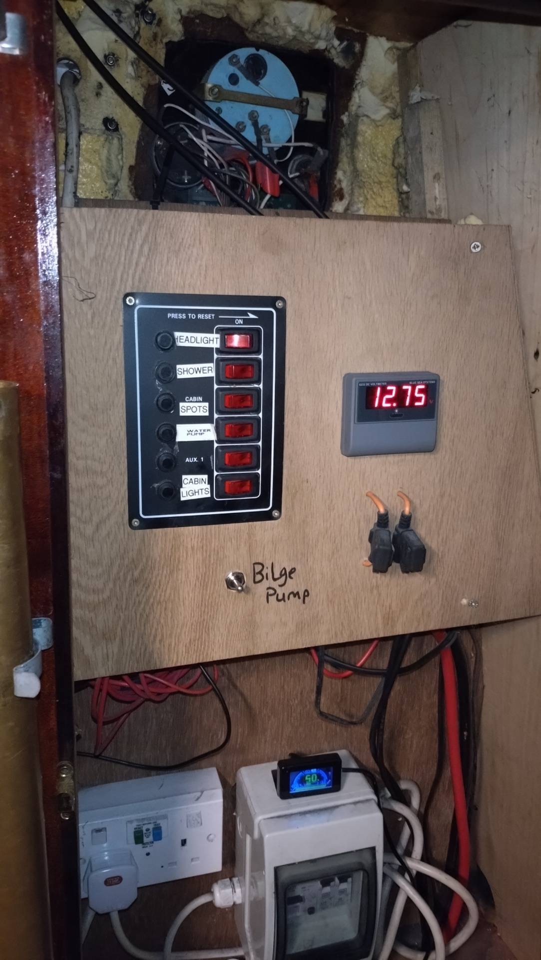
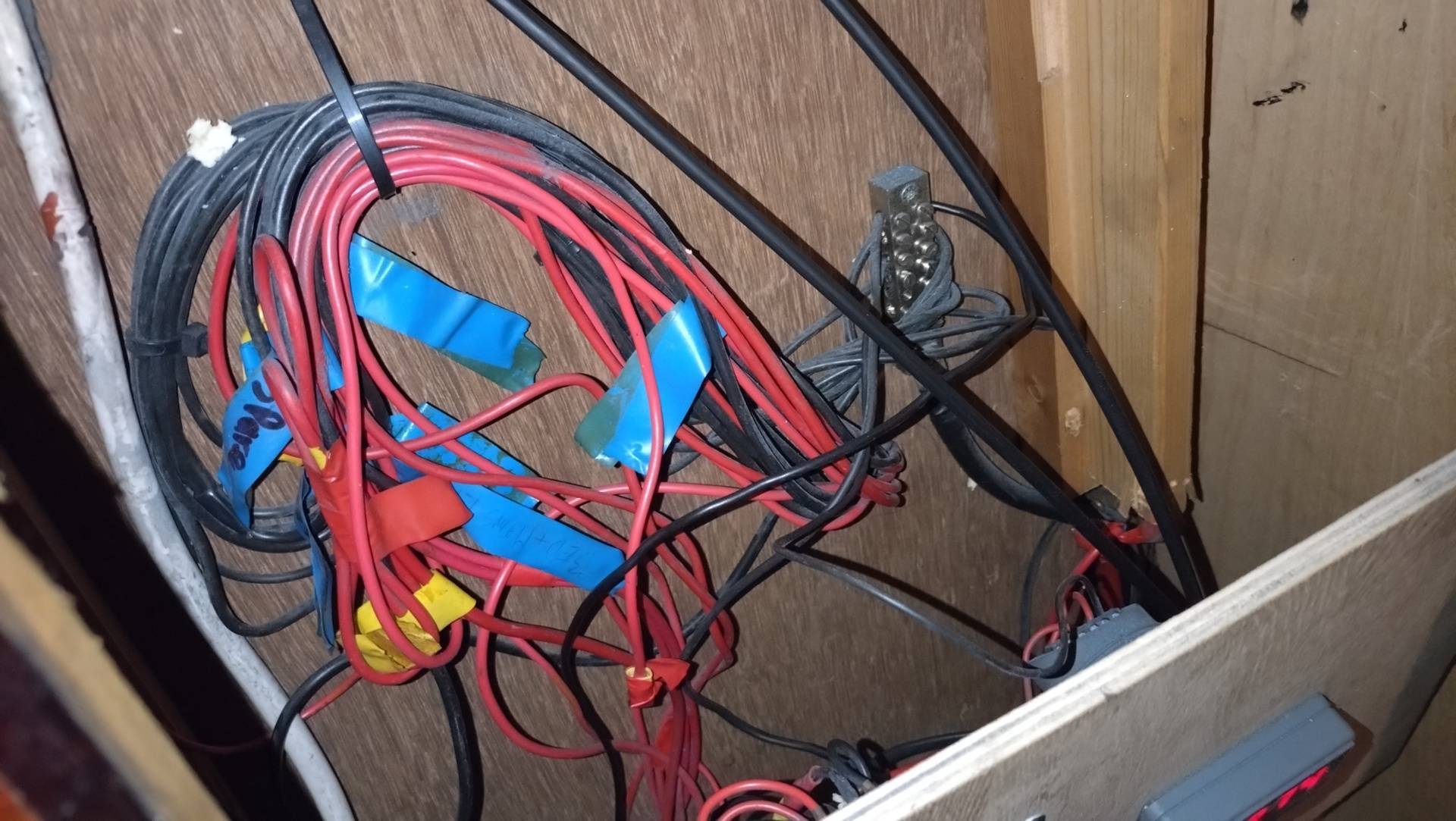
Hello all, I'm in the process of upgrading the electrical system in my boat and I wondered what you guys are mounting your inverters/charge controllers to? The old inverter I have is mounted directly to wood, which I don't really have an issue with as it doesn't get very hot, but I've added a Victron DC-DC charger which gets INSANELY hot, and I'm in the process of mounting a 50amp MTTP which I suspect will have a similar issue. Currently I have the DC-DC charger on a jerry rigged bracket with a fan behind it. Ideally I'd like to make an aluminium section raised from the wall with ventilation holes drilled in it, but I wonder if using a conductive material is a good idea? Also if anyone has any ideas on how I can clean up the mess behind my switch panel I'm all ears 😂. I particularly enjoy the 22mm cable spliced onto a piece of 2.5mm cable for the main feed! (Photos attached for your amusement, and apologies if the person who originally did this is on here.) All the best, MixingWizard

-
Reverse Engineering my Electrical System
MixingWizzard replied to MixingWizzard's topic in Boat Building & Maintenance
I'm aware of the engine restrictions, which is why I was saying that solar will be needed! I was aware they have a different charging profile but I didn't know about disconnection from the alternator - I'll look into it. -
Reverse Engineering my Electrical System
MixingWizzard replied to MixingWizzard's topic in Boat Building & Maintenance
Many thanks for your excellent reply. To follow up: The engine is a beta38. I have just fired it up to test the alternator. Of course my rev counter has decided to stop working (sods law) but at what sounds like roughly 1200 it is in fact putting out 50 amps at 14v - much better! Irritatingly one of the few pieces of information I got from the previous owner was to never run the engine higher than idle without it being under load - I'm assuming this is also incorrect. I've only just got back from work and it's too late to do a full charge, but if I ever get home before 8 I'll have a go at bringing the batteries back to life. I think I need to bump solar up by considerable list of boat maintenance tasks. Running the engine to charge is not really feasible for me as I'm rarely home from work before 7/8pm. I just had a look at the prebuilt lithium offerings, they have come down considerably since I built mine so that seems like the better option. -
Reverse Engineering my Electrical System
MixingWizzard replied to MixingWizzard's topic in Boat Building & Maintenance
I did have a look through this but it's not wholely relevant as I don't technically have a charger, just an alternator. Although cont to think of it that answers my question re the lithium batteries - it doesn't matter if my inverter doesn't support lithium (I can't see any dip switches on it unless they're under the cover) as I'm not using it to charge at all, I would still need some kind of DC-DC charger to interface between the alternator and the lithium cells but that's certainly cheaper than a new inverter. -
Reverse Engineering my Electrical System
MixingWizzard posted a topic in Boat Building & Maintenance
Hello, I could use some advice on reverse engineering my new-to-me narrowboat. The 230 system is fairly well installed but the 12v stuff looks pretty DIY and has given me a few headscratchers (tracing the wiring is a headache). For a bit of background, I'm not an electrician but I do a lot of site power work so I have a fairly decent electrical background, but mostly in 400/230v stuff. First off this is what I know: I've got an older Victron Phoenix compact multiplus 12v 1600 hooked up to 3x 110ah leisure batteries (Yuasa brand). I have two alternators, and from tracing the wiring it looks like the leisure batteries are charged directly from a fairly large alternator (which puts out 20a at 13v on idle - I'm not sure if this is good or not, it seems low to me but I was assured that it was fairly new). I also have a second smaller alternator attached to the starter battery. The previous owner of the boat wasn't particularly tech savvy but told me to watch the voltage meter (a Deep Sea single channel unit) to make sure I didn't discharge the batteries too much, which I have been doing for the last couple of months. I've recently been having issues with inverter cutting out after a few hours of use (initially I was getting a few days before the voltage dropped 1v down from the starting point, at which point I would charge them up). However, it turns out that the meter actually connected to the STARTER battery. What threw me was the second lead connecting to the leisure batteries, but it appears that that just powers the meter. I can only assume that this was a mistake during installation as that doesn't seem very useful to me - there's no way of monitoring the leisure battery voltage. Anyway, I suspect I've cooked my batteries by running them ridiculously low. They're currently reading 11v after 4 hours of charging and my 12v lights are dimming every time the water pump kicks in. So my questions are as follows: Is it normal to put a V meter on the starter battery and not the leisure batteries? I'm not on shore power, but if I were to take the batteries to work one at a time and put them on a recovery charge for a few days, are they likely to come back to life? If so, will they balance themselves when I connect them again? If not... Can I somehow connect to this older Victron Phoenix to change the charge profile to Lifepo4? I couldn't find the manual for it. I've built a few LifePo4 batteries for work and have a good source for cheap cells - I'd rather do that than buy more lead acids, but I also don't really want to drop £1k on a new inverter/charger on top of a new set of cells right now. I'll also be putting a few solar panels up at some point. Thanks for your advice as always! -
My mistake, I was talking about the sides, the base is 10mm and also with very little sign of corrosion. The builder is unknown but it definitely exhibits some annoying design flaws, such as a leaky side hatch (now resolved) and poor drainage above the engine bay. Then again the surveyor can't cover every inch of it so you never know what's going on under the concrete - for all I know it could have a crack in it which has rusted a nice line all the way around the hull!
-
The MDF is completely flush to the concrete so I'm almost certain this is the case. There also isn't at hint of hollowness when banging on the floor. At least this means I'm unlikely to have effluent under the flooring, although I'm not sure what it means for future maintenance. Thankfully the hull is pretty sound. It was built in 2000, and at its worst it was 0.4mm down from 6mm. Even that was a galvanic issue rather that internal degradation so I'm not overly worried. Now for the joyous task of tearing out the bathroom and removing the offending tank! Thank you for all your advice.
-
Just an update. My attempts at creating an access hatch have failed. I can't get any of the tiles up. With a bit of an excavation with a drill it appears my floor is tile on MDF, with what appears to be a concrete subfloor - is it possible the bottom of the boat has just been filled with concrete?! That seems like a terrible idea. It might explain the list though - if it's just a flat concrete base it won't have been balanced properly.
-
Thankfully this one is not built into the hull, and I'm fairly confident I could even get it out with one cut due to it's shape. I'm less worried about the tank as I was planning on replacing it with a composting toilet eventually - I'm more worried about what's happened underneath. I've got a good 5° list on the boat, which from experimentation takes about 500kg to correct. I was hoping this was just a fit out issue, or at the very worst water from the leaking mushroom vents that could be pumped out. I'm trying to think of a way of dealing with compost under the floor that doesn't end up with me effectively fitting it out from scratch, but perhaps I'm getting ahead of myself.
-
Just an update on this for anyone having a similar issue in the future - it turns out that the pre-2001 PRM120 does in fact have straight cut gears and is not supported by the update kit they released. We got it working for now by roughing up the surface of the clutch cone but it will be a new gearbox in the future. It's a shame but I guess 20 years is a long time in gearbox world!