Pete Morrison
-
Posts
47 -
Joined
-
Last visited
Content Type
Profiles
Forums
Events
Gallery
Blogs
Store
Everything posted by Pete Morrison
-
As in miles per hour / knots - given the leisurely pace of modern narrowboating, it seems a stretch that any boats could deserve the title "flyboat". I realise canals weren't the long linear moorings that they mostly are today with shouty fistwavy folks if you go any more than tickover (which of course I wouldn't). But wouldn't they have the same issues as we do today with generating a wake on most canals if you were to approach the 5mph speed limit, ending up limiting the speed anyway? Or is there some sort of shape that the hulls had to avoid that?
-
They should be? Or does the presence of acid make it uneconomic to scrap the lead? I have a few to dispose of want, nay deserve, a few quid for them. On the T&M near stone if that is relevant.
-
No I couldn't face doing prep right back to bare metal, at least not without being in a yard and craning the actual engine out. Danboline appeals because they claim minimal prep is needed (I'm not sure how much better it would have adhered with better prep). If I was building a new boat then sure epoxy would be great, but for this old thing I just want to give it a little love and call it good. Though it has been 5 years Id say probably 3 is what it was before it started to fail. I've done some of it but I think there is more now, so yeah you're right, let me start with that...
-
Indeed, the bund under my engine still has the original blue paint in top condition whenever I see fit to clean the gunk and water out from under it! As such I'm sure angle grinding the bund walls off would be very effective though possibly I would draw a bit of criticism every time the bilge pump went off..
-
I have a cruiser stern narrowboat and whether from rain or from drips from the stern gland (even just while cruising) it's basically impossible to keep it dry all the time. Five years back I painted the whole thing with Danboline, and it looked really smart for a while. I didn't do much prep as I was told Danboline sticks like the proverbial, but I washed out the engine bay and wire brushed and vactaned the rusty bits. Then two coats of Danboline. Over the years water made its way between the paint and metal and lifted the paint in places, and now I'm left with some rust coming through holes in the paint. Some bits when I press on them water comes up. I recall that it's not designed to have water standing. But all in all it does tend to make me think that it's not really worth doing and you're probably just as well off letting the rust itself protect the bilge. In the cabin bilge under the floor I used blacking and that worked a treat but it would make everything filthy to use in the engine hole. So now I wonder, do I just leave it be and let the paint slowly work its way off, or do I clean it up and give it a couple more Danbolines? I kind of want to just out of vanity but I'm not sure that it has much practical purpose...
-
I'm fairly confident that the wires for the loom are the Beta stock ones as they match up (in colour etc) with the diagram. So these should be 2.5mm^2 and 3m long. But plugging those values into a wire sizing calculator (12V, 40A, 3m one way trip) suggests a volt drop of 3V which seems excessive. Currently the power wire of the engine loom is not connected to anything at all (other than one end of the blown fuse) - it was cut off before entering the cabin. So I would need to rewire it in any case from the loom to the ignition switch in terminal. Which I could do, but honestly I think that the original system tapping the power off of the starter motor, and extremely awkward and probably a bit unfit for purpose fuse, going through the thin wire next to the loom, is inferior to the current system of tapping off the domestic with a nice, solid, accessible megafuse holder (which I could downgrade from 100A to 40A if that is advisable).
-
Exactly, yes. From battery positive, three parallel wires (I estimate 6mm^2 each), to a 100A fuse, then to all positives - ignition in and domestic. From the various positions on the ignition, wires lead to the places listed, mostly in accordance with the Beta wiring diagram posted above. (e.g. red wire from "heat" position to loom (position 11 on diagram) then to glow plugs.
-
I didn't suggest that, I said three thick wires come from the battery positive to the ignition switch (then on to the glow plugs, start and stop solenoids, and warning lights): Yes these battery positive wires form the other feed to the switch (as well as the rest of the positive terminal for the boat electrics). As I said, there's a 100A fuse on the positive terminal (which powers ignition as well as all other boat electrics). That's what I'm calling the distribution bus. Yes I think you are spot on and this is exactly what happened. It's clear to me that whoever wired the boat set it up in an unusual way. I could quite easily replace the fuse and shift the ignition circuit to the battery positive wire from the engine loom, but it would work out the same as there is only a single battery and the positives are connected in any case.
-
It's an inline fuse holder near the starter motor that looks something like this, it's very awkward to get at so I havent been able to open it to see what the rating is. I have traced all of the wires, that's how I found that this lead to the fuse. As I said there are three thick wires that come from the battery positive to the ignition so that's how the ignition is powered (glow plugs, stop solenoid, start solenoid, and warning lamps). I take it there aren't any other connections on the engine side or it wouldn't work (at least I couldn't trace any other connections on the engine side).
-
I have just discovered that the fuse on the Battery Positive connection of the engine wiring loom has been burned out, probably for as long as I have owned the boat. (Loom position 1, white/brown 2.5mm^2 wire). But there are three thick wires from my battery positive (red, yellow and brown) which go to my distribution bus (including ignition etc). What is this engine loom battery positive connection for? Should I replace the fuse? Or connect the other end to the distribution bus (which has a 100A fuse on it)?
-
Great, thanks for that explanation, very helpful. In fact the signal that the batteries are full could be quite useful? Although, the buzzer would probably be annoying if I wanted to charge the battery fully. If the alternators aren't regulated to the same voltage though I could imagine that the lower voltage one would not provide maximum output. I have LA batteries but I am considering Li (that's a whole other thread, though!!)
-
I'm really trying to understand. I'm sorry that I'm not as smart as everyone else. Are you saying that the way I'm describing the wiring is wrong, or the wiring itself is wrong? I interpreted what you were saying to mean that you should list wiring in order of positive to negative. So I edited my post to put it in order of positive terminals to negative terminals, but you quoted the old text.
-
I do have two warning lamps (and four buzzers now, but I haven't fitted them yet). Plan is to connect like this (positive side to negative side) ignition "on" position -> First warning lamp & buzzer positive First warning lamp & buzzer (in parallel) negative -> 40A Alternator Lamp terminal ignition "on" position -> 40A Alternator Ignition terminal ignition "on" position -> Second warning lamp & buzzer positive Second warning lamp & buzzer (parallel) negative -> 75A Alternator D+ terminal (the 75A alternator doesn't have an "ignition" terminal, so I believe this means the warning light is handled by the D+ only) Positive outputs (B+) of both alternators connected to my (only) battery positive.
-
I only actually have one dual-purpose battery for both domestic and starter, so the alternators are currently in parallel.
-
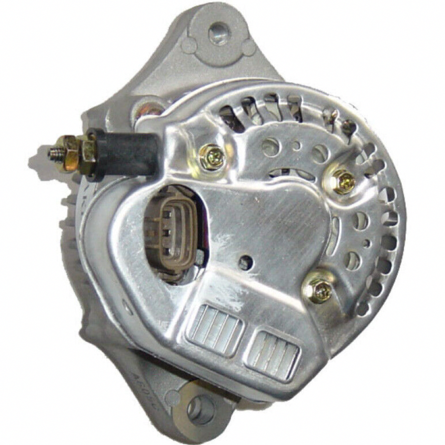
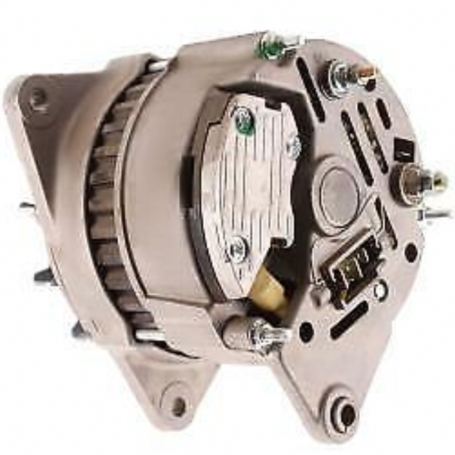
I'm not sure i understand what you're saying about the alternator terminal. I only have a D+ on the domestic alternator, and I thought that this should only be for the buzzer/warning lamp for that alternator? To explain. I have two alternators. I have a starter alternator like this where the three terminals (top to bottom) are marked Lamp, Ignition, Phase. The domestic alternator is a Lucas A127 like this, where the pins are (left to right) B+, B+ and D+. My understanding is that these should be wired like this: Alternator 1 Lamp terminal -> warning lamp -> ignition switch "on" position Alternator 1 Ignition terminal -> ignition switch "on" position Alternator 2 D+ terminal -> warning lamp -> ignition switch "on" position

-
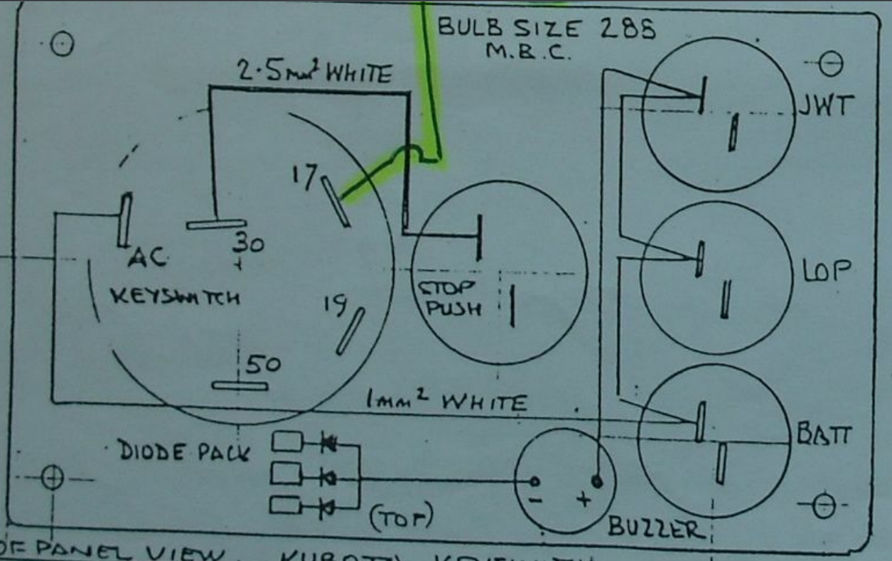
I have zero buzzers at the moment but I've ordered a multipack and will use one per circuit so as to avoid diodes and make debugging easier. Yeah I get that more wires are needed! But being missing from the diagram I didn't know where they go. I take it from the discussion that the other ends of the diodes (where "Diode Pack" is written in the image) get connected to each of the other (right side, in the image) sides of the lamps (thereby putting the diode and the buzzer in parallel with each of the lamps) - the same place the sensing wires get connected to.
-
Thanks for the correction, I'd never heard of a "sender" before until used in this thread so good to know the proper term to be accurate. I do have perhaps a silly question, but I can't really understand how to wire these new buzzers. With the one side of each of the warning lamps being connected to AC (battery positive, when the ignition is on) and the other side connected to the relevant sensing wire, where are the buzzers supposed to go, actually? My guess would be in series between AC and the warning lamp, so that when the relevant sensor "activates", it acts as a negative (e.g., low oil pressure causes the switch between sensing wire and engine block to close, high temperature causes that switch to close) both the buzzer and lamp would turn on. But that doesn't seem to be how this diagram describes it. In fact, it doesn't seem to describe where the other end of the diode pack is connected to?
-
Thanks for the advice. I think adding buzzers for each circuit is a much better idea than diodes as this will make it a lot easier to debug if they ever do go off. I also think I'm just going to replace the oil pressure sender, they're pretty inexpensive. This one for 14 quid says it will fit a Kubota v1505 (beta 38). https://www.ebay.co.uk/itm/365357245925 Can anyone give me the answer to this? I thought it was supposed to turn on when the ignition is on but engine not running, so that you can know if the bulb has failed? If it's not going to turn on ever unless overheated, then I will take the sensor out and test it. Feels unlikely for both the oil pressure and water temperature senders to fail simultaneously, unless it was a voltage spike or something that destroyed both.
-
Or - just not have buzzers and rely only on the warning lights? Ok - so normally when you turn the ignition to the "on" (AC / accessory) position, the alternator and oil pressure lamps should light, but the temperature light doesn't turn on anyway? I think it would be worth in that case taking it out and putting it in boiling water to test it.
-
I tried both. I also tried connecting the end of the diode pack to both battery +ve and battery negative. And both polarities for all combinations. So end connected to batt +ve: tail1 to end, tail2 to end, tail3 to end; end to tail1, end to tail2, end to tail3. End connected to batt -ve: tail1 to end, tail2 to end, tail3 to end. end to tail1, end to tail2, end to tail3. End hanging loose: tail1 to end, tail2 to end, tail3 to end. end to tail1, end to tail2, end to tail3. None of these combinations showed any continuity at all. I removed the whole diode pack and tried tail1 to tail2, tail1 to tail3, tail2 to tail1, tail2 to tail3, tail3 to tail1, and tail3 to tail2. I would definitely expect one or the other polarity to work if the diodes were all functioning? None of these showed any continuity. With batt +ve -> lamp -> oil sender wire -> oil sender terminal, lamp does not light. If I then connect the oil sender terminal to engine block, the lamp comes on. So that suggests the oil pressure sensor may be faulty? Same happens with the temperature sender - connected up batt +ve -> lamp -> temp sender wire -> temp sender terminal, lamp does not light. If I then connect the temp sender terminal to engine block, the lamp does come on. -- From all of this, it would seem that both of the sensors AND diode pack are all fried. So I should try replacing them all? Any idea what diodes the pack uses? Should I get a buzzer as well and if so what would the spec be?
-
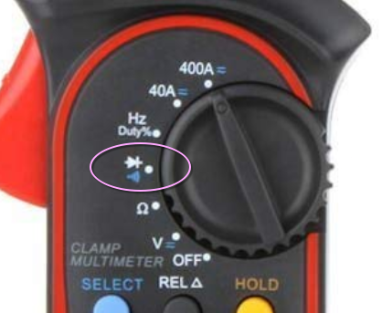
I used a UNI-T UT203 multimeter on this setting (I always just thought it was the "continuity" setting). I tried both polarities as it has that little diode symbol suggesting it will only work in one direction. Did this, still no lights. But I think there is likely to be more than one problem. I tried connecting directly: +12V -> bulb -> oil sensor wire -> (i assume earthed through engine). No light. So to me, that suggests faulty oil sensor as well, maybe? I also tried connecting directly: +12V -> bulb -> engine temp wire -> (i assume earthed through engine). No light. So maybe also faulty temp sensor?
-
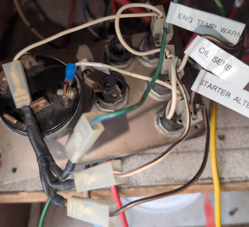
The alternator/oilpressure/temperature lights haven't ever worked on my control panel which is of this type. All of the lightbulbs work when directly connected to 12V. The AC (accessory) position of my ignition switch isn't working (new one on its way) but if I wire it up directly to simulate "on", it doesn't light the lamps either as I think it should. I don't have a buzzer but otherwise I think the design is the same. I have tested continuity between each of the wires and labeled them (eng temp goes to a wire attached to the outlet to the calorifier, oil goes to a wire attached under the dipstick, and alternator goes to the starter alternator) I thought that black heatshrinkwrapped 1-to-3 connector was just a connector, but maybe it's the diode pack. And maybe the one end is supposed to go to battery negative? I tested continuity between every pair of inputs and outputs into that 4 way thing, both polarities each time, and nothing whatever. Do I need to replace this? Here's a photo of the back of my panel. Diode pack(?) in bottom left. Onlu the warning lights and the connection to AC are connected at the moment.
-
Beta 38 (BV1505) stop solenoid replacement
Pete Morrison replied to Pete Morrison's topic in Boat Building & Maintenance
Thanks for the advice, correct solenoid on its way. The plunger seems to be well lubricated and pushes back very easily, applying finger pressure on it while energising the original solenoid makes it click clack back and forth very satisfyingly. That's why I wondered if anyone knew how they sprung back, and perhaps how to open the thing up to attempt a repair. I guess it may be a coil spring inside that has perhaps broken. But that does not align with the apparent cause of the failure, which was the stop engine button sticking down and leaving the solenoid energised for several days on end. -
Beta 38 (BV1505) stop solenoid replacement
Pete Morrison replied to Pete Morrison's topic in Boat Building & Maintenance
Like for like replacement could be simpler. I'd need at least a 3m long cable to position the stop handle conveniently, it would also involve cutting holes in the boat and having a new obstruction in the engine bay. That's not to reject the idea outright - as you say no electrics is appealing after a failure of the solenoid (several decades old but still). But I would like to first consider repair or replacement of the solenoid. Any idea how the solenoid is supposed to work - is there an internal spring that I could get at somehow? And any idea why the replacement isn't working before I return to sender? The new one still only has two terminals - perhaps the "third wire" is meant to ground through the engine block - should there be 12V applied to both terminals to make it "run"? -
Beta 38 (BV1505) stop solenoid replacement
Pete Morrison replied to Pete Morrison's topic in Boat Building & Maintenance
Would love to, but I don't think that will be easier or cheaper than replacing the solenoid (assuming I could find the right one)