aaronwood66
-
Posts
30 -
Joined
-
Last visited
Content Type
Profiles
Forums
Events
Gallery
Blogs
Store
Everything posted by aaronwood66
-

How much does the alternator pulley size matter?
aaronwood66 replied to aaronwood66's topic in Boat Building & Maintenance
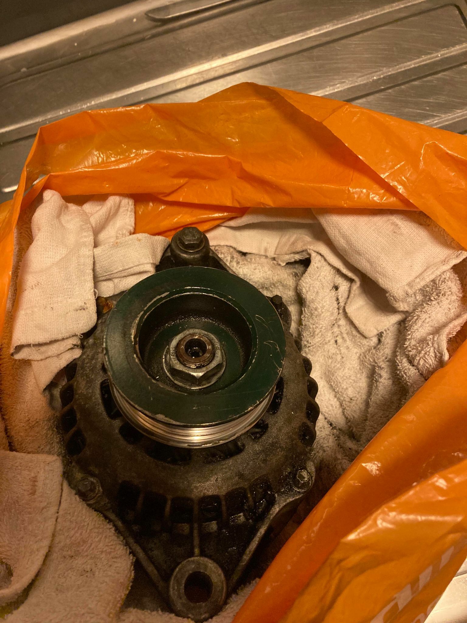
Just to update this thread... I was hoping to keep the 'new' pulley as, like someone said, it would likely be better charging. However, the old pully had a built in spacer that means the new would would not line up the same with the belt, so I had to swap over. I found a great little place called The Starter Bay in Gloucester that did this for me in the matter of minutes. So all is well now Thanks for everyone's input! -
How much does the alternator pulley size matter?
aaronwood66 replied to aaronwood66's topic in Boat Building & Maintenance
Well spotted from the paint - it is a Beta Marine engine! Thank you, all, for your advice - I shall keep the 'new' pulley on the new alternator. It is the starter alternator on my engine that feeds the rev counter / tacho, so all good there -
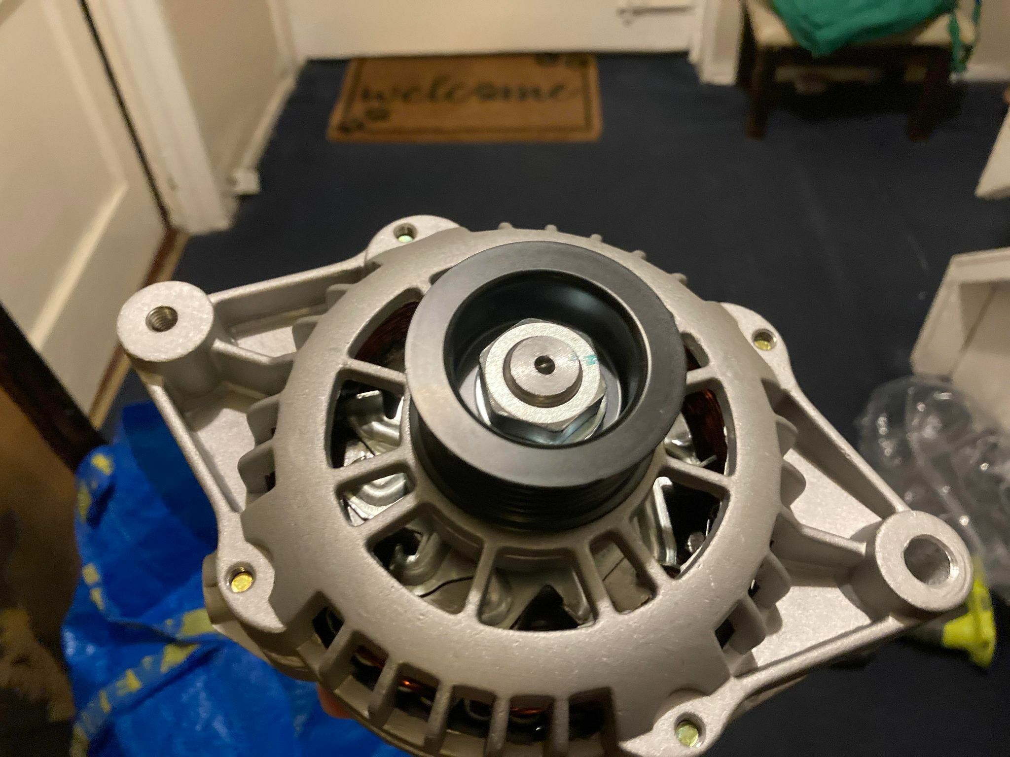
I am replacing my 100A domestic alternator - the model is pretty much a straight swap. Easy enough there. However, the pulley that comes with the new alternator has a 55mm diameter, where as the old one was 80mm. As it seems to be VERY difficult to swap them over (I have tried myself, although keep reading that an impact wrench is the only way) - I was wondering if I can just keep the smaller 55mm pulley? Will that affect anything?

-
That definitely sounds right, from the best I could do to follow that wire to where it came from and went.
-
I'm definitely going to replace the isolator switch with a better one - are there any recommendations? (This one perhaps? https://www.12voltplanet.co.uk/marine-battery-isolator-switch-2-positions.html) Also, good suggestion - I have the electrical spiral wrap on order now I never actually considered the vibrations are what could have (most likely) destroyed that blue/black wire. (I'll do a bit of digging later to find exactly what it's for) Yes, the engine started this last time, but not since the burning smell (when the isolator swich melted so no connection) Agreed - this was how the boat came to me 3 years ago and although I made sure to get wires and stuff out the way of all moving parts, I never considered the vibrations being a factor, especially on angular edges like that one... a good point made
-
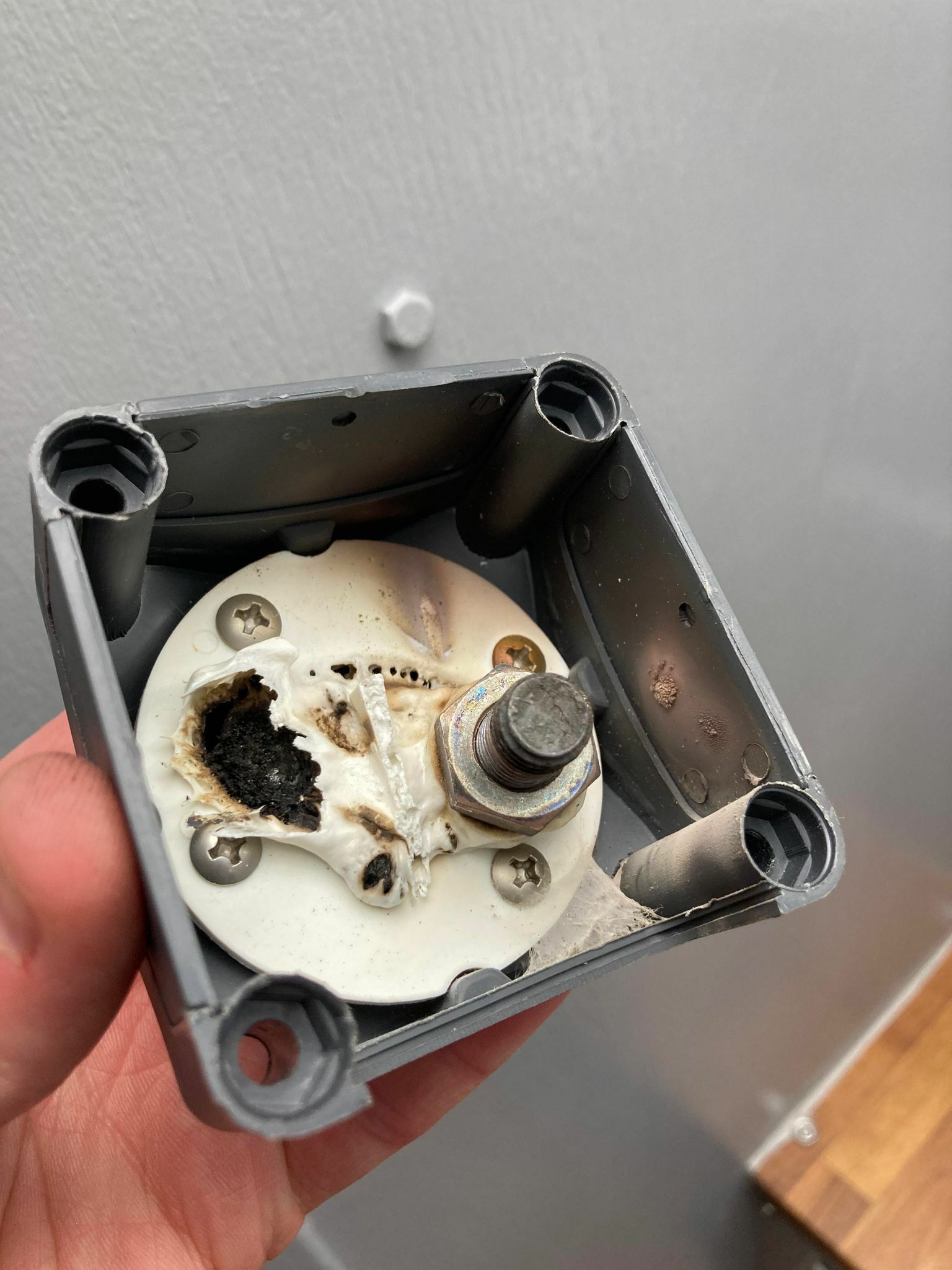
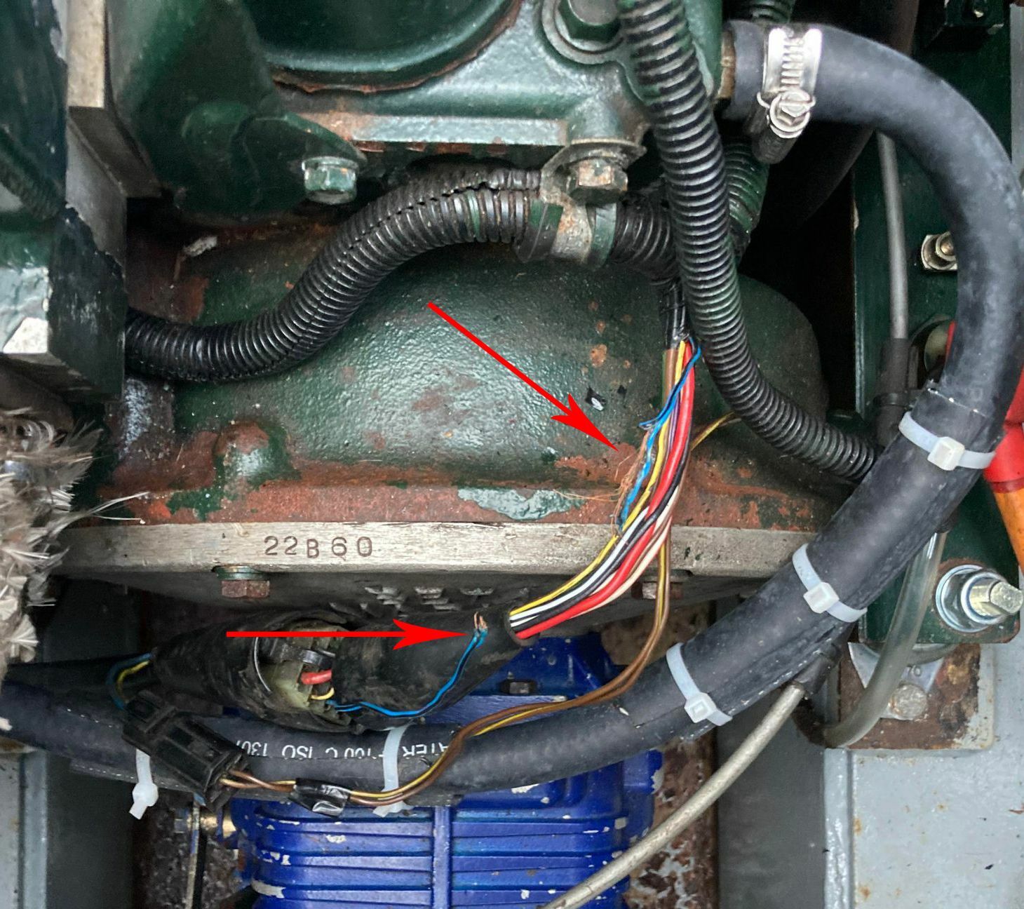
I have an electrical fault that I can't figure out how or why has happened, and I don't want to make the mistake again by just replacing everything only for something to go badly wrong without understanding why... Last week I was running the engine and noticed smoke and a burning smell coming from the engine bay. I immediately turned the engine off and waited for it to cool down before inspecting. I found 3 places where there was evidence that something seriously had happened: The starter battery isolator switch had completely burnt out/melted - I could no longer turn the switch (see photo) The electrical harness for my Beta Marine engine had one melted wire. (It is blue/black wire and it seems to run from the starter battery alternator to the Beta Marine control panel, as far as I can follow it.) (see photo) Where I had a piece of kitchen towel wrapped around my oil dispenser tap, this was touching the side of my starter motor. The paper towel was black and had singned (although not caught alight.) The burnt wire in the electric harness was strange that only one had melted, and in a place just above part of the engine. I don't know if it had touched that part of the engine and the hot engine melted it - but then why only one wire - there was no evidence of even slight melting on the others. I just don't know which thing caused this chain reaction - a melted harness wire? Did the starter motor overheat and cause this? Was it a dodge isolator switch? If anyone could help with any suggestions of what might have started this, I would be very grateful. (P.S. The isolator switch was new in Feb, and hasn't shown any problems in the months leading up to this - https://www.amazon.co.uk/dp/B07P8KCV35)
-
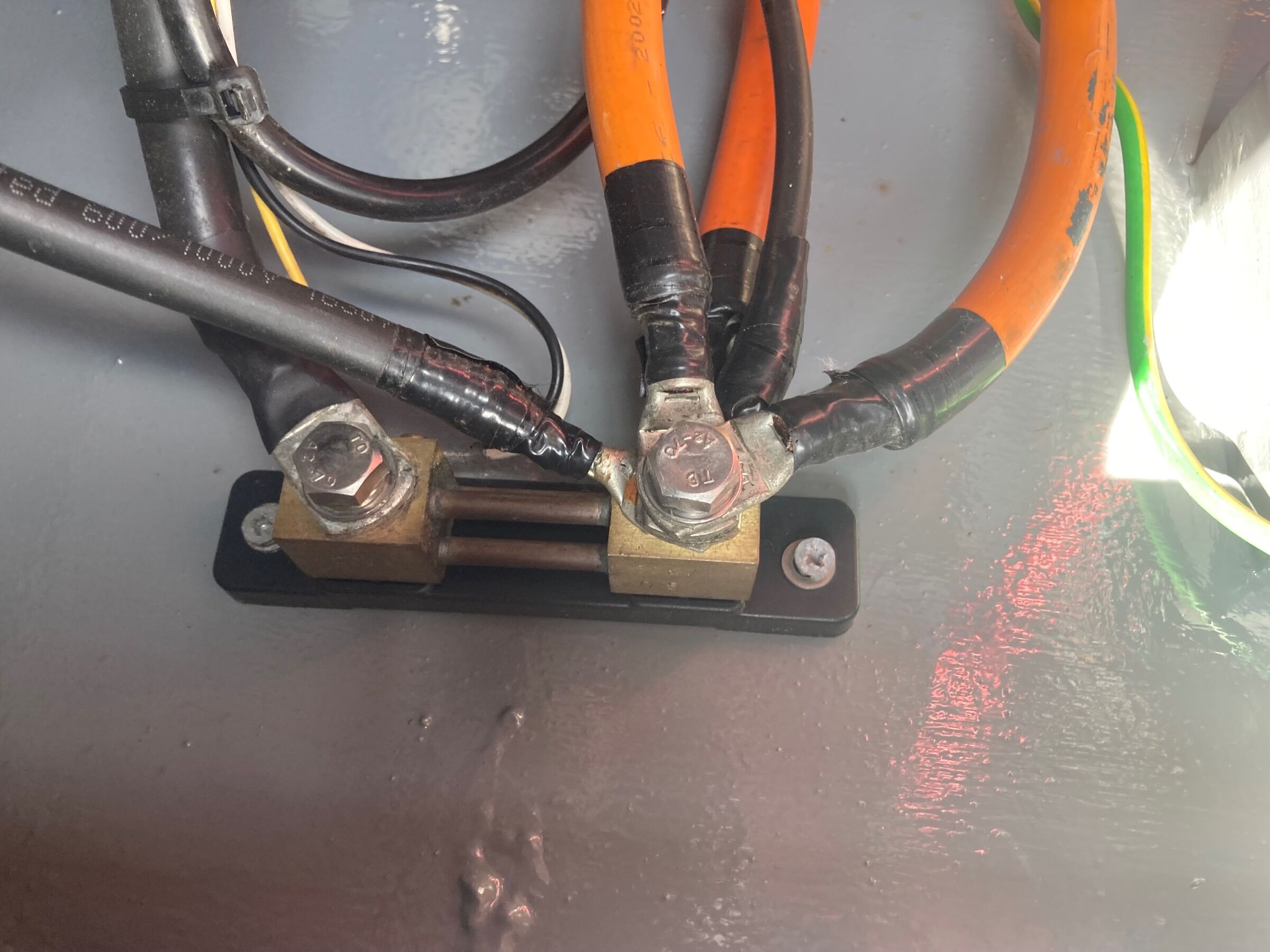
Finally the rain let up and I managed to have look. I undid all connections on the shunt and inspected it - I couldn’t see any obvious damage/problems. But on reconnecting everything (just before I was going to check your idea @MtB, the 199A issue went away and it appears normal again). Not sure if I wriggled something on the shunt and it might still be faulty… I’ll keep a close eye on it. Thanks to everyone for their input and help.
-
Thanks for all these comments - a problem with the shunt is certainly something I never considered, as it just looks so solid and sturdy as components go. I know it is wired correctly (as it has been working fine for the past few years) but when I go back to the boat this weekend I will take a photo and examine it more closely. And report back. Thanks!
-
Thanks very much, @Tony Brooks and @MtB I had tried to disconnect everything and left it half an hour before re-connecting, but it was still stuck on 199A. The shunt seems OK - it's mounted high up an under a ledge in the engine bay, so no chance of water getting in/around. Nothing has come loose. Very strange! MtB - thanks for the Victron recommendation.
-
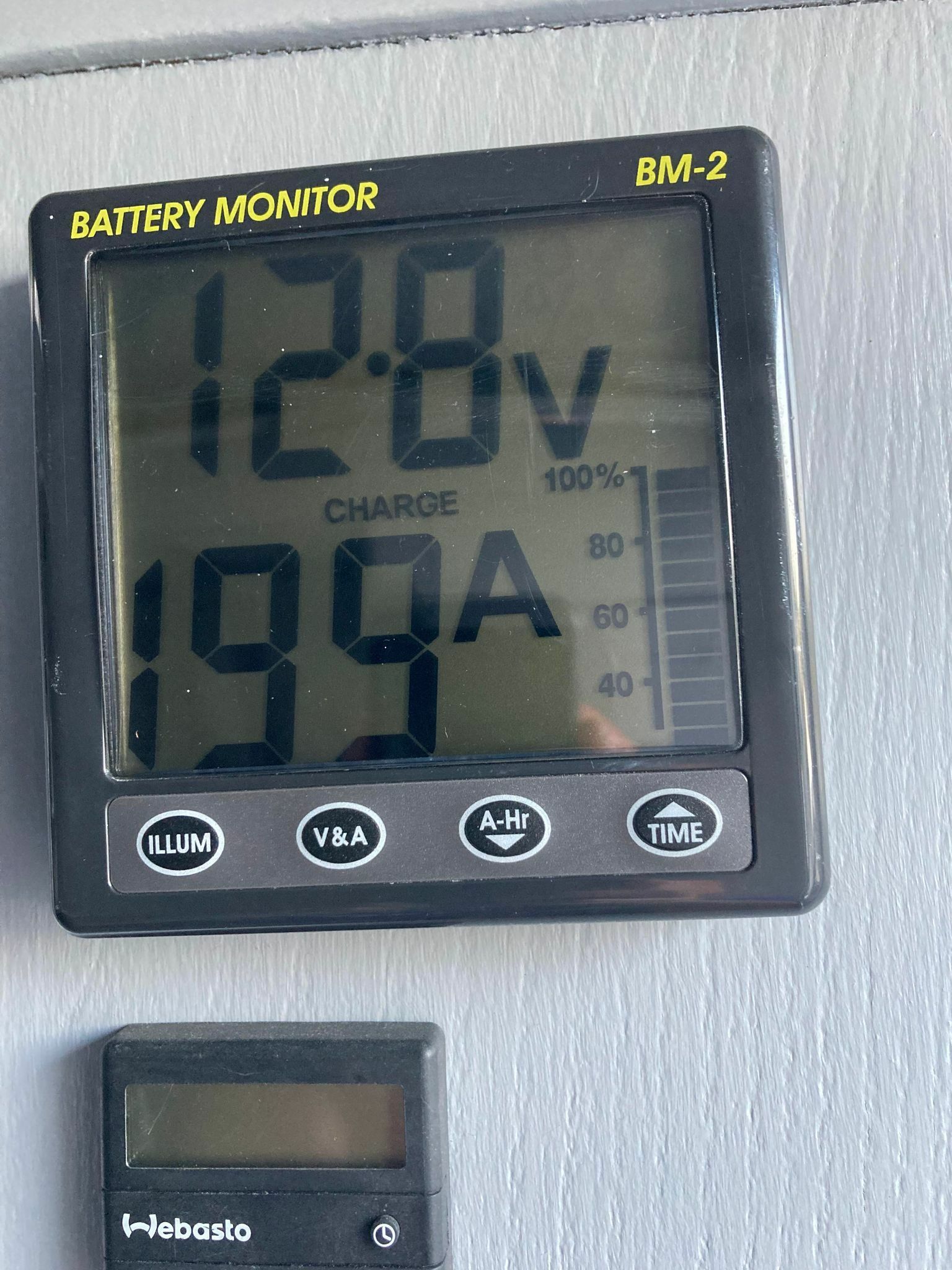
Having finished my renovations, I have been staying on board a lot more. I don't use a great deal of power - I have a fridge but don't use it, so the only power used is charging USB devices, lights, and the general essential boat appliances, (plus Webasto in colder months). Between running the engine and the last few sunny months, I have always had topped up batteries, so I had a bit of a shock when my Clipper BM2 battery monitor started to show some strange readings. It came with the boat, so I don't know how old it is, but I have been using it over the past few years without any issues. I woke up yesterday to find the Amps reading seems to be stuck on 199A charge. It still says this when disconnecting all charging methods, and turning all loads on at the same time. I have double checked the connections (everything fine), and also ran through the set up procedure from scratch, No luck. My batteries are reading 12.9 on my multi-meter, so nothing seems to be wrong there. I am stumped and thinking buying a replacement battery monitor might be the only way? Any suggestions before I do this would be much appreciated :)
-
From what I have seen this looks like a fiddly job, but I am the patient type And I have just bought a feeler gauge to get the correct fit
-
Thanks again @adrianh - I managed to take the nuts off you suggested and it worked like a dream - I can now lift my engine
-
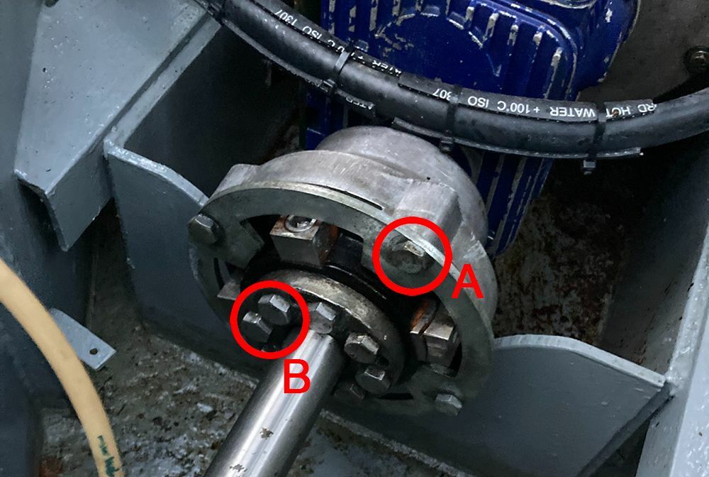
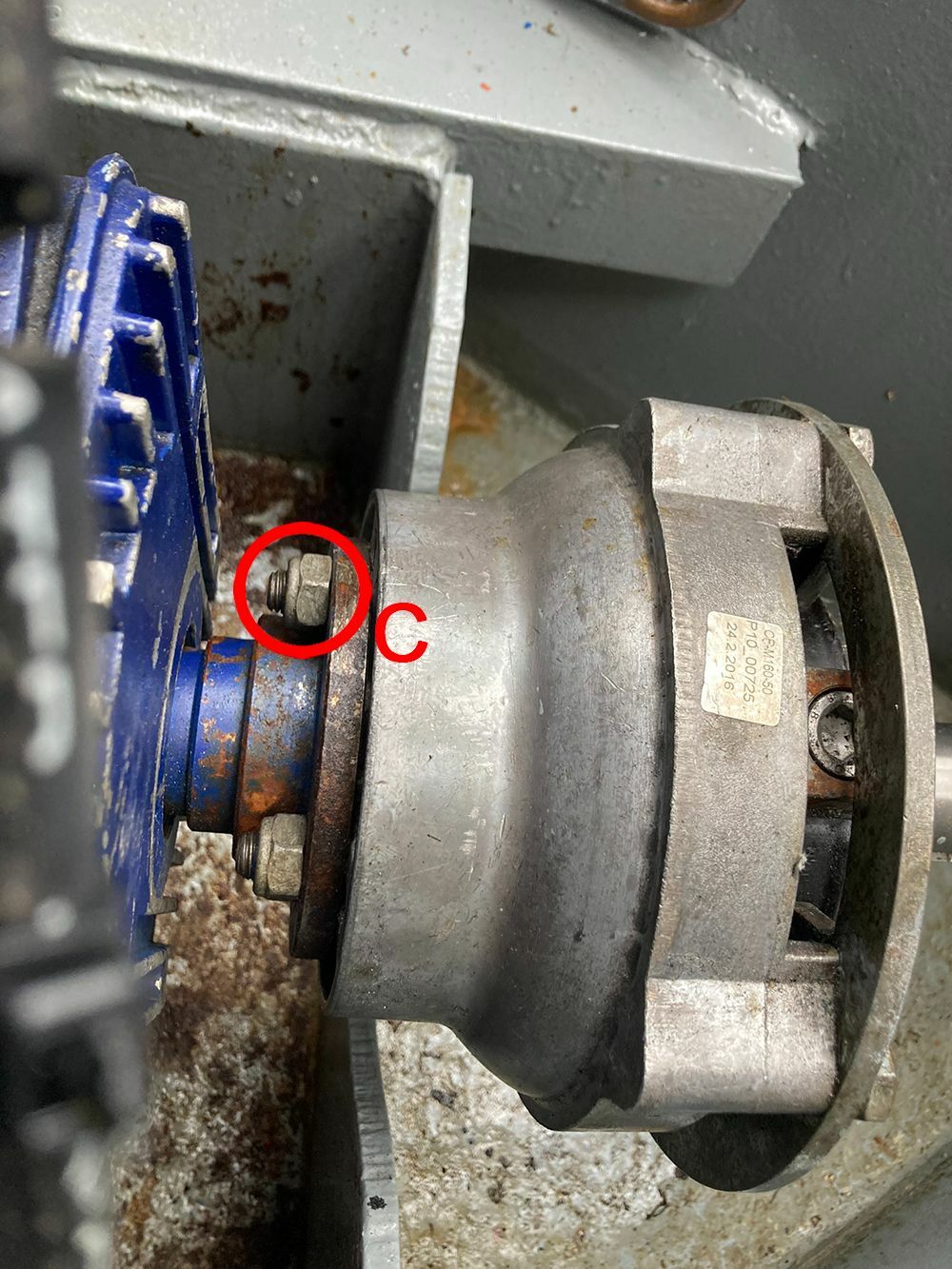
I am really grateful for your timely reply, as I was attempting to remove the 'B' nuts today and they were so tight that I didn't have any luck budging a single one today - no wonder, from what you've said! I think the C bolts may be my best bet, and there are only 4 of them. Thanks also with what bolts these are likely to be - I will let you know how I get on
-
Thanks @Tony Brooks - I worded it incorrectly, but yes, I meant I I wanted to disconnect it from the gearbox. Thanks @Tracy D'arth - I am going to go with the B bolts - many thanks for your help!
-
The time has come for me to replace the engine mounts on my Beta Marine 35 engine. Thanks to this wonderful forum, I (think I) know what my plan of action is and how to do this. I realise I will have to remove the prop shaft to raise the engine, but am having trouble understanding which of the many bolts will do this on my coupler - a Centraflex M160. I don't know if it's because my boat is 20 years old, but I can't find any manuals, videos or articles that explain how. Other videos show very different couplers than this, that tend to have 4 bolts only - but this does not correspond to what I see on mine. I have attached a couple of photos to show my setup, and if anyone can help me identify what the A,B, C bolts are, and which need to be undone to remove the prop shaft. Thank you in advance for any help
-
I did have one follow up question, now that I am going to go with a new marine exhaust skin fitting... I know the importance of creating a swan neck with the exhaust pipe, so wondered which way up I should install this skin fitting? I imagined with the angle pointing upwards, so as to create the upward angle for the swan neck - but a lot of videos/images show it pointing downwards
-
Thanks for the tip - I will do anything that makes this easier! @Alan de Enfield Sorry, I didn't mean the exhaust pipe fits through a 13mm hole, but that is the opening diameter of this skin fitting I have. This welded on skin fitting has rather thick walls, so the marine exhaust hose/pipe fits nicely snuggly over it. Anyway, I will be removing this completely now It is a refurbed marine one from ebay.
-
Thanks @Alan de Enfield - The unit itself is refurbed, but I have sourced the other kit parts from Webasto, Mellor, other online places, etc. I hadn't bought an exhaust skin fitting yet, as my query was whether I could use an existing welded on skin fitting that was previously used for the bilge pump's outlet. It seems that, no, it would not be wide enough, so I will go ahead and buy a marine skin fitting as you suggested, and take @Tony Brooks's advice on how to drill the new hole
-
Thanks Tony, this is a great suggestion on how to tackle this problem!
-
I have found the perfect place for my refurbed Webasto Thermo Top C in my engine bay - close to the fuel line, batteries, etc. For the exhaust outlet, I am thinking about using an existing skin fitting from the bilge pump. It is high up, in a perfect location, and a welded in one (steel). However, I wanted to ask if anyone knows if there was a minimum diameter an exhaust skin fitting needed to be for a Webasto boiler? (I mean the hole that the fumes escape through, not the entire skin fitting diameter.) This hole diameter of the existing one is 13/14mm. And my Webasto exhaust pipe fits nice and snuggly over it otherwise
-
Mystery thermostat - can't work out what it is for
aaronwood66 replied to aaronwood66's topic in Boat Building & Maintenance
Thanks so much, Tony - this is a great insight -
Mystery thermostat - can't work out what it is for
aaronwood66 replied to aaronwood66's topic in Boat Building & Maintenance
This is the mystery - there is a cupboard and wall I don't want to rip out where the cables go. There were not 2 red cables connected to the old Alde, but these could have been connected at one point to one of 2 pumps that I have long since removed. I will still try and get to the bottom of this, but for my Webasto install, I won't let it get in the way. -
Mystery thermostat - can't work out what it is for
aaronwood66 replied to aaronwood66's topic in Boat Building & Maintenance
Thanks to everyone who has replied to this, and for identifying it as a cylinder or pipe thermostat (more likely the latter). And from everyone's explanations, I now understand (at least in theory) what this kind of thing is used for - many thanks! From what everyone has said, it sounds like whatever reason this was installed for, it will not be necessary with my new Webasto install. Thanks for this suggestion - I will take a closer look to see if this has been done on mine -
Thanks in advance to anyone who can help with this. I am nearing the end of my narrowboat renovation and have got my head around everything thrown at me so far. However, I can't work out what this is/what it does/or where it is connected. I am in the process of replacing an old Alde gas boiler with a Webasto diesel boiler, and but the one thing I am not replacing is my calorifier. This thermostat device has been resting on the floor here, with these 2 wires running up inside the wall. I can't really remove the wall or surrounding area easily, so wondered where they were going to, and if it had anything to do with the old Alde, or is this for the calorifier? I have no idea what to do with this, or how it works? Sorry, I have been trying to search for an answer but just can't seem to type the words to get me an answer!
-
That's a good idea, but I would have to take apart 3 different rooms to be able to do that