


Kelbs
-
Posts
51 -
Joined
-
Last visited
Content Type
Profiles
Forums
Events
Gallery
Blogs
Store
Posts posted by Kelbs
-
-
Still overheats when plugged back together. Pointing towards a manufacturing problem. What a long process of elimination!
-
Ok, I've made a bit of progress. Finally. I connected the circulation pump directly to a battery and it pumped water around freely. I then turned the webasto unit on and ran that, with the pump still on the seperate feed, for about 5 minutes and have managed to get hot water into all of the rads. This to me is a huge step in solving the issue here.
Now, does anyone know what this may be?
-
33 minutes ago, Tony Brooks said:
I agree with that. However you now say 22mm where as a few days ago you were talking abut 28mm so its no wonder I am having problems.
I do wonder if by some chance the impeller has fallen off the motor spindle but the you say that upon shutdown it circulates cold water (not sure how you know that through). this is no more than a faint possibility.
The 28mm pipe is the black flexiable hose running from the webasto to the bulkhead, 28mm external, 19mm internal. After the bulkhead the 22mm pipe starts.
I'm assuming that the pump starts circulating the water because within two minutes of the shut down cycle the webasto unit and the black hose go from being too hot to touch to being room temperature again. I thought this was due to tje pump circulating..
It's all terribly confusing to be honest.
-
Hello Boaters,
I'm soon to fit the multi-fuel stove on my 57'x10' boat and have been trying to work out what flue system to install. The stove is the Ecosy+ Ottawa 5kw curve with stand. I realise there are going to be people advising both options but talking it through with you folk will help me come to a conclusion.
I would prefer to fit the single wall, standard, non insulated 5" flue for these reasons:
- I already have the flue needed and wouldn't have to buy a new insulated system,
- I don't like the size and chunk of having a 7" flue in my boat.
- I don't like the silicone flashing which seems to come with the kits
- I can't think of a way to have a removable chimney for those potential low bridges (I know there are some as low as 7ft) and the BSS states that there needs to be 2m of flue and at least 600mm external. If using the twin wall then this would be a massive pain in the arse to remove if needed for the low spots.
From the research I have done, it seems that the twin wall is only recommended and there are no solid rules in place enforcing the installation of these flues. I know it is the current recommendation but is it really that dangerous to have a bit of hot flue around 3" from the plywood wall, at its closest point?
I have read people on this forum saying that its only new boats which need to be fitted with the twin wall in order to comply with the RCD. My boat is new but I can't find any information other than this forum which states that the RCD requires this.
Cheers,
Beau
-
58 minutes ago, Tony Brooks said:
Or a major restriction in the pipework somewhere e.g. rad valves turned off or set too far closed,TVR (mentioned before), If one is fitted a heat & water or water only valve wrongly connected or set but without a detailed diagram we have no idea what the OP has so it is all guess work..
I have flow and return pipes, 22mm, which run down the length of the boat, the rads are all teed off these pipes with 15mm pipe. All the valves are open and the TRV is still fitted but I can't see why it would be a problem on this system as it is teed off the main feeds.
-
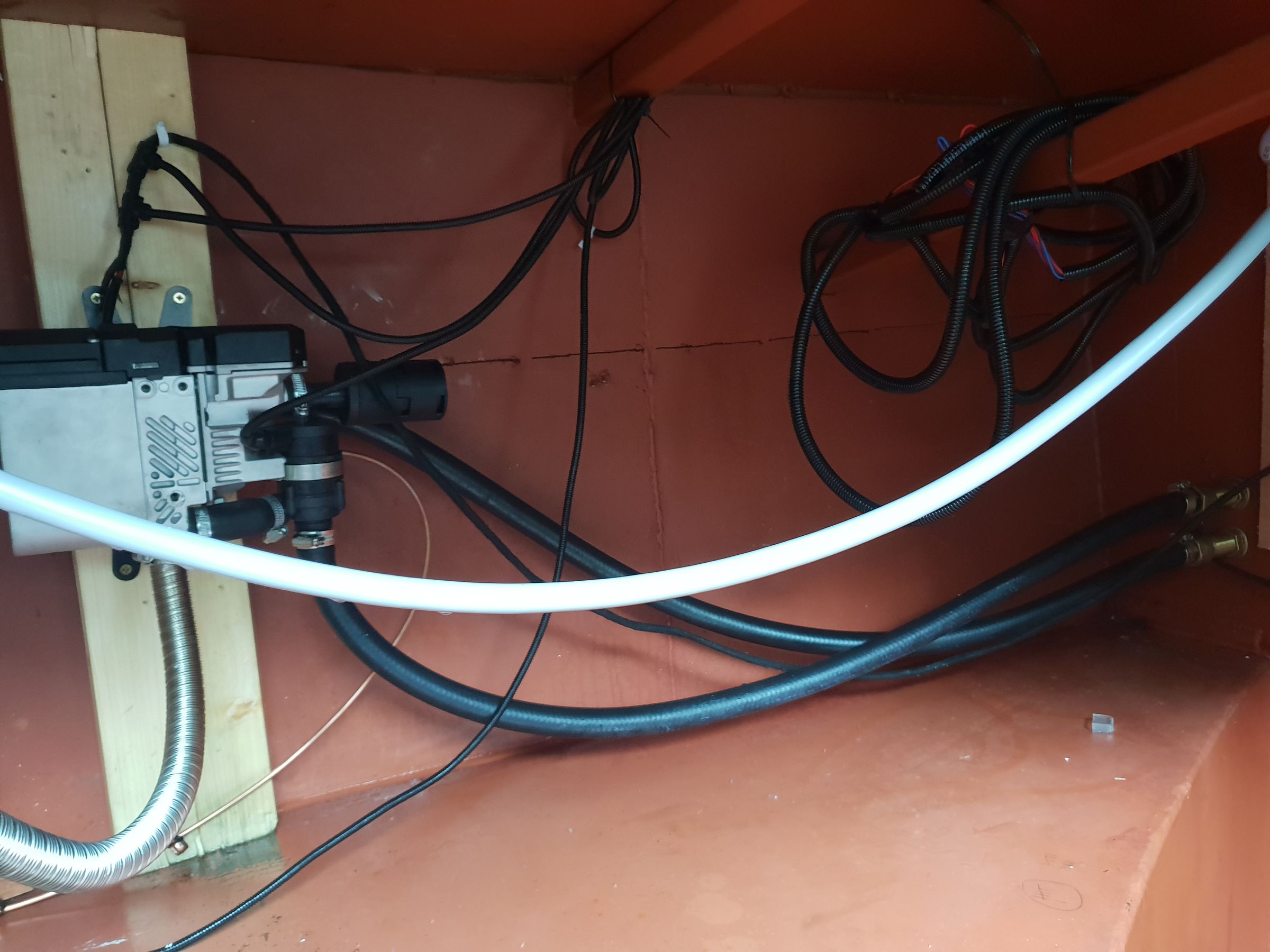
So the pump is attached to the unit, as in the picture. I don't think it's a Webasto pump, as the fuel pump isn't and the unit is a recon so I wouldn't be surprised if the parts were cheap replacements.
31 minutes ago, chevron said:Pumps fastened to unit connected by short rubber pipe,I have wondered are coolant pipes the right way round at unit is it drawing the coolant from the radiator circuit and not direct from the header tank ?

The return pipe is coming directly from the header tank into the Webasto unit, via two elbow bends. The pipes are most definitely the right way around, as in the flow is the flow and the return is the return.
-
I tried to upload a video of the webasto trying to start up but it was struggling. I'm still at the same point. I've bled plenty by of coolant from multiple points on the system. Once the heater has cut out due to over heating it starts it's shut down cycle (I've assumed) in which cold water is easily pumped around the system until the unit is back to being w normal cool temperature. I don't know how this could work if there was air trapped.
Sorry I didn't reply to the bucket trick but it didn't seem like the best test for me.
-
Not sure if this is of use to anyone but it's what I'm dealing with.
-
Ok, I've just lowered the pump by about 8 inches. When it says that the pump is not self sucking, does that mean its relying on the water feeding itself into the pump, then the pump can push it around, not pull it as well?
It still cut out, I will try draining the excess steam now (already scolded myself once today) then I will attempt a restart.
-
3 minutes ago, chevron said:
Said it was air at the start drop the webasto unit so it is near the floor it’s only three screws to do this as the exhaust and fuel pipe will bend this will make it so the water pipes supplying unit are not going uphill to unit getting rid of air traps
I've bled the air out of the system though, I don't think this is the issue.
Dropping the unit will lower its overall height but the supply pipe will always have a bend, creating a little possible air trap, no matter how low it goes. Regardless of this I have spent the last two hours bleeding litres and litres of coolant out of the pipes, which would have pushed any air out, but the unit is still boiling the water and the pump seems to turn off. I don't see why the pump would turn off while the unit is still heating water if there was air trapped.
-
Right, quick update. I went into the boat yard to buy various bits for the bleed points but was advised to try bleeding the webasto unit again. This advice was from a Webasto installer. I've just finished bleeding and there was a lot of air in there but I think this was mostly steam from the boiling of the water. Apparently the pump is plenty strong enough to push the air bubbles to the natural bleed points.
Still there is no real progress.
The pump seems to work fine for a minute or two, I can hear the water moving around the inside of the boat but then heater starts to heat up the pump appears to turn itself off. So I am now thinking that it may be a pump issue instead of an airlock.
I opened the pump up, as recommended by the seller, and turned the blades inside which moved freely, which would indicate that the pump is ok. Perhaps its an internal electrical problem? I have no idea.
I think I may just send the unit back, unless there are any Webasto installers who service the Bath area and fancy coming out over the weekend?
-
Thanks for that Tony. I couldn't get the plastic pushfit pipe to fit inside the felxiable pipe, even when heated and lubricated, does the copper pipe have a smaller outer diameter, if so then that may well work.
Just thought and they actually have to be the same size to fit into the same fittings.
-
10 minutes ago, Detling said:
Only on small bore pipe with a much more powerful pump. The engine pump can often blow the air out of a calorifier coil but it's on a B* great engine so the power is not low, the Webasto pump is low power because otherwise it would have to use loads of amps instead of the 3 it does.
Fit a T piece with the T pointing up and then put any decent valve on it or even an automatic bleed valve, but in my experience they drip forever.
Any advice on where I could find a T for the 28mm hose? And then what sort of valve could I put on that?
I'll try to call in to The Boat Yard after work tomorrow and see what they have.
-
47 minutes ago, Tony Brooks said:
Remember that it is best to consider that any air trapped in pipework will NOT be forced to move downwards and will be very likely to stop circulation. Air can only move upwards.
Would the air not move downward even if it was being pushed by water? I think Mike mentioned earlier that once the airlock is dealt with any remaining air in the system should be pushed around and find the natural high points in the rads and header tank etc.
The supply pipe to the webasto will always enter on a bend, which means it will have its own little air trap there. Can anyone recommend a bleeding valve which would fit onto the black hose pipe?
I will try bleeding the unit again tomorrow when the sun comes back. I managed to get a few bubbles out of my new bleed valve coming off the calorifier but am fairly confident that the airlock has to be between the header tank and the Webasto. I can't work out why it would be after the Webasto on the flow pipe, and even if it was it wouldn't cause any issues as it would be pushed around the system until it finds a high point. The issue must be that there is air in the return (supply) pipe which flows directly from the header tank down to the Webasto.
-
16 minutes ago, Detling said:
Can you tell me how air gets out of the webasto unit? the pipes dip before they go through the bulkhead! this was mentioned in very early posts. You can try easing the joint of the flow pipe at the top of the webasto (with it off) and wait for water to seep out then re-tighten the joint. this process may need doing several times to get all the air out.
The water has circulated a number of times but doesn't get very far, as previously mentioned. Surely the air trap isn't in the black pipe leaving the Webasto at the top. This is the flow. Would the air not be pulled to the pump and then start causing a problem with the unit over heating.
It was mentioned earlier that the air bubble could work it's way back to the calorifier after the unit turns off. Hence why I've now installed a bleed point next to the gate valve on the return pipe leaving the calorifier..
-
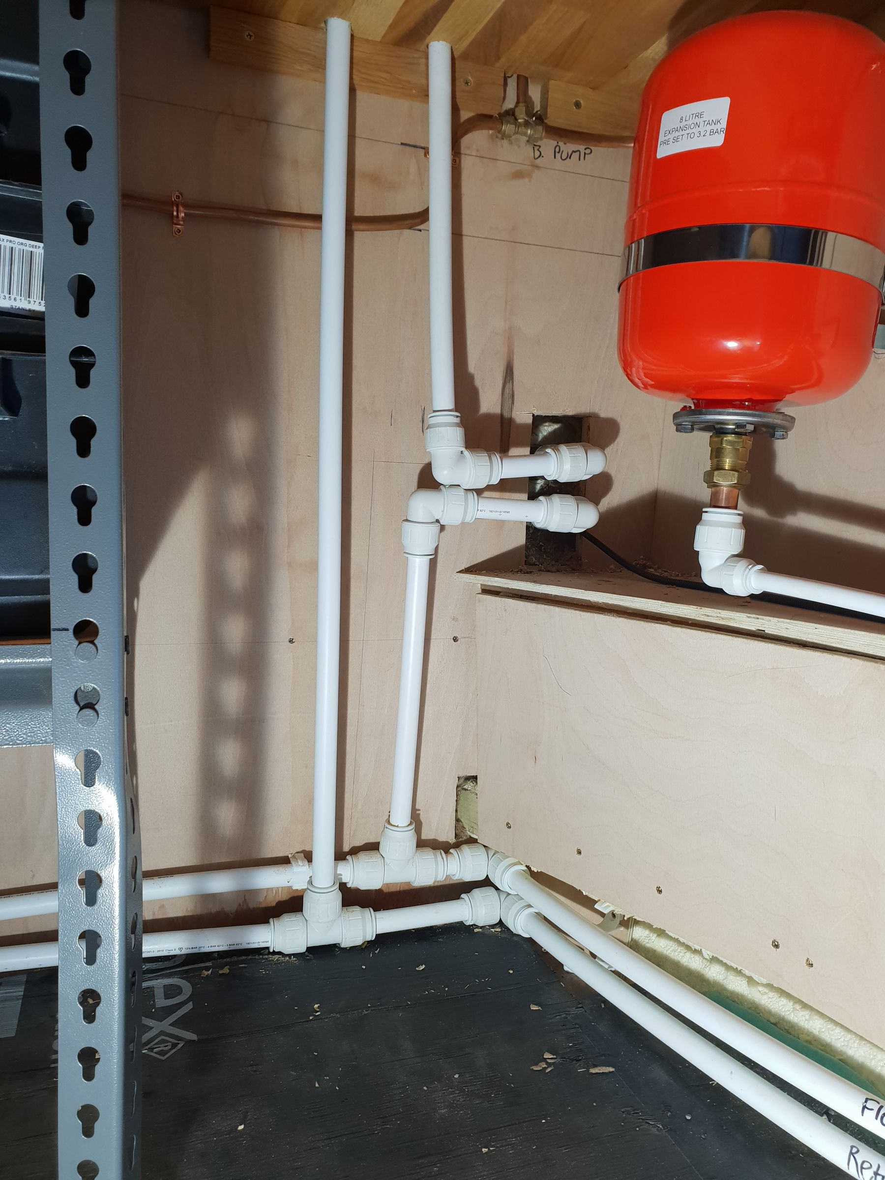
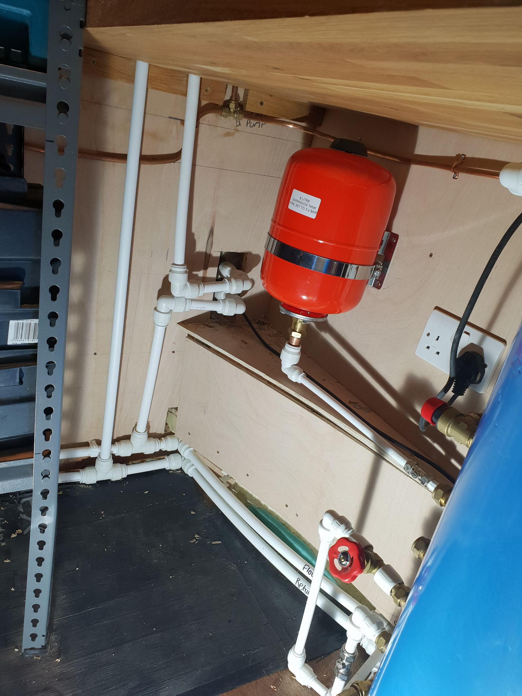
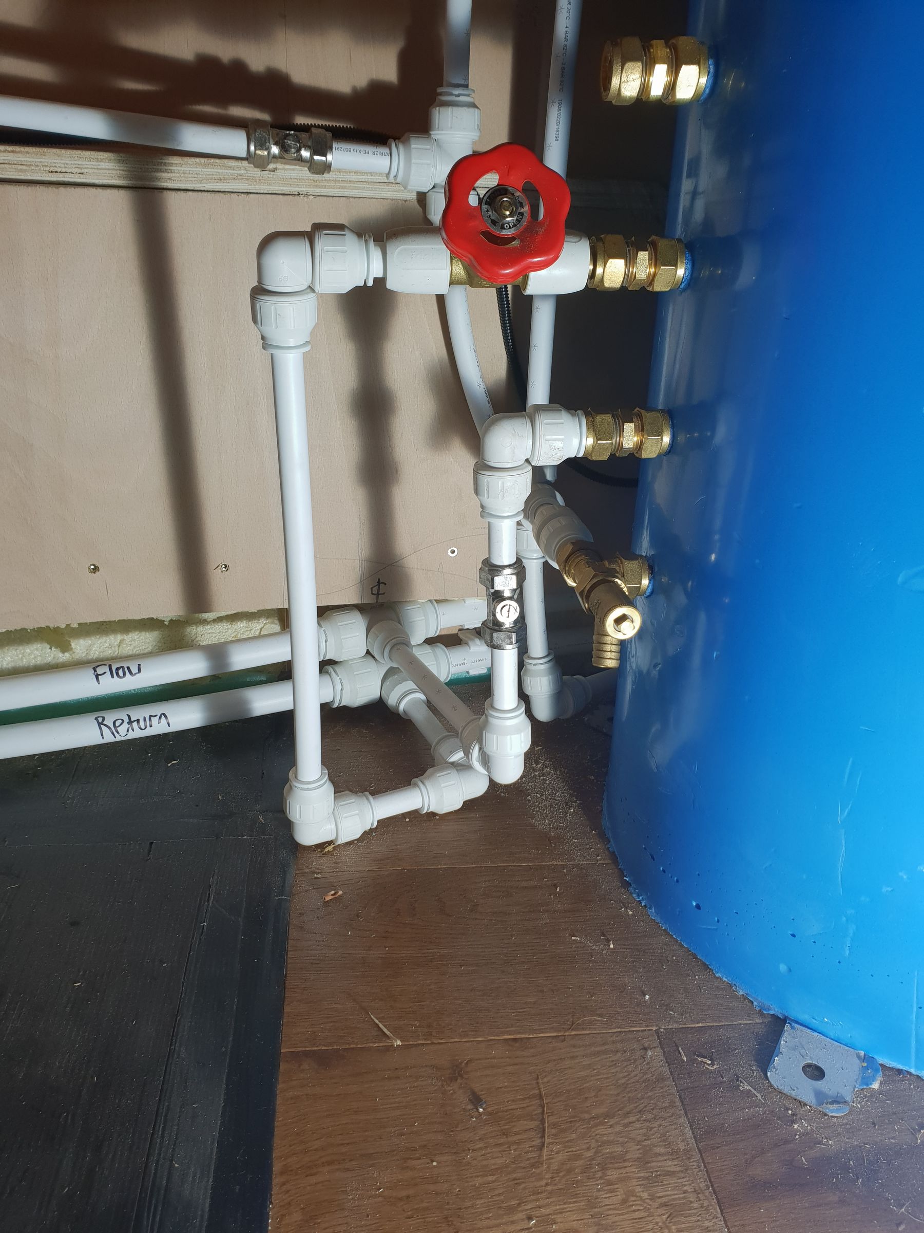
It's quite untidy down here but it's not my priority at the minute

-
I worked out that the 22mm pipe work alone would hold something like 12L. 55 surprised me I was expecting 40ish. There are three double Rads, the calorifier (75l) coil, the header tank etc. Lots of areas for antifreeze to fill. The boat is 57x10 ft
Feeling optimistic about this new bleed valve. Is there any particular valve which would be best?
-
3 minutes ago, Mike the Boilerman said:
Yes, this exactly. A water pump will pump water but not air. As soon as air from the calorifier loop arrives at the pump, water flow stops and the Eber overheats. This is what several of us here think at the moment.
So why would the air keep making its way back to the calorifier once the pump fails to get going, instead of staying up at the pump?
Do I need to drain the 55L of antifreeze from the system, then flush through with water, then top back up with the coolant?
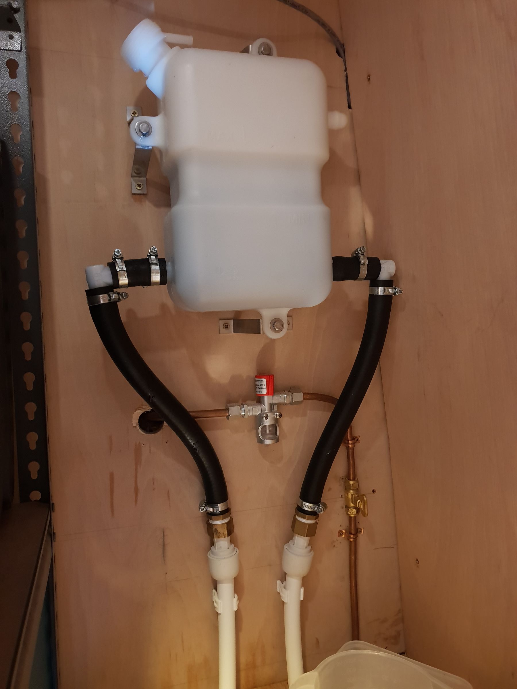
Just now, Chewbacka said:It might help if you gave us a general photo showing the heater, pump and inlet side pipes as it feels that the pipes might run downhill to the pump, so when the pump stops air rises back up the pipe away from the pump ready to come back down on the next start attempt.
Answered my question before I had typed it. Will send one over this evening.
-
26 minutes ago, Mike the Boilerman said:
That might well be enough to get it going. Once the pump finds a circuit to pump around, the Eber will prolly work properly and push other air out into the rads where it can be bled out.
What do I need to do once I've fitted the bleed valve? And why would the air go back to that point? Do we think there is air in the coil which keeps being pulled through to the heater?
-
6 minutes ago, Mike the Boilerman said:
Replace the top elbow just to the left of the red-handled gate valve with a tee, with the spare branch pointing UP, and put an air vent in the UP pointing bit.
Brilliant, thanks Mike. I'll pick the bits up on my way back from work.
-
2 minutes ago, Chewbacka said:
I noticed in your photo of the coolant header tank there is another job for later - for an lpg bubble tester to be an acceptable bss method for lpg leaks it must be in the gas locker. Assuming you wish to use it for that purpose needs relocating.
The gas locker is just the other side of the bulkhead. I was advised that it would be fine here and the bss seemed fairly vague. Will move if needed before I get the bss.
-
8 minutes ago, Mike the Boilerman said:
This photo alone jumps out at me as illustrating the installation has not been carried out with any appreciation of air locking. There is no air vet to let the air out of the calorifier coil so this circuit is never likely to work unless the pump happens to have the power to shove the water through and clear the air.
I note OP is on the K&A and so am I. Happy to call in for a quick look and see if I can pin down the problem if the OP wishes, and is anywhere near me the Hungerford end, rather than Bristol!
I hadn't considered air being trapped and thought it would always make it's way up to the header tank.
Where would I put a bleed valve on this pipework to help bleed the coil?
-
9 minutes ago, Tony Brooks said:
Straight away I cans see an air trap with a sloping pipe to the left of the expansion tank and have a suspicion it may be the cold feed to the boiler.
Thats the hot water pipe coming from the calorifier, not part of the radiator system. I don't seem to have any air trapped in that system, possibly because the expansion tank holds pressure?
-
I am struggling to draw out the plumbing but that's the brains of it. The Rads just tee of the flow and returns.
Where the pipes run off to the left of the photo (starboard) they are feeding a small rad on the bulkhead.


Struggling to get the Webasto Top C to start up.
in Build Blogs
Posted
Just for the record, I've got the circulation pump connected to the 12v fuse board and wired completely separate.
This allows me to use the Webasto as a functioning heater. It's only a temp fix until the refurbisher is back off his holiday so he can send me a new wiring loom (he thinks this is the issue). Will update once the new loom turns up.