Erik.narrowboat
-
Posts
73 -
Joined
-
Last visited
Content Type
Profiles
Forums
Events
Gallery
Blogs
Store
Everything posted by Erik.narrowboat
-
Would you mount the VSR in the electric cupboard (where the master switches are) rather than in the engine room, where it currently is? Or did I misinterpret? I was hoping to get rid of some wire because especially around the master switches it's very messy and there is not much space to even run new wires through. But I'll leave that for now as any errors will cause more problems.
-
Btw, I spend much of the weekend cleaning the engine with degreaser (just for kitchens, yellow spray bottle) and it has helped quite a lot in removing dirt and making all parts visible. Shall I use this on the wires as well?
-
The advanced controller has some very thin wires (1-2mm including the harness) coming out of it but does not really seem to be connected to anything. The master switch you see here is the same one as before, there is one for domestics (top) and one for the engine (below). Ideally I would remove all the redundant wires and other redundant parts so it would be easier to see what is there, but this would require identifying what is redundant. I reckon this would be very difficult to do through the forum. However, if there are any parts that I can certainly remove that would be great as there is now just a lot of wire obscuring what is important. Your diagram is very useful for identifying which are the main connections between batteries, ignition and engine and I think I would be able to do this. I understand it does not represent the entire boat. Regarding the last paragraph, what exactly do you mean when you say 'start the charging circuits again'? Does that mean replacing all the wires? The information you and others have provided is really useful, I think it should be enough to work it out. I am just trying to be as sure as possible of what I am doing before I start hence the last questions. Hopefully I can give this a go next weekend.
-
It has a BMC 1.8. is/was Harborough marine a good boat builder
-
https://canalplan.org.uk/boat/66789 It's this boat
-
Forgot to include the photo I'm now away running some errands but will measure the voltage when I'm back It is, how can you tell?

-
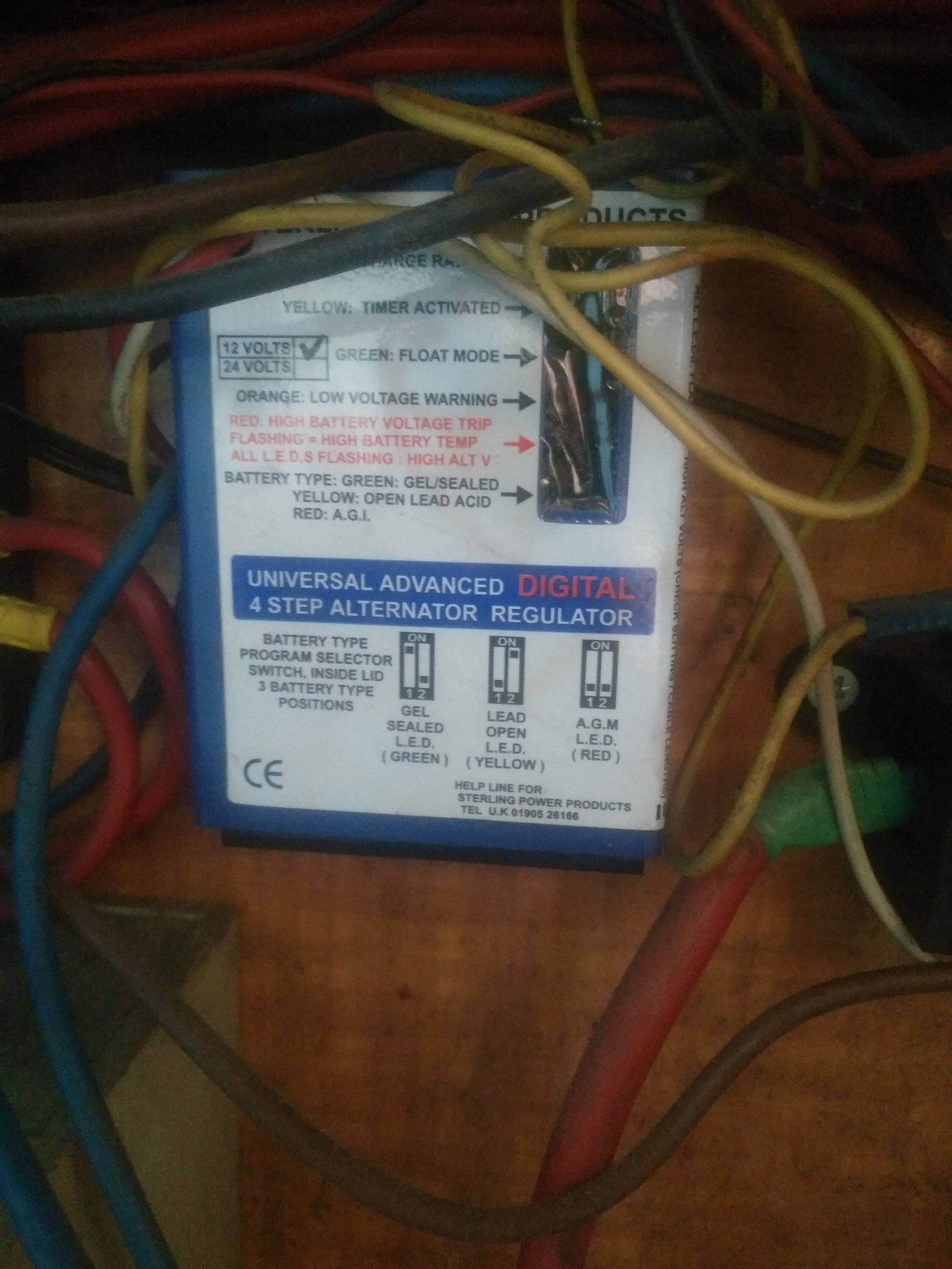
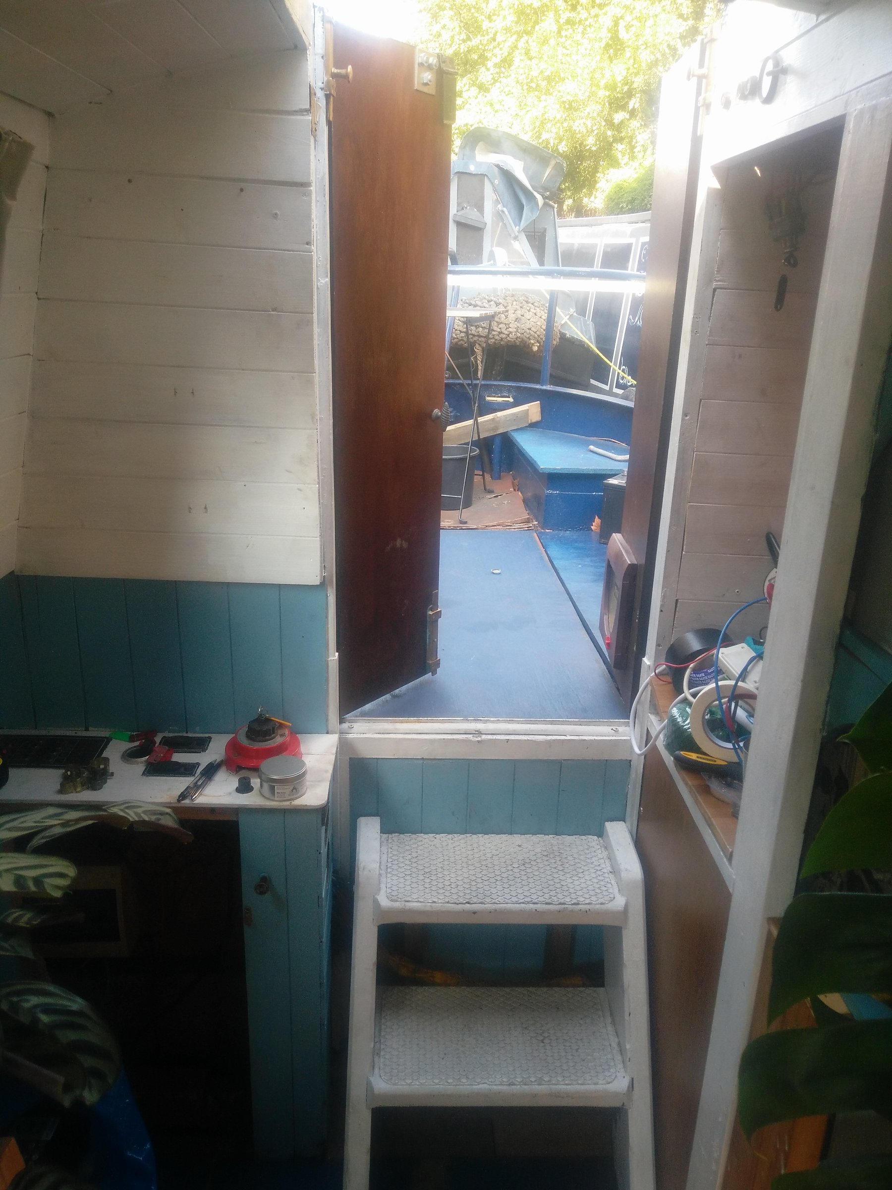
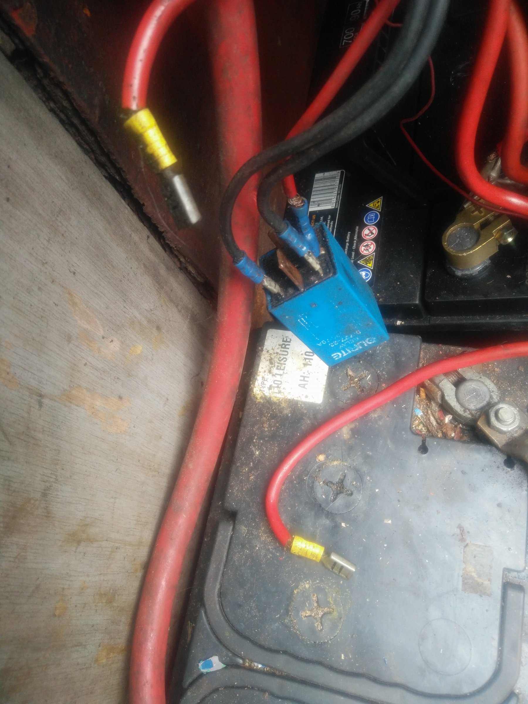
Thank you, this is great. I have been trying to identify each of the wires. I have no doubt your diagram is correct, but there are obviously a lot of other wires plus the wires that go to the ignition ate no hidden behind panels and are wrapped together so I can't trace them. I have added a photo (first photo) to show where things are. It's not a great photo but what you see it the electrics cupboard on the bottom left and the ignition on the to right. Just to give an idea of why I can't trace the wires to the ignition. I was also wondering if the bus bar you are showing is the existing one or a new one? I have taken a photo of the panel above that the wires on the bus bar connect to (photo 2). I found another relay (photo 3) that connects the engine and domestics master switches and has two more wires that go to the bus bar and possibly the ignition. It is 120 amps. Could this be the one in your diagram going from the engine master switch with the text 'feed to ign switch - should be fused at 50 amps'? The wire with a red X seems to be connected as you said. There is also an alternator regulator they connects to the bus bar and possibly the ignition. I hope this makes sense. I'm just trying to comprehend all the information before starting to change anything. I am debating whether I should try to do it myself or pay someone to help with the right instructions. On the one hand I hesitate to try myself as there seem to be some dodgy connections, on the other hand with all the great support here I feel it would be more satisfying and also a good exercise to do it myself. Having knowledge of the systems on my boat will surely not hurt.
-
Thanks for the feedback on the diagram and photos. Tomorrow I will double check what I have drawn (though I have been careful to follow the wires) and add the alternator. The source/selection master switch may be there because the boat used to have a shoreline? Does that make sense? Regarding the relay being connected to a positive and a negative, what should it be? Only negatives, or only positives? If I were to replace the thick wires I would have to get the tools or help from someone to do that. Do you have any recommendations on where I could buy tools and wire? I went to a hardware store yesterday but they had a limited selection of wire.
-
I have connected the engine battery negative to the domestic battery negative. I measured again the terminals in the relay. Voltmeter negative on engine battery negative: Pin 1: 0.6v Pin 2: 0v Pin 3: 0.6v Pin 4: 0v Pin 5: battery voltage (12.6v) Voltmeter negative on domestic battery negative: Pin 1: 0.6v Pin 2: 0v Pin 3: 0.6v Pin 4: 0v Pin 5: battery voltage (12.6v) This is without the ignition or engine on. I also insulated the wire that was on terminal 4. I drew a (clumsy) diagram of the connections. Can draw a cleaner version on the weekend. In the diagram on the bottom from left to right (in black) you see the engine with the starter motor, engine battery, domestic battery, inverter/charger (see first photo), bus bar (second photo). From left to right in red you see the starter motor, starter battery main switch, domestic battery main switch and a large button which I'm not entirely sure of what its function is (third photo). On the top, what I named switchboard is the panel with the warning lights and ignition. I hope this makes any sense. I will draw a more near version when I have time. Perhaps there are more connections to investigate and include. Tony, please let me know if you want me to send you the photos by email as well
-
That is definitely a good point. I am planning to buy the wires that Tony described and will also try and replace these. I reckon if I replace them with wires of the same thickness and colour it should be no problem?
-
I will connect the negatives poles of the domestic and engine battery then and continue with the steps you described in your post on Tuesday at 21:11 I will also insulate the black wire as you said. I am happy to follow the above order.
-
Yes, it is the master switch for the engine battery. There is another one right above for the domestic batteries. I had hoped to make better photos and sketch a diagram of the connections but inside the cupboard it was already dark and hard to see anything. I'll try doing it tonight or otherwise on the weekend when I'll have more daylight hours. The bus bar/junction box seems indeed to be for the domestic circuits as they all come from that side. The batteries weren't linked previously and the electricians didn't say anything. I'm afraid I have misinterpreted them being linked as being linked to a negative, not to each other necessarily. I will link them and see measure again voltages on the relay. Are there any other tests that I should repeat? I'll read through the instructions as well when I'm home to see if I see any.
-
That is correct. Just wondering, did you conclude this from the test or from the photos?
-
I just tried tracing the wires from the relay and subsequently measuring if there is any current on them. Tracing: Pin 2: to engine Pin 5: to cupboard, where it meets starter battery positive (first photo, the lower bolt has two thick red wires, one is coming from on 5, the other from starter battery positive) Pin 1: to cupboard, from there to ignition panel. A lot of wires are taped together so it's impossible to trace further Pin 3: to cupboard, see second photo. It sits on the screw second from the bottom, on the left Pin 4: I can't tell where it goes. I then went on to measure with the voltmeter with ignition on but engine not running. Negative wire on the engine, positive on the relay: Pin 1: 3.8v Pin 2: 0 Pin 3: 3.8v Pin 4: battery voltage (of starter battery) Pin 5: battery voltage (of starter battery) Negative wire on starter negative, positive on the relay: Pin 1: 3.8v Pin 2: 0 Pin 3: 3.8v Pin 4: battery voltage (of starter battery) Pin 5: battery voltage (of starter battery) Negative wire on domestic negative, positive on the relay: Pin 1: 0 Pin 2: 0 Pin 3: 0 Pin 4: 0 Pin 5: 0 Should I repeat the test with the engine running?
-
Yes, that is what I meant. Which option would you recommend? I will go with what you think will be the best solution. Buying the parts is not an issue.
-
I am a little bit confused as to whether the message I wrote yesterday had displayed correctly. I was having some issues uploading an image. I will post it again below. To answer to your message. 1. Sure, I will wait. 2. That is correct, I have but been moving wires with the engine running, other than those from the voltmeter. 3. I have taken off the to large blades from the relay and then, after starting the engine, made them touch. The image below shows the two thick cables disconnected. If this photo is not clear enough (it was meant to show the wires), I can take a more close up one of the relay when I get home. Should I order the relay you have shown or wait?
-
I meant the wires from the voltmeter. Sorry if that was unclear.
-
I have insulated the D+. I noticed the other wires are corroded and also quite dirty. Do you think this might have an effect? Voltmeter across domestic battery reads 0, with engine off and with engine on. To be sure I moved the wires to the engine battery with the engine running and that still measured 14v, meaning the alternator is working. I then moved the wires back to the domestic battery and connected the two thick cables from the relay, but the reading showed 0v.
-
The domestic bank reads 0, when I hold the meter between battery positive and the pin it still reads 0. The wires from the alternator are connected to starter battery positive. They were previously on the domestic bank but since that is flat another electrician moved them here. Voltmeter between clean metal and pin with ignition off gives 0 volt. With ignition on it gives about 2 volt. I have attached two photos. One shows the starter battery positive with two thick red wires from the alternator connected. The other shows how the domestic bank is wired. Both positive and negative go to the electric cupboard, separate from the starter battery. I have bought a new domestic battery because I figured I would need it at some point. Should I install it and repeat the the first test? I will also send you the photos along with previous ones by email.
-
I have gone back to the first step and test the alternator with the wire. With the voltmeter attached to the starter battery it reads 12.6 volt. As soon as I start the engine this guess up to 14v. Holding the wire against the battery and the pin that suits through the blue quite still makes it read 14v so no jump. I have printed all of your instructions and read them about five times. I'm trying to follow them closely. I apologize for jumping ahead previously. You mentioned that looking at the photos makes you lose work, is there a way I can make it easier to read/watch my comments?
-
Sorry, I'm writing all of this from my phone. It's a but hard sometimes to spot mistakes of the post is very long. It was meant to say engine/oil temperature. If I'm correct that's what it is measuring.
-
There are a black and a red wire on the back of the warning light. Both give battery voltage. The black wire is sitting in the female blade with another black wire that connects to the engine temperature meter. I did not want to take out the wire and replace it with a new one connecting to the D+ in the alternator before knowing what to do with that other wire so haven't proceeded with that step yet. I apologize for jumping back and forth, I think I need to get clamps so I can complete the missing steps before moving on.
-
There is indeed only one cable that is at battery voltage ah the time. I can't test the different key position as I can't hold the wires of the voltmeter in position while turning the key. I reckon I should but clamps? This also prevents me from testing the alternator with the extra but of wire as I would have to have the voltmeter stay connected to the battery while manually holding the wire.
-
Yes, there seem to be indeed 4 different position. Position 1: off Position 2: with the key turned only about 1/8th but status in position. The pool temperature meter comes on. Position 3: again just about 1/8th. The key guess back to the run position when let go. No lights. Position 4: engine starts. No lights. I was indeed not doing it with enough finesse, although I think the Sirius are probably quite worn as position 3 and 4 are very hard to distinguish.
-
No