


jetzi
Patron-
Posts
1,179 -
Joined
-
Last visited
-
Days Won
1
Content Type
Profiles
Forums
Events
Gallery
Blogs
Store
Posts posted by jetzi
-
-
7 hours ago, PD1964 said:
The flight is so unkept and becoming a mess, considering there has been 2x resident lock keepers there for years it’s laughable, what are they paying these people to do all day when there is no boat movement most days.
I think you're being a little hard on them judging by those images. It's just a little vegetation, the blocks are still well proud. I wouldn't look twice at a lock like that, it's hardly a hazard.On 14/10/2021 at 12:26, Jen-in-Wellies said:£800k as a low estimate. Probably over a million in reality. That is quite a few sets of lock gates.
It's really tragic. I think what makes it so much more tragic is that it's not just wasted money, it's that anyone with any taste at all sees the blue signs as a blight on the old infrastructure. But the signs DO stand out and that's what they are for.
I reckon it's a branding exercise for them to try to raise funding from donations, because that initiative was such an abysmal failure. And completely unsurprising IMO. The public doesn't realise that the canals are managed by a separate organisation, I certainly was oblivious before I started boating.
Perhaps cart is counting on awareness being enough to get people to open their wallets, but I have no doubt that any future initiative would fail spectacularly as well - even if people know that cart is a charity. Public space kind of feels like it ought to be free. Cart is counting on people caring more about them than the other 1000's of charities with objectively more worthy causes. It just isn't going to happen no matter how many sinking tyres they display around the network.
-
Speaking of maintenance and a shallow canal, there's now an apparently stoppage on the HNC between locks 8W and 21W due to a major leak just below Roaches lock (15W). https://canalrivertrust.org.uk/notices/20822-lock-8w-to-lock-21w-huddersfield-narrow-canal - anyone in the area got any idea how serious this is? Is the canal totally dry?
According to their updates, they started repairs today and will give us an update on Tuesday 19th October.
One thing that I must give cart credit for is their updates with the stoppages, so with baited breath I wait for Tuesday's update..
-
8 minutes ago, nicknorman said:
So the general idea is to leave it on slow and 50% SoC when in the Marina, either unoccupied or with us on the boat. If we are going to go cruising, we can set the switch to fast a few hours before and maybe to 80% or 100% SoC so that we set out with well charged batteries.
Sounds great. Any desire to connect the BMS to the internet to allow you to set the combi to fast charge if you are not on the boat? Can imagine that would be useful so that the battery is full by the time you arrive ready for your cruise. Perhaps would be nice to be able to monitor the SoC remotely as well.
-
2 hours ago, Tony1 said:
f a high current really does prevent the Victron BP from actually doing what its been purchased to do, that will be very disappointing and annoying...
Yeah, it seems weird to me too, but they do specifically say not to use it for inverters. It could just be Victron covering themselves, it seems very strange to indicate against the very thing the device is supposed to do.
The bit about it not being able to handle "reverse" i.e. charging current is more serious though IMO as this is an "everyday" situation rather than an emergency one. Unless you are only using the BP to terminate the load circuit, in which case I'd probably ignore it, especially if I already installed one.
2 hours ago, Tony1 said:I do take your point about 12v being a bit close to the edge, which is why I'm looking more at 12.5v myself (although in terms of SoC, those correspond to 9% and 14%, so not a huge difference.
Yeah, many folks on here subscribe to the 80/20 SoC rule which is probably a bit conservative (considering that, with only 60% of your LiFePOs now usable, makes them roughly on a par with the 50/50 rule people follow with LAs).
I actually had the same problem with the voltage pulldown shutting off my system. I mostly solved it by adding more cells, but ocassionally I'll get an alarm when I try to do something high-current with a low SoC. Another point for a microcontroller system, you could add an ammeter and build in some allowance for a lower voltage when under a high current situation, at least for a few minutes.
2 hours ago, Tony1 said:The valence batteries dont have any self-disconnection function. If you do feel it is necessary - and to be fair, there are long term users who have no disconnect and have had no problems), then you must set it up yourself.
After a few early near-misses during charging, I decided that I did need both high and low voltage disconnects, and initially I did both using a single BEP switch.
1 hour ago, nicknorman said:Valence internal BMS doesn’t do disconnect. You can allegedly get a separate bit that does the disconnect in communication with the internal BMSs, but it seems hard to come by.
Ah I see, for me the emergency disconnect on per-cell over/undervoltage is the most important bit of the BMS. So really the internal BMS is actually just doing some on-the-fly balancing? I feel automatic balancing is a very optional extra, I am not going to bother with any of that, instead I just consider an annual manual top balance as part of boat maintenance.On 12/10/2021 at 22:48, MtB said:Many BMS boards claim to balance the cells too but they never explain how they do this. Top or bottom? Never explained, or how in detail. All that is generally claimed is "active" or "passive" balancing.
My understanding (probably wrong) that it's neither top nor bottom balancing, instead it's just on-the-fly balancing at whatever voltage the cells happen to be at. At least that's how I think the ISDT balancing works (my only experience of such a function), but this is triggered by a button so I suppose you could use it to top balance if you are very patient and don't mind holding your battery at a high SoC for the duration!
1 hour ago, nicknorman said:when I was developing my BMS, I too got some AA lifepo4 cells. With an Arduino etc, you don’t need pull-down resistors, you just configure the outputs as normal outputs and they actively both pull up and pull down. If you are using a 3.3v Arduino and want to drive a MOSFET directly, you need to select carefully. Mosfets are a bit funny in that at a medium Vgs, they appear to have low on resistance but if the current gets too much, the resistance increases a lot. So if you are planning to switch fairly high currents, you need to check the data sheet carefully.
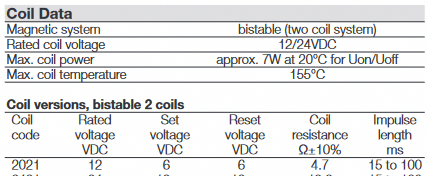
Alright, that's good to know. According to the docs the D-pins on the Arduino Uno are "on" at >2V (to a maximum of 5V) so I think it must be a 3.3V device. I'll only be switching Tyco BDS-A relays with the MOSFETs, so I can spec them all the same. According to the Tyco BDS-A data sheet the max coil power is 7W (~0.6A at 12V) and resistance is 47Ω, though you mentioned some time ago that the Tyco coils take a burst of say 10A at 12V (36W) - not sure if this is right but I will overspec the MOSFET to the higher figure just in case.
.
Still reading around what all the various MOSFET specs mean, but so far I think the one I linked to earlier would be suitable for this application. They can manage a pulse of 32A which is plenty to operate the coil. The Vgs threshold is 2-4V, so that seems correct for the Arduino outputs (would like to find one that was 2-5V to match the Arduino output exactly, but they don't seem to exist [edit: on second thoughts, I think I'm reading this wrong - I think 2-4V means that it requires a value of 4V to be fully on - so I think I need to look for a MOSFET in the range of 1-3V]). The gate-source maximum voltage is +-30V so that should be able to cope with the highs and lows of the system (though if the Arduino is outputting 30V, something has gone horribly wrong!)Considering that the MOSFETs are so cheap, I see no reason not to overspec them for safety, but I am still trying to get to grips with how they work to make sure that it's not counterproductive.
-
On 12/10/2021 at 17:01, Tony1 said:
That plan leaves me short of a low voltage disconnect, so the other part of my cunning plan is to get a victron battery protect to do that job, as Richard suggested.
Fair warning, I remember while setting up my system I had the same cunning plan to use a Victron BatteryProtect, and I remember reading stuff that cautioned me off it. I recall two main reasons, 1) it doesn't liking shutting off during high current i.e. from inverters, which of course is exactly when you're likely to run out of juice; and 2) Victron say it shouldn't be used with reverse (charging) current "The BatteryProtect is not designed for reverse currents from charging sources" https://www.victronenergy.com/battery_protect/battery-protect
On 12/10/2021 at 18:31, Tony1 said:But 12v is about 10%, which is the point I'd want to disconnect, so maybe somewhere between 12 and 12.4v.
The thought of 12V makes my palms sweaty. My emergency cut off when any cell drops below 3.0V, which means 12V if the cells are perfectly balanced, which they aren't, in practice I never let my battery drop below 12.6 or so.
On 12/10/2021 at 18:25, MtB said:I know it's a bit late in the day to question this, but surely you (everyone) should be monitoring individual cell voltages, not the whole bank voltage. It is perfectly feasible for one cell to get too low (or high) yet the whole bank voltage remains above the chosen emergency disconnect voltage.
I think most of us are monitoring cell voltages for emergency shutoffs (at least I should be, but my system is not working at the moment - instead I'm relying on the overall voltage, very conservative battery use, and using the ISDT-BG8S for a low voltage alarm - it doesn't do high voltage unfortunately so I have to be extra careful while charging).
But the chargers (MPPT or smart alternator for those who have them) and in some cases the first load disconnect is handled by the overall battery voltage. Which is actually fine as long as the batteries are balanced, similar capacity and you don't set the cutoffs too low and too high. I am not sure how the valence batteries work, do they have an internal shutoff relay for the whole battery when one of the cells drops below a preset voltage (or rises above a preset voltage)? How much current can the internal relay handle?On 09/10/2021 at 20:03, nicknorman said:yes I hadn’t noticed that the BMS only had an option for a negative-going pulse. In that case you need to use a P channel mosfet and connect it as you proposed. It’s not clear whether when BMS’s pulse to ground is not active, that output is floating or pulled up. In any case I’d add a pull up resistor from gate to battery +, so that the MOSFET gate returns to source voltage as soon as the pulse stops.
Tyco do specify a maximum pulse of 100mS but if it’s going to be infrequently operated than with a bit of luck it will survive 150mS. But you definitely want that pull-up resistor to ensure the pulse stops ASAP.
After some deliberation, I've decided not to continue to pursue the off the shelf cell performance monitor "BMS" approach. Now that I have some idea how MOSFETs work instead I am experimenting with an Arduino based system, using logic-level n-channel MOSFETs with pull-down resistors. I'm much more comfortable with software than hardware, and this will allow me to extend the BMS to include temperature sensors and a battery heater along with a relay for my dump load. I'm also buying a few small capacity LiFePO4 cells (14500 "AA" form factor) to test with. I'll get the parts I need in about a month. If I have any luck with this I'll post my solution for critique!
-
On 12/10/2021 at 15:20, Alan de Enfield said:
(40 years of Narrow and Wide boating on the sea, the canals and the rivers., I have nothing against anorexic boats, they are perfect for what they were designed for, and hopeless in other areas for which they may be unsafe. Fat-boats are perfect for the wide deep commercial Canals and Rivers and a 'disaster' on the narrow canals).
Fair enough. My experience of broad canals is the GU, Lea&Stort, part of the T&M, L&L, and K&A in pictures. I'm not sure that I'd class those as "wide and deep" at least not for their full lengths. I have seen many, many widebeams moored up but very, very rarely seen one moving. In fact, though I'm sure there have been others, I can only recall a single time I passed a widebeam in the last 3 years, I remember because it was unusual! I'm a continuous moorer myself though so it might just be that I myself don't cruise that much.
On 12/10/2021 at 15:22, peterboat said:And thats on a navigation made for wide boats
Exactly. Rightly or wrongly, I get the sense that widebeamers are resented by everyone else, whether the canal is a broad canal or not. It might be a "reverse classism" thing, it's fashionable to despise the wealthy. I don't feel that way, for the record, I haven't ever been inconvenienced by a widebeam.
7 hours ago, IanD said:if you like the Dutch Barge look but have vertical sides with 200mm gunwales to avoid the bridge/tunnel problem, you pay for the look by having even less room inside at shoulder width than a conventional narrowboat
I'm going to keep an eye out for the bridge/tunnel problem in the future, because I do like the Dutch barge vertical sides and would consider one in the future (though wouldn't be willing to sacrifice interior space for it). I haven't noticed any bridges that have been tight at my cabin corners, though having said that there is a large dent on one cabin corner where my boat met a bridge, probably back in her hire days. So I'm probably just oblivious.
-
4 hours ago, Midnight said:
Today I spotted two lockies replacing what looked like perfectly good black and white lock signs with new black and white lock signs but with a sunken tyre logo instead of a Swan. I asked why no blue signs lockie says "I don't like blue". That lockie should be the next Chief Executive of CRT.
The black and white signs can look quite smart, at least on those rare occasions when the signs are useful. -
1 hour ago, Alan de Enfield said:
It is surprsing what those few extra feet in width from an 'anorexic-boat' can make. Life is so much more comfortable, if you are happy with restricted (just 1000 miles ?) of cruising there is no reason to go 'skinny'.
I don't doubt that a widebeam is much more comfortable, but it is also much more expensive in a lot of ways. And surely they are much harder and slower to navigate - I very rarely see widebeams moving anywhere. I think I'd feel in the way - whether it's valid or not I feel like a lot of narrowboaters resent widebeamers, take this encounter on the K&A where these vloggers were abused simply for having a widebeam.
Just now, David Mack said:Water can come from any number of places. Can you guarantee that your vapour barrier, floor covering and the join between them are 100% watertight for the life of the boat?
Most people's cabin bilges are bone dry. And that is because there is an air space and some (limited) air movement which allows the bilge to dry. Put floorboards directly in contact with the bottom, and any damp down there will stay for a long time.
Fair enough. Was really just considering the logical extreme of maximising interior height. Was thinking you could save an extra 3/4 inch by not needing a board substrate to your floorboards. Most boats have plenty of headroom for me anyway, a thick baseplate with minimal bilge space is probably the best answer then.
-
27 minutes ago, IanD said:
Minimal tumblehome not only looks a bit ugly (if you care about that)
It's a bit of a matter of opinion, personally I find the dutch barge style much more attractive.
27 minutes ago, IanD said:more likely that you'll scrape the cabin under narrow canal bridge arches
Yes, but this is also (mainly?) a consequence of air draft, so if you have a thick baseplate, fairly deep draughted, minimal height bilge, and keep your interior height to a minimum, then hopefully won't be too much of an issue. We're only talking about a couple of inches wider at cabin roof height, right?
30 minutes ago, IanD said:The tall cabin prow pushed right forwards doesn't give you as much extra usable space inside as you'd think because the cabin (and hull) start to taper in well before this, and so does the space inside
So you push the king size bed as far forward as you can and put your water tank, generator or gas locker above your head. You would then be able to get out of the sides of the bed about half way down the bed.
I don't know, again it's a compromise I guess.
33 minutes ago, IanD said:The reason many people on conventional boats want a well deck is either for quiet travelling (away from the engine) or extra storage. With a reverse layout boat the alternative is to make the stern (semi-trad or cruiser) the place to be when travelling, but unless you have an electric boat you don't get away from the noise like you do in the bows.
I think another reason is for outside space. I feel like having outside space at both bow and stern is wasteful. I have a cruiser stern and it's still the place to be when travelling despite some noise from the engine. It's not loud enough to drive anyone off the stern deck but an electric boat would be nice! A cocooned diesel genny under the stern deck surely would be a hell of a lot quiter than a diesel engine in a hollow engine bay under your feet, anyway?
-
4 minutes ago, doratheexplorer said:
You don't need to put your feet down at the side of the bed at all. You get out at the foot of the bed. You can then have a ridiculously wide bed if you want. Like a bigger version of the beds built into the bows of small GRP cruisers. This is actually an easier set up for couples than most narrowboat beds since nobody has to clamber over anyone else to get out. It's what I'd have if I were the OP.
The main downside is that you can't walk straight through to the front deck, you can only have an emergency hatch above the bed. I'd only want it with a cruiser or semi-crusier stern. But if I was having a bespoke boat built, this is what I'd have.
Same here. What I'd really like is a "dutch barge style" narrowboat, minimal tumblehome, with a vertical and very tall prow - I think that this design looks the nicest when you have the cabin as far forward as possible at the expense of a well deck, and it would maximise the internal width. But I'm far too narrow minded to consider anything more than a 6'10" beam.
-
22 minutes ago, David Mack said:
Where would any bilge water go?
Well, where does bilge water come from? Condensation and leaks (hopefully above-waterline leaks!), right? So if you have a vapour seal between your interior fitout and the steel hull, there shouldn't be condensation on the inside of the hull. And if you do get water inside the inner lining, then it will end up on the floor to be mopped up. I guess what you're driving at is that you definitely DON'T want water underneath such a floor! And I agree. But my cabin bilge stays bone dry (can't say the same about my cruiser stern engine bilge, which is really my on-board paddling pool).
26 minutes ago, David Mack said:how would you attach the floorboards? Screw them down to the bottom plate?
If you're laying tongue and groove type laminate flooring, cutting it to the correct size and laying it flat on the floor without any fixing should be fine, right? And if not, what about glue?
I'm just musing really... my bilge is about 4" of air and ballast, and I'm just wondering if it's really necessary in a properly sealed boat.
-
4 minutes ago, IanD said:
A thicker baseplate means less ballast is needed, so less of a gap under the floor. However the difference is nothing like as big as Alan makes out...
If you replace a 10mm baseplate with 15mm, the extra 5mm of steel weighs about as much as 15mm of ballast
Very interesting and makes complete sense. Thanks. Dumb question probably, but is a cabin bilge really necessary - if you were to use a very thick baseplate, say 15mm or even 20mm, could you not just lay the floor directly on top of the steel and forgo ribs entirely? (correcting any list or trim issues with the potato weights Alan mentioned).
6 minutes ago, IanD said:As explained above, you can easily get a full-width double (4'6") in lengthways (any length you want, the Napton boats have 6'9 long mattresses) in a reverse layout, a 5' king-size gives very little room to get past the bed but isn't impossible.
My bedroom is in the centre of the boat, and having quite thick insulation behind the walls and a radiator in the corridor next to the bed, an extra 6" of bed would be very awkward to have to shimmy past multiple times a day. My next boat will have a bed in the bows. Preferably full width, but I guess that getting in and out at the foot of the bed would probably get tiresome! Boat layout is always a compromise... unless you have a widebeam I suppose, to the OP's point!
-
2 minutes ago, Alan de Enfield said:
It means that the floor can be substantailly lower because the need for loose ballast (concrete slabs, pig-iron etc) is minimised to only needing to counter-balance any furniture and fittings, and, that can generally be achieved with one or two 56lb 'potato weights' in the bottom of cupboards or under the bed etc.
The weight of the 13mm base plate is (virtually) sufficient to ballast the boat correctly.
The floor of my boat is laid directly onto the ribs, so how does it help to have less ballast? Wouldn't that just mean more space in the bilge?
Or do you mean, knowing that you need less ballast, you can make the ribs shorter to accommodate less? Most but not all of my bilge has concrete paving slabs in it. -
17 hours ago, Alan de Enfield said:
We had a narrowboat with a 13mm base plate which meant the interior floor could be at least 6" lower than normal
That's really interesting, why is that? Is it because the base plate is thicker, it's stronger and therefore you don't need as tall ribs? Or is it a ballast thing? I notice a lot of people seem to be going for thicker than the standard 10mm baseplate ("standard" in the case meaning "wot I got")
I'm 6'4" and when I was shopping for my boat headroom was a key factor for me, but plenty of narrowboats were tall enough. My boat has 6'7" of head clearance so I shouldn't have thought it would be that hard to find a narrow beam boat that meets the OP's requirements. Also I am not sure why the beam has anything to do with the length of the bed unless you have a NB and are set on a cross bed? The width of the bed does come into it though, my bed is a "small double" which does make it narrower than I'd like, in fact if I was going for a new build top on the list for me is side hatches and a king size bed, at the expense of bow doors and well deck.Regarding OP's original question about renting a mooring first vs commissioning the build first, I imagine it really comes down to how specific an area you are looking in - if you're commissioning a brand new widebeam build I expect you can probably afford to sit on a vacant mooring for a few months - if you find the mooring best snap it up. But I second what everyone said about going secondhand first, if there's one thing I have learned from a secondhand boat it's exactly what I'd want in a new build (and spoiler: it's very different to what I thought I'd want at first!)
-
 1
1
-
-
2 minutes ago, BEngo said:
Is this a "have to get somewhere "trip?
No not at all. It will probably still be winter, but I can spend some time exploring the Caldon canal if I should wait for summer.
3 minutes ago, BEngo said:The Soar route is prettier than the Coventry. There are now more moorings in Leicester. The stretch out of Leicester can be short of water, and you need to get through Foxton and Watford which are time restricted. Market Harborough and Welford are excellent side diversions.
What do you mean by "time restricted"?
You mention Foxton, and going to see the site of the incline plane is on my bucket list, I'm not sure if most people would consider it worth the visit.
-
That's good to know, I didn't realise rain would be an issue. Is the Soar unnavigable in the rain or merely dangerous? I don't mind getting stuck for a week or three, not in any hurry (I expect the trip to take me 2ish months).
I'm leaning towards the Coventry route, because I'm in a narrowbeam and it will be easier to do narrow locks. I have also heard good things about the Ashby.
However I tend to prefer quieter, more rural, more off-the-beaten-path routes, and I think the GU Leicester has more rural moorings.
-
Going from Great Haywood to Northampton. Already done the Shroppie / Staffs & Worcs / BCN, I'm torn between:
1. taking the Coventry Canal (with a detour up the Ashby) and North Oxford via Braunston, OR
2. taking the longer route via Soar Navigation & Leicester branch.
Which would you recommend? I've not been on either canal and I might not get around to trying the other route so the stakes are high!
-
44 minutes ago, nicknorman said:
These are enhancement mode N channel MOSFETs, and do “low side switching”. You need to connect (fused) battery + to the appropriate relay coil terminal (remembering that the Tyco has freewheel diodes, so polarity is important), other relay coil terminal to the drain, and the source to 0v.
If you connect the source to positive as your proposal, you forward bias the body diode and it just conducts, almost like a short circuit.
Hmm, I don't see how this can be correct. Say I'm dealing with the "Reset" (disconnect) for overvoltage on the "charge" Tyco relay (terminal assignment diagram below, taken from the Tyco BDS-A data sheet)
The cell monitor board provides a pulse of GND (battery -ve) to switch the bistable relay (according to the manual, Umax output #2 provides a 150ms pulse). So with this output (-ve) connected the gate of the MOSFET, I figure that in order to create the voltage differential needed to switch the MOSFET, I would need to connect the source of the MOSFET to the battery +ve.
To reset the Tyco, the relay terminals 1 (+ve) and 3 (-ve) need to be connected to the drain and battery. Since the drain, when the MOSFET is on, connects to the battery -ve via the source, this would go to terminal 3. I would have to connect the other Tyco coil terminal 1 (+ve) to the battery +ve.
I have a suspicion the bit I'm not understanding is in "forward bias the body diode". I figure that all I need to do to cater for the diodes in the relay is to connect the coils the right way around (1 to +ve and 3 to -ve), but I fear there is more to it than that.
44 minutes ago, nicknorman said:select a mosfet with higher Vgs
Yeah, I thought 16V would be plenty because I hadn't considered battery spikes - thanks for that. I was actually mainly looking at the drain/source max voltage (the relay circuit) which in this case was 55V, I will look for a MOSFET with a higher Vgs. edit: perhaps this one, which has a Vgs of +-30V. N-Channel MOSFET, 8 A, 500 V, 3-Pin TO-220AB Vishay IRF840APBF
44 minutes ago, nicknorman said:So you not only have to pull the gate up to some positive voltage to turn it on, you also have to pull it down to zero to turn it off. And fairly quickly
After 150ms, the pulse from the CPM would be over, and therefore send the voltage back down to zero? Or can I not rely on that?
I actually have also just noticed that the Tycos ask for an impulse length of 15 to 100ms, so I wonder if it might be asking too much of the Tycos to handle 150ms... I think maybe the arduino is really the way forward for me.
-
3 hours ago, Tom and Bex said:
There is a commercially available option here: https://www.solar4rvs.com.au/rec-bi-stable-relay-driver-bslrd-for-low-side-swit
Only site I've been able to find it though. This is what I've used with the Tyco relays, not cheap for what it is though. There's also a circuit design on (I think) the Nordik design website.
That does look ideal for converting a standard "normally closed" relay output to drive Tycos. I see they have 2 German and a Norwegian distributors as well? I can't find that component in a search due to it not being in English probably, but someone more invested could see if they could find them.My situation is different as I have a cell-level monitor board which can drive bistable relays, but Nick pointed out that unfortunately that the output of ~1A doesn't provide enough current for the ~3A Tyco coils.
I have been trying to learn how MOSFETs work and I think I know about enough to do some damage. I plan to get six of these N-Channel MOSFET, 30 A, 55 V, 3-Pin TO-220AB Infineon IRLZ34NPBF (data sheet). I will connect each MOSFET gate pin to a board output, the source to the battery positive. Then when the board attempts to pulse switch a relay, it will apply a voltage between the gate and the source and turn the MOSFET on. The drain pin of the MOSFET goes to the relevant relay coil with the other terminal being connected to the battery negative.
MOSFETs actually seems just as straightforward as using a relay, which might be due to my cluelessness! But at just over a quid each and given that my cell performance monitor board isn't doing anything right now anyway, I can't see the harm in experimenting. I may also need to test and potentially replace the various components of the output stages of the board in case I fried something, but maybe the MOSFETs are all I need.
-
1 hour ago, IanD said:
Everywhere else -- meaning, most placers boaters will go in the UK -- 5G uses similar frequency bands to 4G. The total capacity and speed is higher than 4G because of more advanced signal processing (massive MIMO) and increased bandwidth, so it will give higher data rates where 5G basestations are installed -- which today pretty much means only in towns and cities, but will spread out in future.
That's interesting to know that not all 5G is made equal, thanks. The EE coverage map I linked to shows a fair bit of 5G coverage over areas I'm likely to go, and it is expanding. However I realise that it may not be a huge improvement over 4G, I don't necessarily need a huge improvement - some small improvement would be great. For me I think it's worth considering.
I'll check out the routers you linked, thanks. The expensive router does have nice additional features, - for one, it is dual SIM, allowing me to add a second network's SIM card as a failover.
-
16 minutes ago, Loddon said:
In a perfect world I would go for something waterproof which has an ethernet connection out to a separate WiFi inside the boat removing any cable losses.
I actually suggested that on this forum a while back when I was putting in my current system, and I was told that it was foolish to put an expensive router outside. Maybe it's worth trying.
-
1 hour ago, Loddon said:
I find it interesting that you say 4g is not fast enough for video calls. We run 4g at home and have often had two HD video streams running simultaneously, also we run video calls with no drop out. Speed is on average 75+mbs down and 40mbs up often higher down, we are 200mtrs from the mast.
Conversely on our mooring we are lucky to see 5mbs and it does drop out mainly due to the number of users on that particular cell. I suggest that your problem is one of location rather than 4g not being fast enough.
Remember 5g is very localised and not available in most of the country and will be severely affected by the length of any cable between the aerial and router.
I definitely agree that it's mostly about location. I'm a CCer so I am always in a new location. I measure the signal strength with my phone whenever I moor up to ensure that I have reasonable strength LTE or LTE+.
Even at its best, it is just not quite there for me. I can, do, and have been using it for a couple of years now. And it's just a smidge below adequate. For me the problem seems to mostly (but not only) be on the upload - I tend to freeze or my audio drops out, while I can still hear the folks on the other end.
Yes I realise that 5G is very localised, but judging from the EE map (https://coverage.ee.co.uk/coverage/ee) it is looking very much like an option to me.
Most of these antennae come with a 5m cable built in. Would you suggest it would be worth cutting that down to say 2-3m and reducing the height of the mast if necessary? -
4 minutes ago, rogeriko said:
A 5g phone with 5ghz internet tethering is a lot cheaper than that router.
Well, 5G phones are also quite expensive, and don't support plugging in an external antenna (nor ethernet cables which I need for some equipment) which has been in my experience the biggest impact on getting a good signal. I used to put my 4G phone in an ice cream tub on the roof, but this is not really a workable solution and certainly inferior to the mast.
I get where you are coming from, but if I could get full WiFi speed from my cellular connection I would be quite happy. And yes I am prepared to spend a grand or more on this as it is my bread and butter. I'm very frugal in other aspects! I know not everyone is in my situation but I'm prepared to spend whatever it takes and suffer considerable inconvenience to get the best connection speeds available.
-
15 minutes ago, rogeriko said:
5g is transmitted at different frequencies that utilise much higher radio frequencies 28 ghz compared to 700 mhz - 2500 mhz for 4G so your antenna will not work.
Thanks. That makes sense. What I will need is an antenna that can work on both 4G and 5G (and preferably also 3G) because 5G isn't ubiquitous, especially in the country.


Cheap LiFePO4 BMS?
in Boat Equipment
Posted
If you are driving 425 miles to cruise, then that makes complete sense. I have Victron kit so I set up a Raspberry Pi running Venus software so that I can at least keep an eye on things, but generally speaking I'm also not really a big fan of connecting everything to the internet. Feels like asking for trouble.