Ampen Spekersohn
-
Posts
57 -
Joined
-
Last visited
Content Type
Profiles
Forums
Events
Gallery
Blogs
Store
Everything posted by Ampen Spekersohn
-
It's very refreshing not to hear "It's not worth doing your head in by long sessions of planning"! In some ways my design will be easier, by virtue that I won't have a waste tank to worry about. On a share boat I part-owned, the boat tended to list a bit to port anyway. When the tank was full, it ended up with a hideous list to port. I suspect the designers hadn't considered the weight of the full tank. Both my fuel and water tanks will be under the well deck, so the fuel weight will be shifted from its normal position at the stern, which should help with the point you made aboy forward-biased ballasting. Planned capacities are 1000L water, 700L fuel; total full weight 1,630Kg. The fuel will go furthest forward, so the heavier water will be nearer the centre of the boat, thereby creating slightly less differential from full to empty. I think I'll have a go at producing a spreadsheet, with all the main items listed and what %age can be attributed to potential list, and which side it will affect. I should then be able to add up the total weight for each side and work out what the ballast differential will need to be. E.g. the batteries, if on a line a foot or so from the side of the boat, would contribute their entire weight less about one fifth, so it should be about 300Kg * .8 = 240Kg. Then try to work out where the ballast needs to go in terms of forward/aft positioning. The good thing is, with the queue for a build slot, I have at 6 months to ponder these figures! Thanks for your input, it's helped to clarify my thinking.
-
Thanks! Your first sentence describes what I was trying to say - a bit like one of those old-fashioned sack scales, where you slide the weights along. I don't quite understand the one third/two thirds theory though. Is that to offset the weight of engine, batteries, etc? In all honesty, I hadn't even really started thinking about the fore/aft trim, but it should be easier to trim the bow down, as I will have a lot of storage forward of the well deck. My 60' hull will have a 30" draught at the stern, so probably not much more than your 22" average.
-
Precisely the kind of scenario I want to try and avoid, if I possibly can! The non-removable flooring is due to the design... the floor will be a sandwich of 18mm WBP, an insulation layer with embedded underfloor heating pipes, then an 18mm engineered oak top layer. Hence the 'difficult access'! The only area which will be easily accessible will be either side of the engine. I have allowed sufficient space under the WBP to fit two 50mm concrete slabs plus a 25mm air gap. So in the 6' engine room, I could fit 6 slabs weighing 250-odd Kg with a weight centreline 300mm from the side of the boat, which would potentially make quite a difference. With the hull builder, we have calculated that a total of 3 tonnes of ballast will be required. This equates to roughly 25 sq. metres of 50mm thick slabs. The main cabin is around 20sq. m, so I will have a total ballast capacity of around 40 sq.m. So this should give me a fair bit of flexibility in terms of where to locate it. Just need to figure out where!
-
Can I please ask a technical question about ballast and weight distribution? Basically, because of the way the floor is going to be laid, it's going to be quite hard to access the ballast without a lot of extra work. So I'm keen to try and accurately predict the amount of ballast needed and where it needs to go (without ending up with the swims, lockers etc, full of concrete blocks and lumps of old iron!) I'm basically trying to add up the total weights which will be distributed down each side of the boat, but it then occurred to me that location of that weight, relative to the centreline of the boat, is very important too. The basics I can figure out... if I put in 200Kg of batteries hard up against the left side, it stands to reason that if I install 200Kg of ballast hard against the right side, it will balance out. But what if the 200Kg of ballast isn't located as close to the side of the boat as the batteries are? I.e. if that additional weight was spread evenly between the right side and the centre line. It stands to reason that more weight would be required, because the 'leverage' would be less. Is there some sort of formula for working this out, does anyone know? My gut feeling is that you'd need to install 50% more weight if it was spread evenly over the opposite side - i.e. 300Kg slabs to offset the 200Kg batteries. But is that right? And what about if the batteries weren't hard up against the side, but say, 8" in? Is there a way of calculating the various effects? A bit like a balanced see-saw with different weights in different place. This all gets more complicated when I try to work out what impact the cooking range will have! If it's installed with one edge on the centreline and the other against the wall and the total weight is 300Kg; 600 x 600 slabs weight 43Kg and would have a centreline 300mm in from the opposite side. This suggests to me that I wouldn't need as much as 300Kg of slabs to offset the cooker. Then... if I were to offset the 900Kg engine by say, 100mm, what impact would this have? If there is anyone out there who has any knowledge of these calculations, I'd be very grateful for a reply! Thanks.
-
That would flummox the yobbos who try to untie you in the middle of the night! Would also be unaffected by passing craft...
-
Did you notice, I deliberately avoided mentioning B** T*******s to avoid invoking a massive debate? I was of course referring to things like hydraulic cutting equipment, like the things the fire brigade use to chop you out of a car. Imagine how handy that would be, when there's a tree across the cut and the chainsaw won't start! Not forgetting a hydraulically-powered windlass. The lift bridges on the Mon & Brec would be a breeze! Might need some long hoses though...
-
I've just heard back from Wilsons Drive Shafts. The price for two shafts plus two UJ's, flanges, etc, was pretty reasonable at £5-600. BUT... the shaft would be 3" diameter and it would need a support bearing halfway along to support it. So I would be losing nearly half of the possible headroom gain. So it would be a fairly low cost and simple system, but doesn't entirely solve the problem. It will be interesting to see how the hydraulic option matches up. A side benefit of course, is that the pump could also run other hydraulically-powered equipment. More when I have it!
-
Thanks Tony. I'm looking forward to seeing what ARS come back with. As regards the skin tank, it would be possible to get the builder to put in an additional one for the oil cooling. I guess this would then need a header tank and circulating pump though. However, I think I'm right in saying that a JP3 only runs at about 50C, so the whole system will be running at a lower temp than a modern engine. Having said that, it could have a 'Winter' setting which would divert the hot water to a series of pipes welded to the underside of the counter: underfloor heating for the steerer!
-
Yes, thanks, I have emailed ARS Anglian to ask for pricing. I suspect it will be relatively expensive and rather more complex.
-
I have emailed Wilsons Drive Shafts to get a price for the whole thing
-
Happy to stand corrected. I picked this up from http://www.xrandd.co.uk/ ~ Slipper Stern. Looks like they may be using the term incorrectly! Nice launch, btw!
-
I agree. They're also a waste of space. Solid steps may take more room but can be boxed in to give useful storage.
-
Could be. I think that's actually called a slipper stern, but either way, the handling is generally regarded as poor. Apparently OK for rivers, but not canals. My hull will have a S-shape swim of 12' minimum.
-
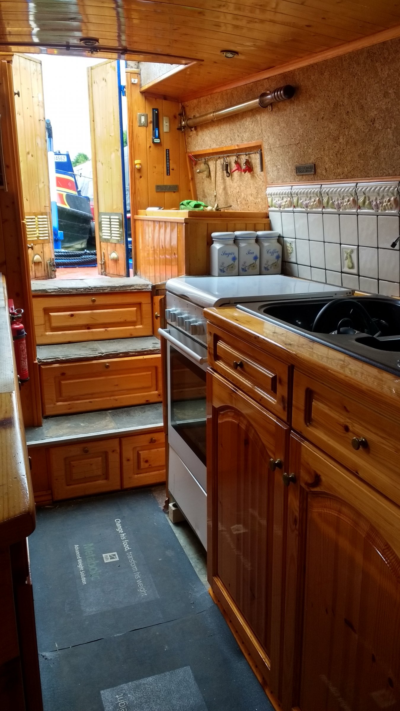
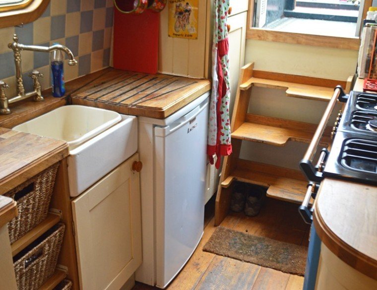
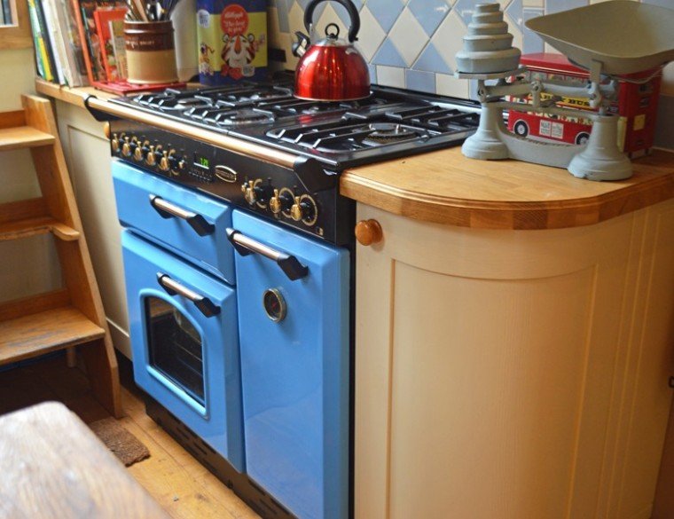
Here is a photo of the boat which started my whole line of thinking about having the galley located where the back cabin is normally situated. However, as you can see, a cooker is about 3' high, so this illustrates the lack of headroom! Interesting to note where they have managed to locate the cooker, in spite of the swim. Shame I couldn't find this when I placed the OP. The second two pictures show another boat with a rear galley, but I think this may have been a semi-trad or cruiser stern - hence no problem with the prop shaft and more headroom.

-
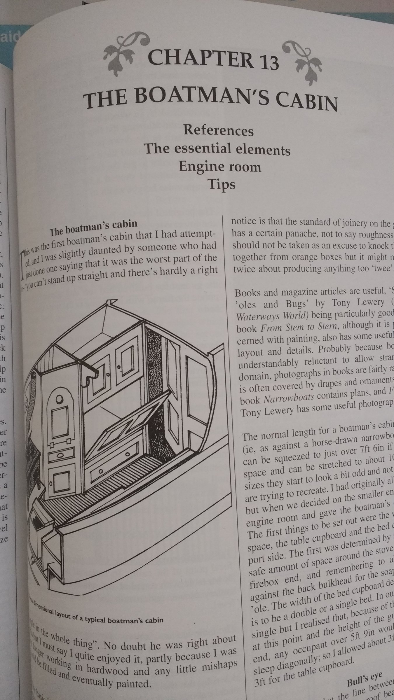
Although not just an invention of boat estate agents... Chapter heading from Graham Booth's Narrow Boat Builders Book!
-
Maybe they named it after Boatman's Cabin?
-
You're kidding? You mean there is actually an engine called a BMC? As well as Lister and Gardner and Russell Newbery?
-
MP, that looks really interesting. I'd love to see any additional photos you may have. My original idea was to have the double bed right up the pointy end, but this also works. It also overcomes the strict limit of length with a cross-bed. Gawd, my drawing is going to have so many rubbings-out, I'll have worn through the paper, lol! Good job I'm not cutting timber yet.
-
Ah yes, a remnant of living in Eire for a while. Doesn't that sound so much nicer than 'airing cupboard'? Also, it has less syllables, so it's easier to say, lol. (The term 'press' originates from the C17th, meaning a cabinet or cupboard, usually for linen.) It seems that the critical thing here, is to ensure I install the engine far enough forward in the boat. It's the one thing which really can't be moved! I can always make use of a little more room in the back cabin, but if it's too tight, it's going to cause big issues. :D:D:D:D I had started to think that rotary action of the crankshaft could be applied to drive a power windlass. How helpful would that be at Hatton?
-
More good points... but I really want to install a 120L vertical calorifier in the engine room, which has got to go on the non-walkway side. I was thinking that 160Kg of batteries would balance that out if they were placed on the opposite side. I'm trying to achieve a reasonably even weight distribution down the boat, to avoid the usual ballasting 'issues'! Will have a play around with the layout. I may set the engine a little further forward and build in a hot press at the end of the side bed. Given that the doorway from the back cabin needs to be central, what is a sensible distance to allow between that bulkhead and the engine, do you think?
-
There is another small side benefit to this approach. By having to have a raised floor in the BMC, I would continue this level through the engine room, which I think should provide room to fit the battery bank under the walkway floor. This would help resolve an issue I currently have with weight distribution. Thanks for the input everyone.
-
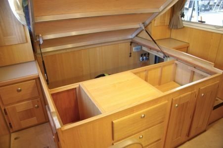
My main reason for adopting a reverse layout was to have a lengthwise 4' 6" double bed, permanently made up. I just find that after a hard days boating, it's nice not to also have to build your bed! A permanent bed also gives the opportunity to have a decent quality domestic mattress and to use an ottoman mechanism to raise the base to expose under-bed storage, as per photo. The hull will be Birmingham Square, which will gain that bit of extra width at floor level to allow passage past the bed. A BMC bed really requires a sectional mattress, not so comfortable IMO and effectively blocks the route through the boat when made up. It also means that the person sleeping nearest the stern would struggle with night-time visits to the loo. That might need another small design feature adding. However... I take your point. I have previously refitted an extended back cabin in a butty and agree it is possible to make use of every cubic inch. If I adopted the BMC as the main sleeping area, it would free up more 'square space' (as opposed to space constrained by swims, tumblehome, etc) further down the boat. I will re-visit my drawings and look seriously at changing it all round. At the moment, it's only lines on paper, so easily altered!
-
OK, right, I see exactly what you mean. This looks like it would be a very elegant and relatively simple system. I will research the dimensions relating to: the engine bearers to bottom of the sump; the relative height of the gearbox output shaft. This will tell me how low the main prop shaft can go. You referred to 'couple of steps which raise the floor up to the rear door at the back of the cabin' - these are needed anyway as a matter of course, so no disadvantage there. My only concern is running UJ's constantly at a fairly acute angle. I think I read somewhere that the maximum is about 20 degrees. I'm wondering if I could take part of your idea - to arrange a low propshaft as you suggest, but then have a single belt drive from the low propshaft to the higher one. I appreciate your suggestion and will follow up these ideas. The thing is, it's terribly easy to over-think, over-engineer and over-complicate things like this, which inevitably means more things to go wrong. I assume that the boat you mentioned must have had a thrust bearing on the shaft supporting the propeller, in order to resist the forward/backward force of the prop? Cheers
-
Wow, that's a novel bit of thinking! I'm not entirely clear if you are suggesting this as a serious option though! All of the obvious 'danger' issues aside, if properly counter-balanced, it would probably work. Curious to know what a BSS examiner would make of it! I'm convinced there has to be a way of overcoming this problem. Do they make flexible shafts heavy enough to transmit 20-30HP?
-
Thank you for your input guys. As I'm at the design stage, I do have control over the shape of the swim, (my preference is for an S-shape) but can indeed gauge whether the gain in useful floor space is worth the hassle. I have seen another boat recently, where they had managed to locate the galley where the BMC would have been, but they had not tackled the prop shaft problem. Consequently, anyone over about 5' 2" would have to stoop. But it was enough to highlight the value of the approach, as - purely in my view, a BMC is a waste of space as I really wouldn't use it. Plus the kettle would be in easy reach of the helm! The design would allow the galley and engine room to be fitted into the rearmost 18' of the cabin, allowing the remaining 28' to be allocated to saloon, cabin and bathroom, whilst still retaining a 'proper' 10' bow. So I feel it's worth trying to crack this. I've sent an enquiry to ARS Anglian Diesels to get an idea of costs for a hydraulic solution, so am not eliminating anything at the moment. My gut feeling is that the belt drive option would be quiet and elegant, but have a nagging doubt that I'm over-simplifying it!